The DVB satellite, cable and
SMATV systems
Why the technical choices were made
J. Seseña (Hispasat)1. Introduction
The digital broadcasting systems that have been defined by the Digital Video Broadcasting (DVB) Project represent a family of baseline specifica-tions which match the characteristics of the deliv-ery medium for which each system has been pro-duced. Certain trade-offs have been made in order to develop the optimum solution, not only from the technical point of view but also from the commer-cial viewpoint. This is considered by the broad-casting community as one of the key successes of the DVB Project: the technical solutions are driven by market requirements. Thus, the various DVB systems satisfy the technical, operational and com-mercial requirements of the particular transmis-sion network (satellite, cable, terrestrial) for which they have been designed, while keeping a high level of commonality between them; any “peculia-rities” are restricted to those aspects of the system which are network-dependent.
The author describes the DVB systems that have been defined for the digital distribution of television, sound and data services via satellite, cable and SMATV networks.
Reasons are given for why the technical choices were made and the author briefly discusses future trends in digital broadcasting, especially the move towards interactive broadcasting.
A complete family of specifications has been pro-duced by the DVB consortium. Each DVB system is, at the same time, flexible enough to satisfy specific requirements for the implementation of a specific service.
Now that the DVB broadcasting systems have been defined, a further step towards interactive services is being undertaken, thus enabling the cur-rent capabilities of the DVB systems to be up-graded.
Original language: English Manuscript received 26/10/95.
2. European DVB requirements
The DVB family of systems has been produced according to a set of commercial requirements, which have then been used to check the technical specifications in order to define the practical sys-tems for users and manufacturers.
Among the most relevant issues taken into account when developing the DVB baseline specifications are the following:
– the source coding, framing and multiplexing should use only MPEG-2;
– there should be maximum commonality within each medium and between media;
– the target retail prices for direct-to-home (DTH) consumer equipment should be less than 600 ECUs at the introduction phase (1995) and less than 350 ECUs within 2 years of introduc-tion;
– the target price for head-end equipment in Satellite Master-Antenna Television (SMATV) applications should not exceed 2500 ECUs at the introduction phase and less than 1500 ECUs within 2 years of introduction;
– the transmission system should accommodate the 4:3, 16:9 and 2.21:1 picture formats; – the audio source coding should be MPEG layer II
(MUSICAM);
– the Integrated Receiver Decoder (IRD) should provide facilities for “fast channel hopping” and the service acquisition time for all services should be less than 0.5 seconds;
It should be noted that, following the definition of the DVB baseline specifications and the adoption of them by ETSI1, the first commercial services
started in 1995. Furthermore, extensive tests have been carried out within the Euro-Image Project2 in order to assess how well DVB-specified equip-ment (transmitters and receivers) works in
prac-1. European Telecommunication Standards Institute. 2. The Euro-Image Project was set up to study the
perfor-mance of DVB systems for satellite and cable delivery, and the Service Information aspects. Coordinated by the EBU, it was partially funded by the European Com-mission.
tice. Those tests have confirmed the performance expected of DVB-specified equipment, thereby supporting the technical choices that were made when defining the architecture and normative re-quirements (ETSI standards) of the DVB systems [1], [2], [3].
3. DVB broadcasting systems The overall architecture of the DVB systems is shown in Fig. 1.
The function of each block is as follows:
1) Source coding and multiplexing
This block provides the tools to compress the digital vision and sound signals to the rate required by the data stream which, in turn, de-pends on the specified quality of the television signal. This process allows a reduction of the bandwidth needed.
DVB has adopted MPEG-2 [4] as the tool-box from which to make up systems which incorpo-rate greater or lesser degrees of sophistication. The DVB recommendations on how to imple-ment MPEG-2 are described in [5] and general background information is provided in [6]. From a commercial viewpoint, MPEG-2 was identified as the best candidate because of its capacity to provide maximum commonality among different transmission media – particu-larly satellite, cable, SMATV and terrestrial – and its capacity to permit flexible Service Information (SI) for all configurations of ser-vices and service components, including tele-ision, sound and data.
The MPEG-2 multiplex system was chosen by the DVB Technical Module (DVB-TM) which took into account, among other things, the following features:
– its packet structure, which provides efficient system synchronization and enables the assembly of all the components in a single bit stream;
– it is suitable for recording purposes at the receiver since the bit stream includes its own presentation mechanism;
– it is the system which best covers the require-ments of the different transmission media (satellite, cable, terrestrial, etc.).
Source coding and multiplexing
Channel adaptation (coding and modulation)
Transmission media
Demodulation
and decoding Presentation
Figure 1 Overall architecture of the DVB system.
2) Channel adaptation
This block helps to facilitate the transmission of the MPEG-2 Transport Stream (MPEG-TS) over the specific delivery medium. It is neces-sary to adopt particular modulation and coding schemes to ensure that the signal is matched to the channel environment. Depending on the channel characteristics, either a more robust or a more spectrum-efficient modulation scheme may be optimum.
3) Transmission media
The transmission media can be based on deliv-ery by satellite, cable, SMATV or terrestrial transmitters (UHF or microwave). Each one has its own physical properties which have been considered in the development of the DVB sys-tems. Obviously, the DVB Project does not specify particular requirements for the trans-mission medium, but the transtrans-mission channel characteristics have duly been taken into ac-count to ensure that reception of the MPEG-TS is virtually free of errors. The concept utilized by DVB is based on quasi-error-free3 (QEF) reception of the MPEG-TS signal.
4) Demodulation and decoding
These functions are implemented in the receiv-ing chain in order to acquire the baseband signal (i.e. the MPEG-TS) and to remove the RF signal carrier. It is important that the receiver takes into account any variations in the channel re-sponses (amplitude and group delay) with time and under particular conditions.
Digital signals are sensitive to echoes present in the channel. To cope with this, equalization techniques are available when needed to com-pensate in an adaptive way for the most relevant channel distortions.
3. QEF reception means that less than one uncorrected error-event-per-hour should be presented to the MPEG decoder.
5) Presentation
The display formats (i.e. aspect ratios) required by DVB are 4:3, 16:9 and 2.21:1. These formats should preferably be transmitted with the full number of active lines. To enable a transmitted format to be displayed on a television set that is designed to receive a different display format, the DVB system transmits dynamic “pan” vectors.
4. The DVB-S system for satellite broadcasting As the source video and sound coding are based upon the MPEG-2 Transport Stream, the DVB family of systems places specific emphasis on the optimization of the channel coding and modula-tion schemes.
The DVB satellite system (DVB-S) has been de-fined for the broadcasting and distribution of digi-tal multiprogramme television and HDTV ser-vices in the Broadcast Satellite Service (BSS) and the Fixed Satellite Service (FSS) bands4. The DVB-S system is also intended to provide Direct-To-Home (DTH) services for consumer Integrated Receiver Decoders (IRDs), as well as Satellite Master-Antenna Television (SMATV) systems and cable (CATV) systems where the DVB signals need to be remodulated for distribution purposes. The DVB-S system is suitable for use on satellites whose transponder bandwidth lies within the range 26 MHz to 54 MHz. Current European satellites which can carry the DVB-S signals include Astra, DFS, Eutelsat, Hispasat, TDF, Telecom, Tele-X and Thor.
By using a time-division-multiplex (TDM), a variety of digital vision, sound and data services can be superimposed onto a single RF carrier in the transponder. The number of different services which can be multiplexed onto the carrier is a func-tion of the television picture quality required and the marketing strategy of each broadcaster.
4. FSS downlink band = 10.7 – 11.7 GHz 12.5 – 12.75 GHz BSS downlink band = 11.7 – 12.5 GHz. Baseband physical interface and sync Sync inversion and energy dispersal Outer coder Convolutional interleaver I = 12 bytes Inner coder Baseband shaping QPSK modulator Data Puncturing & mapping IF physical interface Clock Figure 2 DVB satellite transmission system.
1 2 3 4 5 6 7 8 9 10 11 12 13 14 15 1 0 0 1 0 1 0 1 0 0 0 0 0 0 0 Enable Clear/randomized data input Randomized/de-randomized data output AND ex-OR 00000011 ... ex-OR
In the case of TDM, the satellite can be operated at saturation since there is only one carrier in the transponder. However, an alternative multi-carrier system called frequency-division multiple access (FDMA) can be used for satellite delivery. In this case, it is necessary to operate the satellite trans-ponder with an output back-off (OBO) in order to limit the level of the intermodulation products. The total power available from a given transpond-er to each carritranspond-er, taking into account the required OBO, is lower than in the TDM case. Consequent-ly, the bit energy (Eb) value for each carrier and the
link budget margin are reduced. Furthermore, tak-ing into account the bandwidth resources in the transponder, the total capacity is lower in the case of FDMA because of the need to keep guard-bands between the carriers.
One advantage of FDMA technology is that it allows the possibility to uplink signals to the same transponder from different sites, thus avoiding the need to transport all the TV programmes to one par-ticular site. It is interesting to note that the European Space Agency is in charge of a new project called SKYPLEX which aims to find ways of compensat-ing for the OBO required when uscompensat-ing the FDMA system. This project will develop ground-based equipment and some intelligent on-board proces-sing in the satellite to create a multiplex capability at the spacecraft; the downlink will be a TDM single-carrier system with the satellite transponder operating at saturation point, while the uplink will be a multi-site mixture of several carriers.
4.1. DVB-S transmission chain A schematic diagram of a DVB-S transmission system is shown in Fig. 2. The source signals have to be adapted to the characteristics of the satellite channel and, therefore, they are processed in the following ways:
1) Transport multiplex adaptation and randomization for energy dispersal
The input bit stream has to be organized in fixed-length packets (188 bytes) according to the MPEG-2 Transport Stream. One of these bytes is a synchronization word; there are also three header bytes in the stream and the remain-ing bytes contain the information data. In order to ensure adequate binary transitions, a randomization process has to be applied to the data (see Fig. 3) The shift register is initiated by the sequence at the start of every eight transport packets. In order to ensure the initialization sequence for the descrambling process, the MPEG-2 sync byte of the first packet is bit-wise inverted.
The randomization process has to be active to avoid the emission of an unmodulated carrier. The spectrum spreading which results from the use of the scrambling process is shown in Fig. 4.
2) Outer coding
This is applied in order to produce an error-protected packet. A shortened Reed-Solomon (RS) code is applied (type 204,188) with the ability to correct eight random byte errors.
3) Convolutional interleaving
This is based on the Fourney convolutional approach with I = 12. Although more compli-cated to produce, the convolutional type of interleaver requires about half the chip imple-mentation area (and hence, half the memory) required by a block interleaver, without any reduction in performance.
4) Inner coding (convolutional)
This function allows the use of a flexible code rate in order to choose the most convenient level
Figure 3 Randomization process.
of error correction for each service or bit-rate. It is based on the well-known puncturing tech-nique, usually included in commercially-avail-able Viterbi decoders. The code rates can be 1/2, 2/3, 3/4, 5/6 and 7/8. This flexibility allows the user bit-rate to be optimized according to the available satellite EIRP, receiving antenna size and service availability targets.
After detailed trade-offs between complexity and performance, the DVB Project has adopted a constraint length of K = 7, which corresponds to 64 states. Compared with another option studied (K = 6) and for a fixed puncturing rate, the coding gain with a constraint length of K = 7 is higher, although it was noted that the con-volutional code with a constraint length of K = 6 is less complex.
The received signal is also corrupted by additive white Gaussian noise (AWGN). Thus, a power-ful error-correcting scheme is needed to achieve a QEF link with low carrier-to-noise (C/N) ratios. This is achieved by means of an inner convolutional code, concatenated with an outer Reed-Solomon code. A “soft decision” Viterbi decoder is used to decode the inner code. Be-cause of its intrinsic behaviour, error bursts appear at the output of the Viterbi decoder. These are broken up by using a symbol de-interleaver which splits them into isolated or small manageable bursts of erroneous bytes which can be corrected by the outer Reed-Solomon decoder.
The performance and complexity of this system are mainly influenced by three parameters:
– the number of states of the convolutional code;
– the rate of the convolutional code;
– the error-correcting capability of the Reed-Solomon code.
Although the system is complicated, it has the ability to correct errors in an optimum way; by sharing the task between the RS decoder and the Viterbi decoder, the overall system complexity is minimized.
5) Baseband shaping of the signal pulse
A transmission roll-off factor of 35 % has been selected, following extensive studies and com-puter simulation analysis.
6) Modulation
With the aim of allowing the receiver to detect the signal adequately at very low C/N ratios, a relatively-simple channel modulation scheme has been adopted: quaternary phase shift keying (QPSK). This scheme has a constant envelope amplitude and widely-separated phase states, which give a high degree of ruggedness against channel noise and interference. QPSK allows the satellite travelling-wave tube amplifier (TWTA) to operate at saturation and the losses are less than 1 dB. Also, QPSK is a very mature solution which is widely used in professional applications, and is also suitable for the con-sumer market because of its ruggedness when subjected to synchronization inaccuracy. The encoded digital symbols are processed by a con-ventional Gray-coded QPSK modulator, which provides absolute mapping at the desired frequency. –100 –80 –60 –40 –20 0 20 40 60 80 100 –60 –70 –50 –40 –30 –20 –10 MHz dB Frequency offset Power density
Power spectrum at the modulator output
Figure 4
Effects of scrambling on the spectrum shaping.
Baseband physical interface Energy dispersal removal and sync inversion Outer decoder Convolutional de-interleaver I = 12 bytes Inner decoder (Viterbi) Matched filter QPSK demodulator Data Depuncturing IF physical interface Clock Sync decoder Carrier and clock recovery
Clock & sync generator code rate control I
Q
4.2. DVB-S receiving chain
The receiving chain uses similar functional blocks to those used in the transmitting chain. The main receiving functions are as follows (see Fig. 5):
1) IF interface and QPSK demodulator
This unit performs the quadrature-coherent demodulation function, the analogue-to-digital conversion and provides soft-decision I and Q information to the inner decoder.
2) Matched filter
This unit performs complementary pulse-shape filtering, of the raised cosine type, according to the roll-off of 35% in the transmitting chain. A finite impulse response (FIR) digital filter can be used to provide equalization of the linear channel distortions in the IRD.
3) Carrier/clock recovery unit
This device recovers the demodulator nization. The probability of loss of synchro-nization over the full C/N range of the demodu-lator should be very low.
4) Inner decoder
This unit performs first-level error-protection decoding. It should operate at an input-equivalent “hard decision” bit-error-rate (BER) in the order of 10-1 to 10-2 (depending on the
adopted code rate), and should produce an out-put BER of about 2.10-4 or lower. This output BER corresponds to a QEF service after outer code correction. This unit can also make use of “soft decision” information; it evaluates each of
the code rates and puncturing configurations until “lock” is acquired. Furthermore, it can re-solve /2 demodulation phase ambiguities.
5) Sync byte decoder
This decoder provides synchronization infor-mation for the de-interleaving process. It can also resolve any ambiguities arriving from the QPSK demodulator (which were not detected by the Viterbi decoder).
6) Convolutional de-interleaver
This component allows the error bursts arriving from the inner decoder to be randomized on a byte basis, in order to improve the burst-error-correction capability of the outer decoder.
7) Outer decoder
This unit provides second-level error protec-tion. It can provide QEF output (i.e. with a BER of about 10-10 to 10-11) in the presence of input error bursts at a BER of about 7.10-4 or better
with infinite byte interleaving. In the case of an interleaving depth of I = 12, a BER of 2.10-4 is
assumed for QEF decoding.
8) Energy dispersal removal
This component recovers the user bit-rate by removing the randomizing pattern used for energy dispersal purposes, and changes the in-verted sync byte to its normal MPEG-2 value.
9) Base-band physical interface
This component adapts the data structure to the format and the protocol required by the external interface.
Figure 5 Conceptual block diagram of the DVB satellite receiver.
ÁÁÁÁÁ ÁÁÁÁÁ ÁÁÁÁÁ Transponder bandwidth (MHz) ÁÁÁÁÁÁ ÁÁÁÁÁÁ ÁÁÁÁÁÁ Typical symbol rate (Mbaud) ÁÁÁÁÁÁÁÁÁÁÁÁÁÁÁÁÁÁ ÁÁÁÁÁÁÁÁÁÁÁÁÁÁÁÁÁÁ ÁÁÁÁÁÁÁÁÁÁÁÁÁÁÁÁÁÁ Useful bit-rate capacity (Mbit/s) ÁÁÁ ÁÁÁ ÁÁÁ –3 dB ÁÁÁ ÁÁÁ ÁÁÁ –1 dB ÁÁÁÁÁÁ ÁÁÁÁÁÁ ÁÁÁÁÁÁ ÁÁÁÁ ÁÁÁÁ ÁÁÁÁ Code rate 1/2 ÁÁÁÁÁ ÁÁÁÁÁ ÁÁÁÁÁ Code rate 2/3 ÁÁÁÁ ÁÁÁÁ ÁÁÁÁ Code rate 3/4 ÁÁÁÁÁ ÁÁÁÁÁ ÁÁÁÁÁ Code rate 5/6 ÁÁÁÁ ÁÁÁÁ ÁÁÁÁ Code rate 7/8 ÁÁÁ ÁÁÁ 54 ÁÁÁ ÁÁÁ 48.6ÁÁÁÁÁÁ ÁÁÁÁÁÁ 42.2 ÁÁÁÁ ÁÁÁÁ 38.9 ÁÁÁÁÁ ÁÁÁÁÁ 51.8 ÁÁÁÁ ÁÁÁÁ 58.3 ÁÁÁÁÁ ÁÁÁÁÁ 64.8 ÁÁÁÁ ÁÁÁÁ 68.0 ÁÁÁ ÁÁÁ 46 ÁÁÁ ÁÁÁ 41.4ÁÁÁÁÁÁ ÁÁÁÁÁÁ 35.9 ÁÁÁÁ ÁÁÁÁ 33.1 ÁÁÁÁÁ ÁÁÁÁÁ 44.2 ÁÁÁÁ ÁÁÁÁ 49.7 ÁÁÁÁÁ ÁÁÁÁÁ 55.2 ÁÁÁÁ ÁÁÁÁ 58.0 ÁÁÁ ÁÁÁ 40 ÁÁÁ ÁÁÁ 36.0ÁÁÁÁÁÁ ÁÁÁÁÁÁ 31.3 ÁÁÁÁ ÁÁÁÁ 28.8 ÁÁÁÁÁ ÁÁÁÁÁ 38.4 ÁÁÁÁ ÁÁÁÁ 43.2 ÁÁÁÁÁ ÁÁÁÁÁ 48.0 ÁÁÁÁ ÁÁÁÁ 50.4 ÁÁÁ ÁÁÁ 36 ÁÁÁ ÁÁÁ 32.4ÁÁÁÁÁÁ ÁÁÁÁÁÁ 28.1 ÁÁÁÁ ÁÁÁÁ 25.9 ÁÁÁÁÁ ÁÁÁÁÁ 34.6 ÁÁÁÁ ÁÁÁÁ 38.9 ÁÁÁÁÁ ÁÁÁÁÁ 43.2 ÁÁÁÁ ÁÁÁÁ 45.4 ÁÁÁ ÁÁÁ 33 ÁÁÁ ÁÁÁ 29.7ÁÁÁÁÁÁ ÁÁÁÁÁÁ 25.8 ÁÁÁÁ ÁÁÁÁ 23.8 ÁÁÁÁÁ ÁÁÁÁÁ 31.7 ÁÁÁÁ ÁÁÁÁ 35.6 ÁÁÁÁÁ ÁÁÁÁÁ 39,6 ÁÁÁÁ ÁÁÁÁ 41.6 ÁÁÁ ÁÁÁ 30 ÁÁÁ ÁÁÁ 27.0 ÁÁÁÁÁÁ ÁÁÁÁÁÁ 23.4 ÁÁÁÁ ÁÁÁÁ 21.6 ÁÁÁÁÁ ÁÁÁÁÁ 28.8 ÁÁÁÁ ÁÁÁÁ 32.4 ÁÁÁÁÁ ÁÁÁÁÁ 36.0 ÁÁÁÁ ÁÁÁÁ 37.8 ÁÁÁ ÁÁÁ 27 ÁÁÁ ÁÁÁ 24.3 ÁÁÁÁÁÁ ÁÁÁÁÁÁ 21.1 ÁÁÁÁ ÁÁÁÁ 19.4 ÁÁÁÁÁ ÁÁÁÁÁ 25.9 ÁÁÁÁ ÁÁÁÁ 29.2 ÁÁÁÁÁ ÁÁÁÁÁ 32.4 ÁÁÁÁ ÁÁÁÁ 34.0 ÁÁÁ ÁÁÁ 26 ÁÁÁ ÁÁÁ 23.4 ÁÁÁÁÁÁ ÁÁÁÁÁÁ 20.3 ÁÁÁÁ ÁÁÁÁ 18.7 ÁÁÁÁÁ ÁÁÁÁÁ 25.0 ÁÁÁÁ ÁÁÁÁ 28.1 ÁÁÁÁÁ ÁÁÁÁÁ 31.2 ÁÁÁÁ ÁÁÁÁ 32.8 4.3. Exploitation of the transponder bandwidth
The most important feature of the DVB-S system is its flexibility to accommodate a wide range of possibilities: useful bit-rate, forward error correc-tion (FEC), transponder bandwidth, etc. Table 1 gives examples of the useful bit-rate capacity (Ru) achievable on a satellite transponder with a band-width (BW) corresponding to a BW/Rs = 1.28, where Rs is the transmission symbol rate. Other BW/Rs values may be adopted for different service requirements, depending on the trade-off implemented between the transmission capacity and the bit-energy-to-noise-density ratio (Eb/No).
Flexibility is one of the remarkable achievements of the DVB-S system (also applicable to the DVB-C and DVB-SMATV systems). No specific bit-rates or FEC code rates have been established and the concept of variable-symbol-rate receivers – with the ability to identify the transmitted FEC rate – constitutes the real advantage of DVB to serve the market needs.
4.4. Antenna size
During the process of developing the DVB-S system, attention was paid to the antenna size re-quired to receive the transmissions in simple DTH applications. To compute the required antenna size, it is necessary to know the Eb/No that is
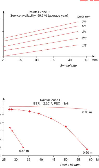
need-ed by the demodulator to ensure a BER of better than 2.10-4 (QEF conditions) after Viterbi decod-ing. The C/N can then be derived and finally, the required antenna gain (and hence its size). Figs. 6 and 7 illustrate some examples of the rela-tionships between these parameters. For example,
with reference to Fig. 6, for a bit-rate of 29 Mbauds and a code rate of 2/3, the required antenna size is about 60 cm, assuming a service availability of 99.7% (average year) in rainfall zone K.
Note the impact that a symbol rate increase has on the required antenna size. It is thus convenient to make a trade-off between the required antenna size and the symbol rate for each service.
Fig. 7 shows the relationship between service availability and useful bit-rate, as a function of the antenna size. For a useful bit-rate of 38.9 Mbit/s with an FEC code rate of 3/4 (corresponding to a symbol rate of 28.1 Mbauds) and an antenna size of 60 cm, a service availability (average year) of 99.9% is reached. Note again the relationship be-tween the bit-rate and the antenna size. In this case, the bit-rate has been expressed in terms of useful bit-rate.
The Euro-Image Project has made a detailed anal-ysis of the performance of the DVB-S system, by using it in real scenarios. Those results are re-ported in [7]. Among others, the following effects have been evaluated by means of software and hardware simulations, IF loops and real satellite transmissions. The results obtained confirm the suitability of the DVB-S system to work in real conditions with excellent performance.
1) Bandwidth limitation
This is the degradation due to the limited band-width of the transponder input multiplexer (IMUX) and output multiplexer (OMUX) fil-ters, mainly the OMUX filter. It depends on the BW/Rs ratio and is around 0.4 dB for reason-able BW/Rs ratios.
Table 1
Examples of useful bit-rate capacity.
2) Non linearities
Non-linearities in the transponder TWTA can cause intersymbol interference (ISI). The level of this interference depends on the TWTA oper-ating point and is a maximum at saturation point. Typically, the degradation due to ISI lies in the range 0 to 0.7 dB.
3) Power reduction due to non linearities
This effect, which is different from intersymbol interference, is due to the appearance of second-ary side lobes of the signal spectrum, caused by the non-linear behaviour of the TWTA and the filtering that the signal suffers at the OMUX. The power reduction due to this effect has been evaluated by computer simulations; it is around 0.9 dB when the TWTA is operating at satura-tion point.
4) Modem implementation margin
This is the difference between the theoret-ical performance and the real performance of modems working back-to-back. A value of 0.8 dB (as used in the DVB-S specification) has been taken as a reference. Real tests have confirmed this value for most of the cases.
5) Noise bandwidth increase due to the outer code
The outer code causes the noise bandwidth of the signal, after decoding, to increase by a factor of 10 log 204/188 (i.e. around 0.36 dB). This increase should be taken into account when using the Eb/No that refers to the useful
bit-rate before RS encoding has taken place. The reference values to adopt when planning DVB-S services are detailed in Table 2 (on the next page). They represent the most accurate assump-tions for the performance of DVB-S equipment and have been obtained from the work carried out in the Euro-Image Project, coordinated by the EBU.
This table includes figures that can be assumed in the planning of DVB-S services to ensure their compatibility in terms of protection ratios (PR). It can be seen that, for a full digital scenario, a significant relaxation of the criteria is possible when compared with the current full analogue scenario. Values of about 16 dB for co-channel PR and 12 dB for adjacent channel PR are rec-ommended. In the case of the hybrid digital/ analogue scenario, the conclusions show that a value of about 23 dB for co-channel PR and
15 dB for adjacent-channel PR (half channel bandwidth overlapping) could be appropriate when a digital signal interferes with the analogue TV/FM signals. On the other hand, when an analogue signal interferes with a digital DVB-S signal, the recommended protection ratios de-crease to 17 dB for co-channel PR and 13 dB for adjacent-channel PR.
In conclusion, the introduction of the DVB-S system will guarantee a better exploitation of the limited orbit-spectrum resources that are available for satellite broadcasting.
However, representations should be made to the appropriate regulatory and frequency planning bodies, to ensure that the assignments for digital broadcasting satellite services are consistent with the results obtained.
20 25 30 35 40 45 0.4 0.6 0.8 1.0 Symbol rate Mbaud m Antenna diameter Code rate 1/2 2/3 3/4 5/6 7/8 Rainfall Zone K
Service availability: 99.7 % (average year)
50 25 30 35 40 45 99.5 Useful bit-rate Mbit/s % Rainfall Zone E BER = 2.10–4, FEC = 3/4 99.6 99.7 99.8 99.9 100 A vailability 55 60 99.4 0.45 m 0.60 m 0.90 m Figure 6 (upper) Examples of antenna diameter versus symbol rate.
Figure 7 (lower) Examples of availability versus useful bit-rate.
ÁÁÁÁÁÁÁÁÁÁ ÁÁÁÁÁÁÁÁÁÁ ÁÁÁÁÁÁÁÁÁÁ ÁÁÁÁÁÁÁÁÁÁ Parameter ÁÁÁÁÁ ÁÁÁÁÁ ÁÁÁÁÁ ÁÁÁÁÁ Euro Image reference values (dB) ÁÁÁÁÁÁÁÁÁÁ ÁÁÁÁÁÁÁÁÁÁ
Bandwidth limitation degradation ÁÁÁÁÁ
ÁÁÁÁÁ 0.1 – 0.4 ÁÁÁÁÁÁÁÁÁÁ
ÁÁÁÁÁÁÁÁÁÁ
Non linearities (ISI) degradation ÁÁÁÁÁ
ÁÁÁÁÁ 0.0 – 0.7 ÁÁÁÁÁÁÁÁÁÁ
ÁÁÁÁÁÁÁÁÁÁ
ÁÁÁÁÁÁÁÁÁÁ
Noise bandwidth increase 10log(204/188) ÁÁÁÁÁ ÁÁÁÁÁ ÁÁÁÁÁ 0.36 ÁÁÁÁÁÁÁÁÁÁ ÁÁÁÁÁÁÁÁÁÁ
Interference losses (intrasystem)
ÁÁÁÁÁ
ÁÁÁÁÁ 0.0 – 0.3
ÁÁÁÁÁÁÁÁÁÁ
ÁÁÁÁÁÁÁÁÁÁ
Power reduction due to non linearities ÁÁÁÁÁ ÁÁÁÁÁ 0.9 ÁÁÁÁÁÁÁÁÁÁ ÁÁÁÁÁÁÁÁÁÁ
Modem implementation margin
ÁÁÁÁÁ ÁÁÁÁÁ 0.8 ÁÁÁÁÁÁÁÁÁÁ ÁÁÁÁÁÁÁÁÁÁ ÁÁÁÁÁÁÁÁÁÁ ÁÁÁÁÁÁÁÁÁÁ ÁÁÁÁÁÁÁÁÁÁ
Distortion due to SMATV distribution network SMATV-S SMATV-S equalized SMATV-IF ÁÁÁÁÁ ÁÁÁÁÁ ÁÁÁÁÁ ÁÁÁÁÁ ÁÁÁÁÁ 1.00 – 1.85 0.25 – 0.50 3 ÁÁÁÁÁÁÁÁÁÁ ÁÁÁÁÁÁÁÁÁÁ ÁÁÁÁÁÁÁÁÁÁ ÁÁÁÁÁÁÁÁÁÁ ÁÁÁÁÁÁÁÁÁÁ ÁÁÁÁÁÁÁÁÁÁ ÁÁÁÁÁÁÁÁÁÁ
Required Eb/No AWGN (note 1) FEC 1/2 FEC 2/3 FEC 3/4 FEC 5/6 FEC 7/8 ÁÁÁÁÁ ÁÁÁÁÁ ÁÁÁÁÁ ÁÁÁÁÁ ÁÁÁÁÁ ÁÁÁÁÁ ÁÁÁÁÁ 4.6 5.1 5.6 6.3 6.8 ÁÁÁÁÁÁÁÁÁÁ ÁÁÁÁÁÁÁÁÁÁ ÁÁÁÁÁÁÁÁÁÁ ÁÁÁÁÁÁÁÁÁÁ ÁÁÁÁÁÁÁÁÁÁ ÁÁÁÁÁÁÁÁÁÁ
Required Eb/No satellite (note 2) FEC 1/2 FEC 2/3 FEC 3/4 FEC 5/6 FEC 7/8 ÁÁÁÁÁ ÁÁÁÁÁ ÁÁÁÁÁ ÁÁÁÁÁ ÁÁÁÁÁ ÁÁÁÁÁ 5.5 6.0 6.6 7.2 7.9 ÁÁÁÁÁÁÁÁÁÁ ÁÁÁÁÁÁÁÁÁÁ ÁÁÁÁÁÁÁÁÁÁ ÁÁÁÁÁÁÁÁÁÁ ÁÁÁÁÁÁÁÁÁÁ Protection Ratios:
Full Digital Scenario (BW/Rs = 1.28) CCI H-ACI (note 3) ÁÁÁÁÁ ÁÁÁÁÁ ÁÁÁÁÁ ÁÁÁÁÁ ÁÁÁÁÁ 16 12 ÁÁÁÁÁÁÁÁÁÁ ÁÁÁÁÁÁÁÁÁÁ ÁÁÁÁÁÁÁÁÁÁ ÁÁÁÁÁÁÁÁÁÁ ÁÁÁÁÁÁÁÁÁÁ Hybrid Digital/Analogue Scenario
CCI, D-to-A CCI, A-to-D H-ACI, D-to-A H-ACI, A-to-D ÁÁÁÁÁ ÁÁÁÁÁ ÁÁÁÁÁ ÁÁÁÁÁ ÁÁÁÁÁ 23 17 15 13
Note 1: The values of Eb/No AWGN take into account the contribution from the modem implementa-tion margin (0.8 dB) and the noise bandwidth increase (10 log (204/188)).
Note 2: The required Eb/No satellite values add the following contributions to the required Eb/No AWGN: bandwidth limitation degradation and non linearities (ISI). Power reduction due to non linearities and intrasystem interference losses are not included in the required Eb/No satellite values.
Note 3: H-ACI is adjacent channel interference from a signal which is half a channel width away (F-ACI is the case where the interfering signal is a full channel width away).
5. The DVB-C system for cable distribution
Cable television networks are normally structured like trees, with trunk routes, branches and sub-branches. In order to achieve cost-effective and reliable distribution of the television and sound programmes, coaxial cable and hybrid fibre/ coaxial (HFC) technologies are used.
The DVB cable distribution system (DVB-C) is designed to be fed by a combination of satellite signals, local programme sources, and signals in-coming from contribution links; the appropriate programme content is assembled from those sources at the CATV head-end. The signals arriv-ing from a satellite will usually need to be demulti-plexed at the head-end in order to insert them into the cable programme multiplex.
A block diagram of the DVB-C transmission chain is shown in Fig. 8. The most important character-istics of the DVB-C system are as follows (see also [8]):
1) Commonality with the DVB-S system in terms of coding, multiplexing, framing, interleaving, outer codes and variable symbol rates. This constitutes a noticeable step towards economies of scale and the transparency of signals passing through different networks.
2) The principal challenge in cable environments is the limited channel bandwidth (8/7 MHz). Although a cable channel is typically more complex than a satellite channel (because of the short-delay echoes and the intermodulation products which need to be taken into account), CATV networks represent a suitable medium for digital TV broadcasting.
The DVB-C system has been defined to make optimum use of the limited capacity available on the cable channel. Single-carrier modula-tion, using 16-, 32- and 64-QAM5 has been cho-sen, as it more-closely matches the characteris-tics of the cable channel than the other modulation schemes that were considered. Also, it offers lower sensitivity to interference and a 10% more useful bit-rate than these other schemes. Furthermore, the preference of the industrial manufacturers for QAM was taken into account when making this choice. The QAM systems currently specified for DVB-C can be extended in the future to include a greater number of constellations (e.g. 128-and 256-QAM).
5. Quadrature amplitude modulation.
Table 2
Reference values to adopt when planning DVB-S services.
I Q Matched filter and equalizer Differential decoder Symbol to byte mapping Convolutional de-interleaver Reed-Solomon decoder Sync 1 inversion and energy dispersal remover
Carrier, clock and sync recovery m m 8 8 8 8 Data Clock BB Physical interface Cable IRD I Q Baseband shaping Differential encoder Byte to multiple mapping Convolutional Interleaver I = 12 bytes Reed-Solomon coder (204,188) m m 8 8 8 Data Clock Baseband physical interface Cable head-end Sync 1 inversion and random-ization QAM modulator and RF physical interface RF physical interface and QAM demodulator RF cable channel Baseband interface to:
– local MGEG-2 programme sources – contribution links
– remultiplexers, etc.
Clock and sync generator
3) No convolutional inner code is needed. The rationale for taking this decision was based on the higher C/N ratios that are normally available on cable networks.
4) A roll-off factor of 15% has been specified for DVB-C, which is sharper than for the satellite system. It will allow the transmission bit-rate to be maximized in the cable channel, thus helping to achieve transparent distribution of an in-coming satellite signal along the cable network. 5) At the very early stage of definition, it was thought that training sequences for the adaptive equalizers would be necessary, in order to achieve transient times of less than 50 ms in the cable network, and also to enable an extension of the modulation system to 128- or 256-QAM. However, based on theoretical considerations and practical computer simulations, it was con-cluded that both modulation options could be achieved with an optimized “blind”
equaliza-tion which does not include any training sequences6.
If training sequences should become a necessity for applications not foreseeable at this time, they could be incorporated in the MPEG-2 transport stream as private data streams which would re-quire between 0.5 and 2% of the available capacity. In common with the other transport packets, care would need to be taken that these training sequence packets – in passing along the whole encoding chain (energy dispersal, RS coder, convolutional interleaver, etc.) – do not lose their training capa-bilities.
Table 3, which is taken from [9], shows the region of possible transmissions rates, the associated symbol rates and the occupied bandwidth for QAM with 16-, 32- and 64-state constellations.
6. A “training sequence” is a signal of fixed shape. The receiver adjusts its equalization until the shape is correct.
Figure 8 Conceptual diagram of the main elements at the cable head-end and at the receiving site.
ÁÁÁÁ ÁÁÁÁ ÁÁÁÁ ÁÁÁÁ Trans-mission rate (Mbit/s) ÁÁÁÁ ÁÁÁÁ ÁÁÁÁ ÁÁÁÁ Symbol rate (Mbaud) ÁÁÁÁ ÁÁÁÁ ÁÁÁÁ ÁÁÁÁ Bandwidth (MHz) ÁÁÁÁÁ ÁÁÁÁÁ ÁÁÁÁÁ ÁÁÁÁÁ Modu-lation ÁÁÁÁ ÁÁÁÁ 18.9 – 25.2ÁÁÁÁ ÁÁÁÁ 5.13 – 6.84ÁÁÁÁ ÁÁÁÁ 5.90 – 7.86ÁÁÁÁÁ ÁÁÁÁÁ 16-QAM ÁÁÁÁ ÁÁÁÁ 26.1 – 31.9ÁÁÁÁ ÁÁÁÁ 5.66 – 6.92ÁÁÁÁ ÁÁÁÁ 6.51 – 7.96ÁÁÁÁÁ ÁÁÁÁÁ 32-QAM ÁÁÁÁ ÁÁÁÁ 32.6 – 38.1 ÁÁÁÁ ÁÁÁÁ 5.89 – 6.89 ÁÁÁÁ ÁÁÁÁ 6.78 – 7.92 ÁÁÁÁÁ ÁÁÁÁÁ 64-QAM
Notes: Roll-off factor = 15% RS code = (204, 188, T = 8) No inner code.
6. The DVB-SMATV system Satellite Master-Antenna Television (SMATV) systems are intended for the distribution of televi-sion and sound signals to households in just one building or, perhaps, in a small number of closely-spaced buildings. The signals are received by a satellite dish antenna and may be combined with terrestrial television and radio signals. SMATV distribution systems are also known as community antenna installations and also as domestic TV cable networks. A SMATV system is a means of sharing the same resources for the reception of sat-ellite and terrestrial signals among several users. SMATV is the dominant TV distribution system in some European areas and it was desirable for DVB to define the baseline system for use with those
distribution networks. This has been done, in col-laboration with the DIGISMATV7 project.
It should be stressed that SMATV is not strictly a small CATV; SMATV networks are an intermedi-ate option between individual “direct-to-home” reception (DTH) and CATV as shown in Fig. 9. SMATV networks are always associated with the reception of satellite signals and use a cable net-work structure to distribute these signals transpar-ently to a group of users, either using the original satellite modulation system or by using a different system that is more spectrally-efficient for cable distribution.
Digital SMATV systems are based on the concept established by the DVB-S satellite system [1] and the DVB-C cable system [2].
Two configurations have been defined [10] to dis-tribute the digital satellite TV signals to users via analogue SMATV distribution systems:
1) Transparent transmodulation from QPSK to QAM signals
This configuration is known as SMATV System A in ETSI terminology [3]. The QPSK signal arriving from the satellite is demodulated, de-coded and then re-modulated in QAM, in order to be allocated to a 8 MHz UHF cable channel.
7. The DIGISMATV project, partially funded by the Euro-pean Commission, was set up to study the introduction of digital television in SMATV installations.
ÁÁ ÁÁ ÁÁ ÁÁ ÁÁ ÁÁ ÁÁ ÁÁÁÁ ÁÁÁÁ ÁÁÁÁ ÁÁÁÁ SMATV DTH ÁÁ ÁÁ ÁÁ ÁÁ ÁÁ ÁÁ ÁÁ ÁÁ ÁÁÁ ÁÁÁ ÁÁÁ ÁÁÁ ÁÁÁ ÁÁÁ ÁÁÁ ÁÁÁ ÁÁÁ ÁÁÁ ÁÁÁ ÁÁÁ ÁÁÁ ÁÁÁ ÁÁÁÁ ÁÁÁÁ ÁÁÁÁ ÁÁÁÁ ÁÁÁ ÁÁÁ ÁÁÁ CATV Figure 9
CATV, SMATV and DTH systems. Table 3 Relationship between trans-mission rate, symbol rate, bandwidth and QAM constellations.
The key feature of this configuration – also known as Digital Transmodulation (SMATV-DTM) – is the transparency concept. This means that the contents of the satellite carrier are transferred directly to the cable carrier with-out demultiplexing or any other form of base-band processing. It thus permits the design of very cost-effective head-end equipment – known as Transparent Digital Transmodula-tors (TDT) – for the consumer market. They are very different in complexity and concept from professional CATV head-ends. Nevertheless, the same user receivers (known in DVB jargon as QAM-IRDs) are valid for both CATV and SMATV-DTM (SMATV System A) systems.
2) Direct Distribution of QPSK signals
This is known as SMATV System B in ETSI ter-minology [3]. QPSK signals arriving from the satellite are delivered directly to the users in a very similar way to DTH installations. Two op-tions have been considered:
a) SMATV-IF, where the satellite QPSK signal is distributed along the cable at an IF of be-tween 950 and 2050 MHz. Although this type of network has been installed in some parts of Europe, VHF/UHF distribution sys-tems have been widely installed in the south of Europe; these cannot carry the higher fre-quencies required for SMATV-IF.
b) SMATV-S, where the satellite QPSK signal is distributed in the extended S-band (230-470 MHz). Although this configura-tion is limited in capacity, it could be the opti-mum one for a transition period as it is adequate for both old and new distribution networks.
SMATV System A (transparent transmodulation) is similar to DVB-C in terms of modulation (QAM) and the range of frequencies that are used
for distribution to the users (i.e. VHF/UHF). On the other hand, SMATV System B (direct distribu-tion) is similar to the DVB-S system, through its use of QPSK modulation and, nominally, its use of IF frequencies (as a variant, direct distribution may also be implemented in the extended S-Band range of frequencies).
6.1. SMATV reference channel model
In order to test SMATV systems and to evaluate equalization requirements, the impulse response of a reference channel model in a SMATV distribu-tion network has been derived – from the head-end to the user outlets. Based on computer simulations and theoretical analysis, the results have then been correlated with measurements and tests made at more than 300 outlets connected to around 20 real SMATV networks. This comprehensive set of measurements encompasses most types of SMATV systems, including combinations of par-allel/cascade topologies with inductive/resistive technologies.
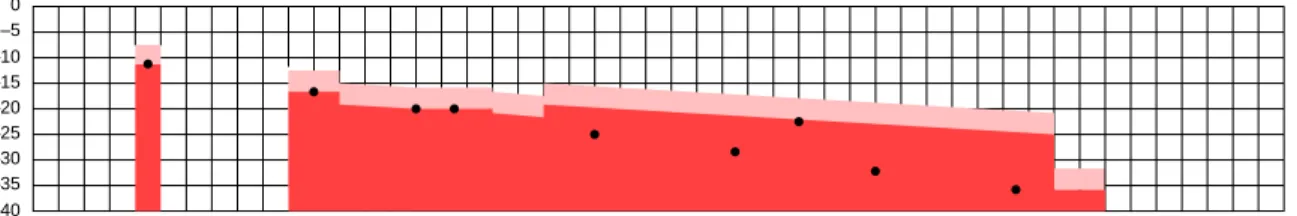
Fig. 10 illustrates the impulse response of the ref-erence channel model of the SMATV network. The X-axis represents the echo delay between de-vices on consecutive floors and the Y-axis gives the echo attenuation. Results of studies recently carried out by the Euro-Image Project conclude that a similar model can also be applied to CATV networks and, therefore, the equalization require-ments for user-IRDs are the same for both CATV and SMATV installations.
The reference channel model for most practical installations is marked with “3 sigma”8 and is
rep-resented in Fig. 10 by dark shading. The light-shaded area on the diagram refers to the worst-case situation.
8. Three times the standard deviation () from the mean conditions. –40 –35 –30 –25 –20 –15 –10 –5 0 1 - 5 6 - 10 1 1 - 15 16 - 20 21 - 25 26 - 30 31 - 35 36 - 40 41 - 45 46 - 50 51 - 55 56 - 60 61 - 65 66 - 70 71 - 75 76 - 80 81 - 85 86 - 90 91 - 95 96 - 100 101 - 105 106 - 1 1 0 111 11 5 1 1 6 - 120 121 - 125 126 - 130 131 - 135 136 - 140 141 - 145 146 - 150 151 - 155 156 - 160 161 - 165 166 - 170 171 - 175 176 - 180 181 - 185 186 - 190 191 - 195 196 - 200 201 - 205 206 - 210 21 1 - 215 216 - 220 221 - 225 226 - 230 231 - 235 236 - 240 241 - 245 Relative delay (ns) Relative amplitude (dB) Worst case 3 sigma Key: Figure 10 RF channel response of UHF and S-band SMATV distribution networks.
After intensive investigations, it was concluded that SMATV systems require equalization in near-ly all cases where QAM signals are to be distrib-uted. However, although the use of equalization is mandatory, it was concluded that simple equaliza-tion structures would be enough to cope with the short-term echoes that are generated in SMATV distribution systems with cable lengths of no more than several tens of metres.
Adaptive “blind” equalizers, composed of a sym-bol-spaced complex transversal FIR9 filter, were successfully tested by means of computer simula-tion. Half-symbol-spaced equalizers showed an even better performance. The minimum equalizer length should be of about 6 taps, while 8 to 10 taps could offer an additional margin to cope with longer echoes. The convergence time of the equal-ization algorithms were found to be very low – in the range of a few milliseconds.
Residual signal-to-noise degradation – for a BER of 2.10-4 (before Reed-Solomon correction) – was
evaluated by means of a computer simulation of 1000 different “3 sigma” SMATV channels, in the case of symbol-spaced and half-symbol-spaced equalizer configurations with 4, 5 and 6 taps. It was concluded that with 6 taps in the equalizer, the losses with respect to the ideal behaviour are smaller than 1.5 - 2 dB in all practical cases.
7. Other DVB systems 7.1. DVB-T
The DVB terrestrial system (DVB-T) is now evolving towards a commercial stage of develop-ment, as already achieved by the DVB satellite and
9. Finite impulse response.
cable systems. The draft baseline DVB-T system has already been produced.
For transmission via 8-MHz terrestrial channels, the practical upper limit on the bit-rate is about 24 Mbit/s; the actual useful bit-rate depends on the error correction and the type of modulation system used.
The baseband elements are based on the MPEG-2 coding system. A number of different configura-tions are possible, ranging from simple arrange-ments with a number of channels of conventional quality, to more sophisticated arrangements which involve multiple levels of coding and modulation. The DVB-T signal is common with the other DVB systems. Nevertheless, an innovative modulation concept is used – OFDM – which is described in the article starting on page 39 [11].
7.2. DVB-MMDS
Another transmission system being studied by the DVB Project is Microwave Multipoint Distribu-tion System (MMDS). The same philosophy is be-ing applied to this system: a common payload and harmonized data container will be adapted to suit the physical characteristics of the MMDS trans-mission medium.
The DVB system for MMDS distribution is at the final phase and it is likely that it will comprise two configurations:
– DVB-MS, which will be common with DVB-S and will be suitable for frequencies above 10 GHz;
– DVB-MC, which will be common with DVB-C and will be suitable for frequencies below 10 GHz.
Dr. Julián Seseña is the Telecommunications Manager at Hispasat. He is responsible for the
telecommu-nications tasks that are associated with the operation of the Hispasat satellite system: frequency coordination, the specifications of satellite and earth stations, technology, transmission plans, etc. Julián Seseña graduated in Telecommunications Engineering in 1985. He has a Ph.D in Radiocommuni cations and an M.Sc covering subjects such as European Communities, Advanced Telecommunication Services, Business Marketing Management, etc.
Dr. Seseña represents Hispasat on various committes including DVB-TM, ETSI, DAVIC, ITU-R and ITU-T. He also participates in various EBU committees. He is Project Manager of the RACE project DIGISMATV and the follow-up ACTS project, DIGISAT.
8. Interoperability and interconnectivity
In the previous sections, the main elements which form the basis of each DVB system have been de-scribed. It can be seen that most of the key ele-ments are common to all the DVB systems, partic-ularly the video and audio source coding, the multiplex and framing structure, and the Reed-Solomon outer coding. Any divergences from the norm (i.e. “peculiarities”) mainly relate to the physical characteristics of the individual delivery medium, e.g. the modulation scheme used, the error protection required and the frequency range used. More information on this is given in [12]. This intelligent strategy allows the interconnec-tion of different delivery media to provide an inte-grated broadcasting service, and also facilitates the achievement of economies of scale due to the fact that core elements of each DVB system are com-mon. Another important aspect is that the DVB signals can transit through different transmission media in a seamless way, which greatly increases the availability of cost-effective solutions for digi-tal television broadcasting.
9. Future trends
Extensive new television services are becoming available to the user, as a result of the rapidly-developing digital technologies. The current DVB systems for satellite, cable and terrestrial distribu-tion of digital television will soon allow interactive capabilities which, based on different levels of user participation, may bring new business opportunities. The definition of a specification for the DVB inter-action channel (i.e. the return channel) will allow the implementation of an interactive return path to the service provider, thus enabling new types of broadcasting services to be provided. For example, a user of such interactive equipment would be able to participate directly in a programme from home. The first interactive services will be of the asym-metrical type. This means that the user will receive the broadcast signal via a broadband channel, com-plete with information on the subject content of the service; at the same time, the user will be able to interact with the broadcaster, or programme pro-vider, by sending low bit-rate messages along a narrowband return channel.
The DVB key to success – the monitoring of mar-ket needs and the commonality of sub-systems between different media solutions – will also be
retained during the process of defining the overall interaction channel. The production of suitable specifications for the interaction channel is being carried out by the Technical Module of the DVB through a specialized ad-hoc group, the DVB-RC. Commonality with other systems being defined by international bodies, such as DAVIC10, are being assessed (see the article starting on page 50 [13]). Priority has been given in DVB to the definition of the return channel through PSTN11 and CATV net-works. Technological projects, under the umbrella of the ACTS12 programme of the European Union (DIGISAT, INTERACT, ISIS), will provide key results to support the definition of reliable techni-cal specifications for satellite and terrestrial re-turn-channel systems.
In conclusion, the DVB family of systems today allows the provision of digital broadcasting ser-vices via the most popular delivery media current-ly available; these systems satisfy the particular needs of the broadcasters, the users and, most crucially, the marketplace.
The future will bring new opportunities with the upgrading of DVB systems to include an inter-action channel, thus allowing digital broadcasting to go “interactive” and hence give birth to the “active user”.
Bibliography
[1] ETS 300 421: Digital broadcasting systems
for television, sound and data services; Framing structure, channel coding and modulation for 11/12 GHz satellite ser-vices.
ETSI, May 1995.
[2] ETS 300 429: Digital broadcasting systems
for television, sound and data services; framing structure, channel coding and modulation for cable systems.
ETSI, May 1995.
[3] ETS 300 473. Digital broadcasting
sys-tems for television, sound and data ser-vices; Satellite Master Antenna Television (SMATV) distribution systems.
ETSI, May 1995.
[4] ISO/IEC CD 13818, Part I: Coding of moving
pictures and associated audio. Part 1: Systems.
ISO/IEC, November 1993.
10. Digital Audio Visual Council. 11. Public Switched Telephone Network. 12. Advanced Communications, Technologies and
[5] ETR 154: Digital Video Broadcasting
(DVB): Implementation guidelines for the use of MPEG-2 systems, video and audio in satellite and cable applications in Europe.
DVB Project Office, European Broadcasting Union, Geneva.
[6] Going ahead with Digital Television
– Digital Video Broadcasting.
DVB Project Office, European Broadcasting Union, Geneva.
[7] Evaluation report on the performance of
the DVB system on real satellites.
Euro Image project M1003/HIS/SAT/DS/ R/341.
HISPASAT, October 1995.
[8] Stenger, L.: The European DVB cable
system.
Proceedings of the IAB Seminar on Digital Television Broadcasting, Montreux, October 1994.
[9] Childs, I.: Channel coding and modulation
systems for digital television.
Proceedings of the IAB Seminar on Digital Television Broadcasting, Montreux, October 1994.
[10] Seseña, J.: The European SMATV DVB
System.
Proceedings of the IAB Seminar on Digital Television Broadcasting, Montreux, October 1994.
[11] Møller, L.G.: Digital terrestrial television –
The 8k system.
EBU Technical Review No. 266 (Winter 1995).
[12] Seseña, J.: Commonalities and
peculiari-ties of DVB-S, DVB-C and DVB-SMATV systems.
Proceedings of IBC’95, Amsterdam, September 1995.
[13] Chiariglione, L.: Digital Audio-Visual
Council – Rationale and goals.
EBU Technical Review No. 266 (Winter 1995).
Further reading:
Reimers, U.: Development and
standard-ization of DVB within the European project on digital video broadcasting.
Proceedings of the IAB Seminar on Digital Television Broadcasting, Montreux, October 1994.
Cominetti, M. and Morello, A.: The European
satellite DVB system for the 11/12 GHz services
Proceedings of the IAB Seminar on Digital Television Broadcasting, Montreux, October 1994.
DVB-TM 1189: Potential applications of the
baseline modulation/channel coding sys-tem for digital multiprogramme television by satellite.
DIGISMATV NT-DI-031-HSA: Satellite
digi-tal TV in collective antenna systems: SMATV reference channel model for digi-tal TV.
DIGISMATV Project, July and October 1994. Gavilan, E.: Aplicaciones de la Televisión
Digital a la Transmisión por Satélite.
Instituto Oficial de Radio Televisión Española, 1995.
Writing for the EBU Technical Review
The Review welcomes articles from broadcasting organizations, broadcast research institutes and the broadcast manufacturing industry.
Our readers are interested in theoretical studies, explanations of new
techniques, descriptions of major engineering development projects, reports on the broadcast coverage of large-scale events, etc.
The EBU Technical Review is distributed to the engineering divisions of all the EBU Active and Associate Member-organizations throughout Europe and the rest of the world. It also has wide circulation among broadcast equipment manufacturers, universities and other specialist institutions.
For an Author’s Information Pack, please contact: The Editor EBU Technical Review Case postale 67 CH-1218 Grand Saconnex (GE)