driller aimed at improving
its machining efficiency*
Projekt opremanja vi{evretene bu{ilice radi
pove}anja njezina u~inka*
Professional paper • Stru~ni rad
Prispjelo - received: 7. 11. 2005. • Prihva}eno - accepted: 25. 4. 2006. UDK: 630*823.126; 674.055:621.95
ABSTRACT • The basic element of each multiple-spindle driller is its working unit also called drilling head. The use of multi-spindle drill heads enables simultaneous drilling of holes arranged in rows, which makes such drillers much more efficient than one-spindle drillers. However their defect is the lack of possibility to make holes in stud elements. Passage drillers are particularly affected by this problem and this is why research on this machine-too-ling was undertaken. The project enables widening technological possibilities of multiple-spindle /gang/ drilmachine-too-ling machines. This paper deals with the presentation of some types of tooling.
Key words:multiple-spindle drilling machine, instrumentation, effectiveness
SA@ETAK• Osnovni dio svake vi{evretene bu{ilice jest njezina radna jedinica koja se naziva glava za bu{enje. Uporaba vi{evretenih bu{ilica omogu}uje simultano bu{enje rupa u redovima, {to ~ini takve bu{ilice u~inkovitijima od jednovretenih bu{ilica. No njihov je nedostatak nemogu}nost bu{enja rupa u ~etvrtastim drvnim elementima. To je osobito velik problem kad je rije~ o bu{ilicama za prolazne provrte, {to je razlog da se u podru~ju te vrste obrade provode intenzivna istra`ivanja. Projekt pridonosi pro{irenju tehnolo{kih mogu}nosti vi{evretenih bu{ilica, a u radu se razra|uju neke mogu}nosti njihova opremanja.
Klju~ne rije~i:vi{evretena bu{ilica, opremanje, u~inak
1 INTRODUCTION 1. UVOD
Multiple-spindle drillers can be included into basic woodworking machines used in furniture industry; howe-ver their machining range is limited to making holes and most frequently for dowel or screw connections (Kien, 2003; Lisican et al, 1996; Siklienka and Sajbanova, 2002). Drilling of holes’ sockets is still one of the basic technological operations performed in furniture
in-dustry. Dowel joints, commonly used in furniture con-structions, and different kinds of fittings, which require performing of various sockets and holes, basically can be divided into:
– constructional (e.g. dowel connections, Confirmat screw connections)
– for fitting (e.g. holders, locks, hinges (fig.1)) Speaking of drilling, in a considerable number of cases of standard machining, the so called series dril-1
Authors are assistant professor and assistant at the Agricultural University in Poznan, Poland.
1
Autori su docent i asistent na Poljoprivrednom sveu~ili{tu u Poznanju, Poljska. * Rad je pripremljen za sastanak Interkatedra 2005 „Woodworking technique” * The paper was prepared for meeting Interkatedra 2005 „Woodworking technique”
ling can be encountered. In such cases holes are arran-ged in rows, usually in straight line.
Wide application of wood product boards espe-cially in constructions of cabinet furniture resulted in a wide use of joint hinges (e.g. eccentric joints). Such jo-ints require many series drillings and compound dril-lings (Fig. 2). All the above mentioned aspects have re-sulted in a dynamic development of multi-spindle dril-ling machines.
Multiple-spindle drillers can be divided into two groups (Lisi~an et al, 1996; Siemiñski, 1991):
– passage – used in production lines
– cyclic – used for small series; flexible approach to furniture production.
The most important part of each multi-spindle dril-ler is its working unit - the drildril-ler head (Fig. 5). The effi-ciency of this type of heads in such machines has been considerably improved and the machining time shorte-ned in comparison to one-spindle drillers (Fig. 6).
Increasing application of dowel and metal joints (e.g. Confirmat screws) in skeleton constructions made impossible the use of one-spindle drillers with conven-tional equipment. This can be illustrated by drilling in Figure 1An example of door hinges
Slika 1.Primjer vratnih {arki
Figure 2Examples of drillings in furniture units
Slika 2.Primjer bu{enja dijelova namje{taja
Figure 3Cyclic multiple-spindle drillers (Vitap- Italy)
Slika 3.Cikli~ne vi{evretene bu{ilice (Vitap- Italija)
Figure 4 Passage multiple-spindle drillers (Biesse- Italy)
Slika 4.Vi{evretene bu{ilice za prolazne rupe (Biesse- Italija)
Figure 5Example of head passage of multiple-spindle driller
Slika 5.Glava vi{evretene bu{ilice za prolazne rupe
Figure 6One-spindle driller
narrow units especially in the fronts (Kien,1996; Kien, 2003; Kien, 2000; Osajda and Wieloch, 2005).
Sometimes there are situations when holes are drilled in ++ areas lying at an angle to other surfaces of the machined object (e.g. when units are connected by splayed joints). Although there is a possibility of head adjustment to different angles (e.g. 45°), difficulties arise in positioning and fixing the machined objects. It enables a wider use of standard cyclic multi-spindle driller instead of an expensive specialised one (Fig. 7).
Further to the above reasons, in a furniture factory which has no specialised cyclic multi-spindle driller (e.g. Fig. 7) at its disposal, the holes in units are drilled one by one by a one-spindle driller (Fig. 6) or by a hori-zontal drill-moulder. However, this is a labour consu-ming method with low efficiency, and what is more it often requires the use of special equipment.
Arrangement and number of heads and spindles in these heads in majority of multi-spindle drillers en-courage their use in atypical machining operations especially in drilling holes in scantling units with the use of additional equipment.
Based on the above considerations, a project of special instrumentation was elaborated in the Depar-tment of Woodworking Machinery and Basis of Machi-ne Construction at the Agricultural University in Poz-nañ aimed at improving technological possibilities of holes drilling in scantling units.
2 CONCEPT AND DESIGN OF INSTRUMENTATION
2. KONCEPT I RAZVOJ OPREME
Before developing the design, the following fore-designs were made (Dobrzañski, 1981; Kien, 2003; Osajda and Wieloch, 2005):
– Adjustment of the design of DCWGW - 19 mul-ti-spindle driller (Polish product).
– Enabling drilling of holes with skew axes (angle ran-ge from 30° to 75°), situated on the surface of square timbers usually at the axis distance smaller than mo-dule “32”.
– Machining of several units simultaneously.
– Adding instrumentation consisting of one or several components. The application of suggested solutions provides no adaptation of the drilling machine. – Adjustment of drilling to work with instrumentation
depends on limited disassembly, or change of loca-tion of its components. Quick return to the basic ver-sion of the machine should be possible any time. – Utilization of the existing fixing system (Osajda and
Wieloch, 2005).
3 PROJECT RESULTS 3. REZULTATI PROJEKTA
3.1 Holder of cyclic multi-spindle driller 3.1. Dr`a~ cikli~ne vi{evretene bu{ilice
The most important element of instrumentation shown in Figure 10 is a movable system of two boards consisting of the footing (Dobrzañski, 1981) and upper Figure 7 Specialised cyclic multiple-spindle machine
(Knoevenagel - Germany)
Slika 7.Specijalizirana cikli~na vi{evretena bu{ilica (Knoevenagel - Njema~ka)
Figure 8Examples of holes drilled in scantlings - square timber
Slika 8.Primjer rupa izbu{enih u ~etvrta~ama
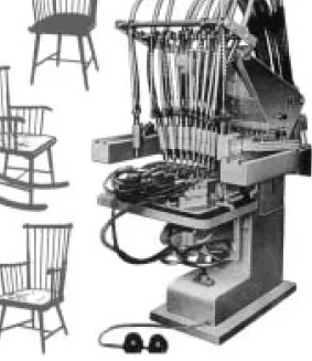
Figure 9 Cyclic multi-spindle drilling machine - type DCWGW-19
board (Kien, 1996). The footing of the holder, made of MDF board, is used for fastening the holder to the work table of the drilling machine. The upper board - also made of MDF board – is equipped with support blades (Kien, 2003) and blade clamps (Kien, 2000) that can be regulated.
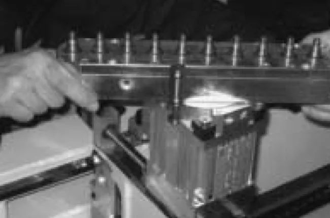
After fixing tightly the holder to the machine body and providing appropriate deflection of the upper board, depending on machining conditions, machined units have to be put in the right place. The instrumenta-tion enables simultaneous drilling of five units. The machined objects are inserted from the top between the support blades and blade clumps. The spring situated in the clamp body causes pressure on pressure blade, which enables its movement in a pre-set range and its constant contact with the machined unit. The heads of machined units have to be adequately pushed to the re-sistance blade of the machine as shown in Figure 10. After fixing the units, the drilling operation of all units starts simultaneously. During the drilling cycle, the units are immobilized by pneumatic clamps of the dril-ling machine with pressure blades.
After having performed the sockets, the driller heads withdraw to the initial position after which
ma-chined units are removed and the next units are inserted into the holder. The following drilling cycles are per-formed in the same way as described above.
4 CONCLUSION 4. ZAKLJU^AK
1. The designed holder of DCWGW- 19 cyclic mul-ti-spindle driller enables drilling of holes at angles from 30° to 75° to surface areas of square timber units. 2. Taking into consideration the vertical movement of the working unit in the range of 60 mm, there is a possibility - after having used the holder – of dril-ling holes in skew surfaces at optional distances. 3. The holder enables drilling of non-square timber
units of the following dimensions: (20-100) x (20-100) x (200-500); the drilling operation of all (5) units starts simultaneously.
5 REFERENCES 5. LITERATURA
1. Dobrzanbski, T. 1981: Uchwyty obróbkowe. Poradnik konstruktora. WNT, Warszawa.
Figure 10 Prototype instrumentation of cyclic multi-spindle drilling machine
Slika 10.Prototip opreme za cikli~ne vi{evretene bu{ilice
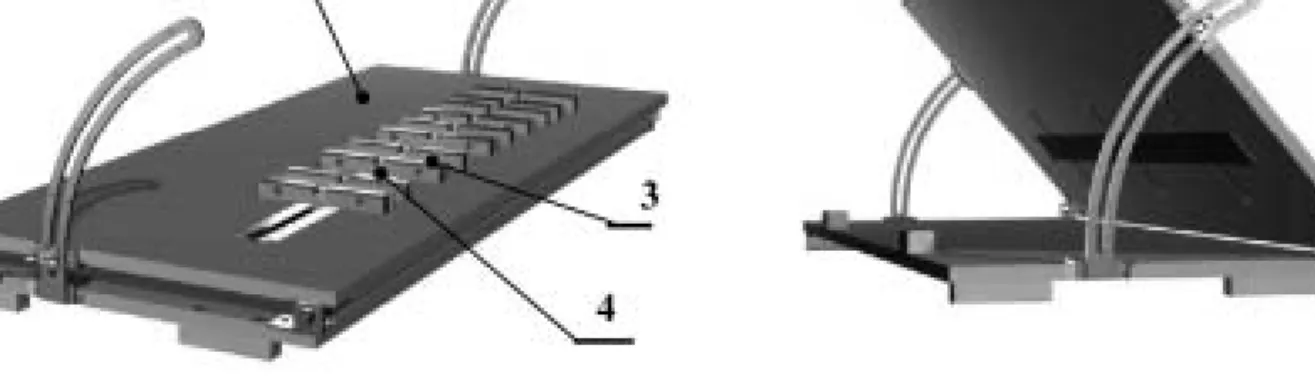
Figure 11 Simulation of use of instrumentation of cyclic multi-spindle drilling machine
6. Informative materials and folders of firms: Alberti, Bies-se, Homag, Gomad, Weeke, Morbidelli, Vitap, SCM, Nottmeyer, Knoevenagel, Festo.
7. Lisican et al. 1996: Teoria a technika spracovania dreva. Mat –Centrum, Zvolen
8. Meier, G. 1997: Spanabhebende Maschinen in der Hol-zverarbeitung.
9. Osajda, M., Wieloch, G. 2005: Adaptations of multi-ple-spindle drillers resulting in expanding their machi-ning possibilities. 3. International PhD Conference on Mechanical Engineering. PhD 2005, Westbochemia Tec-hnical University, Pilzno
Corresponding address:
Assist. Prof. GRZEGORZ WIELOCH, PhD. Agricultural University in Poznan
Chair of Machining and Basis of Machine Construction ul. Wojska Polskiego 38/42
60-627 Poznanb, Poland e-mail: obrawielºau.poznan.pl