5114VU
Trademarks
All brand and product names are trademarks or registered trademarks of their respective companies.
Note
Caution Texts Concerning Lithium Batteries
DANISHADVARSEL!
Lithiumbatteri - Eksplosionsfare ved fejlagtig håndtering. Udskiftning må kun ske med batteri af samme fabrikat og type. Levér det brugte batteri tilbage til
leverandøren.
NORWEGIAN ADVARSEL:
Eksplosjonsfare ved feilaktig skifte av batteri. Benytt samme batteritype eller en tilsvarende type anbefalt av apparatfabrikanten. Brukte batterier kasseres i henhold til fabrikantens instruksjoner.
SWEDISH VARNING:
Explosionsfara vid felaktigt batteribyte. Använd samma batterityp eller en ekvivalent typ som rekommenderas av apparattillverkaren. Kassera använt batteri enligt fabrikantens instruktion.
FINNISH VAROITUS:
Paristo voi räjätää, jos se on virheellisesti asennettu. Vaihda paristo ainoastaan valmistajan suosittelemaan tyyppiin. Hävitä käytetty paristo valmistajan ohjeiden mukaisesti.
ENGLISH CAUTION:
Danger of explosion if battery is incorrectly replaced. Replace only with the same or equivalent type recommended by the equipment manufacturer. Discard used batteries according to manufacturer's instructions.
Class B Regulations
U. S. A.Federal Communications Commission Radio Frequency Interference Statement
This equipment has been tested and found to comply with the limits for a Class B digital device pursuant to Part 15 of the FCC Rules. These limits are designed to provide reasonable protection against harmful interference in a residential installation. This equipment generates, uses, and can radiate radio frequency energy and, if not installed and used in accordance with the instructions, may cause harmful interference to radio communications. However, there is no guarantee that interference will not occur in a particular installation. If this equipment does cause harmful interference to radio or television reception, which can be determined by turning the equipment off and on, the user is encouraged to try to correct the interference by one or more of the following measures:
– Reorient or relocate the receiving antenna.
– Increase the separation between the equipment and receiver. – Connect the equipment into an outlet on a circuit different from that to which the receiver is connected.
– Consult the dealer or an experienced radio/TV technician for help.
Warning:
Use only shielded cables to connect I/O devices to this equipment.
You are cautioned that changes or modifications not expressly approved by the party responsible for compliance could void your authority to operate the equipment.
Canada
Canadian Department Of Communications Radio Interference Regulations Class B Compliance Notice
This digital apparatus does not exceed the Class B limits for radio noise
emissions from digital apparatus set out in the Radio Interference Regulations of the Canadian Department of Communications.
Le présent appareil numérique n'émet pas de bruits radioélectriques dépassant les limites applicables aux appareils numériques de la classe B prescrites dans le Règlement sur le brouillage radioélectrique édicté par le ministère des Communications du Canada.
Important Safety Instructions
• Read all of these instructions.
• Follow all warnings and instructions marked on the product.
• Unplug this product from the wall outlet before installing an add-on card inside this product.
• Do not use this product near water.
• Do not place this product on an unstable cart, stand, or table. The product may fall, causing serious damage to the product.
• Slots and openings in the cabinet are provided for ventilation. To ensure reliable operation of the product and to protect it from overheating, these openings must not be blocked or covered. The openings should never be blocked by placing the product on a bed, sofa, rug, or other similar surface. This product should never be placed near or over a radiator or heat register. This product should not be placed in a built-in installation unless proper ventilation is provided.
• This product should be operated from the type of power source indicated on the marking label. If you are not sure of the type of power available, consult your dealer or local power company.
• This product is equipped with a 3-wire grounding-type plug, a plug having a third (grounding) pin. This plug will only fit into a grounding-type power outlet. This is a safety feature. If you are unable to insert the plug into the outlet, contact your electrician to replace your obsolete outlet. Do not defeat the purpose of the grounding-type plug. We recommend using the power cord supplied with the product. However, if another type of power cord is required, power cord H05VV-F should be used.
• Do not allow anything to rest on the power cord. Do not locate this product where persons will walk on the cord.
• Except as explained elsewhere in this manual, do not attempt to service this product yourself.
Table of Contents
Preface ... 9
Chapter 1 Introduction... 10
Features ...10
Specifications ...10
CPU, Memory, and Main Components ...10
Interfaces and Controllers...11
Chapter 2
System Components ... 12
Major Components...12
Chapter 3 Connector and Jumper Definition... 16
Connector Definitions...17
Internal Connectors...17
External Connectors ...17
Jumper Settings ...18
AMD K6 Jumper Settings...18
Other Jumper Settings ...18
Chapter 4
CPU and Memory Installation... 19
CPU Installation ...19
System Memory Installation ...21
Chapter 5
The SETUP Program ... 23
Introduction ...23
Starting SETUP...23
Moving Around and Making Selections...24
Standard CMOS Features...25
Advanced BIOS Features ...26
Advanced Chipset Features...28
Integrated Peripherals...28
Power Management Setup...30
PnP/PCI Configurations ...31
PCI Health Status...31
Load Fail-Safe / Optimized Defaults ...31
Set Supervisor Password/User Password ...32
Appendix A Software Drivers and Utilities ...33
Installation Instructions for Windows 98 ... 33
Audio Driver ... 33
Video Driver ... 33
Installation Instructions for Windows NT 4.0 ... 34
Audio Driver ... 34
List of Figures
Figure 2-1. Major Components of System Board...12
Figure 3-1. Connector and Jumper Locations...16
Figure 4-1. Inserting CPU ...19
Figure 4-2. Installing CPU ...20
Figure 4-3. DIMM Socket Locations...21
Figure 4-4. Installing DIMM Module ...22
List of Tables
Table 2-1. Major Components Description ...13Table 3-1. Internal Connector Definition ...17
Table 3-2. External Connector Definition ...17
Table 3-3. CPU Jumper Settings ...18
Table 3-4. CMOS Jumper Settings ...18
Preface
This manual contains basic information necessary for both the end user and service personnel. Although most of the information you need are contained in this manual, we recommend you to contact an authorized dealer for service purposes. Making personal alterations to the system can violate the effectivity of your warranty.
This manual is divided into five chapters and one appendix.
• Chapter 1, Introduction, lists the specifications and features of the motherboard.
• Chapter 2, System Components, describes the functions of the major system components.
• Chapter 3, Connector and Jumper Definition, provides the jumper and connector definitions.
• Chapter 4, CPU andMemory Installation, contains the CPU and memory installation information.
• Chapter 5, The SETUP Program, explains how you can configure your system by running the SETUP program.
• Appendix A, Software Drivers and Utilities, describes how to install the drivers and utilities supplies with your system.
Chapter 1
Introduction
This chapter introduces the specifications and the features of the motherboard.
Features
• Socket 7
For AMD K6-2 / K6 III CPU • Plug and Play support
For automatic resource assignment, your system is PnP version 1.01a compliant.
• Audio subsystem
The audio subsystem allows you to easily record, play, and edit music and voice.
• Video subsystem
The video subsystem allows you to easily play video CD, clip files and 3D games.
• USB port support
The Universal Serial Bus standard gives you the benefits of having one single interface for multiple interfaces when low-to-medium speed peripherals are concerned.
• Power Management
Your system can reduce power consumption automatically while it is idle. It also supports the Windows 98/Windows NT 5.0 power management standard - ACPI (Advanced Configuration Power Interface).
Specifications
CPU, Memory, and Main Components
• CPU
AMD K6-2 / K6 III series CPU • System Memory
Two 168-pin DIMM sockets to support 8/16/32/64/128/256MB SDRAM memory modules, configurable up to 512MB
• Cache
512KB cache memory • ROM BIOS
2Mb flash EEPROM, supporting audio, video, security, setup, and power management
Interfaces and Controllers
• VIA MVP4 chipset
The chipset consists of the VT82C8501 north bridge and the VT82C686A PCI Super I/O Integrated Peripheral controller.
• Audio Controller
ESS ES1989 audio controller, compatible with Sound Blaster Pro and Windows Sound System
• Video Controller
AGP controller (integrated in VT82C8501), supporting 2.0 AGP Interface and 64-bit graphics with video acceleration
• I/O Interfaces
TheVT82C686A controller supports:
−−−− One standard/ECP/EPP parallel port (DB25-F) −−−− One RS-232C serial port (DB9-M)
−−−− One PS/2 keyboard connector (6-pin mini-DIN) −−−− One PS/2 mouse connector (6-pin mini-DIN) −−−− One VGA port (DB15-F, 3-rows)
−−−− One game/MIDI port (DB15-F, 2-rows) −−−− Two USB connectors on the rear panel
−−−− Three audio ports for Line-in/Mic-in/Line-out (jack) −−−− Two PCI-IDE connectors for four IDE devices (jack) −−−− One floppy disk drive connector (jack)
• Expansion Slots
Chapter 2
System Components
This chapter introduces the components of the motherboard.
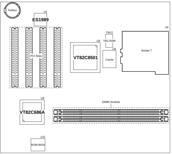
Major Components
Figure 2-1. Major Components of System Board
DIMM Sockets Socket 7 U6 U5 U9 U1 U11 U4 TAG1 VT82C686A ROM BIOS ES1989 VT82C8501 TAG RAM Cache PCI Slots
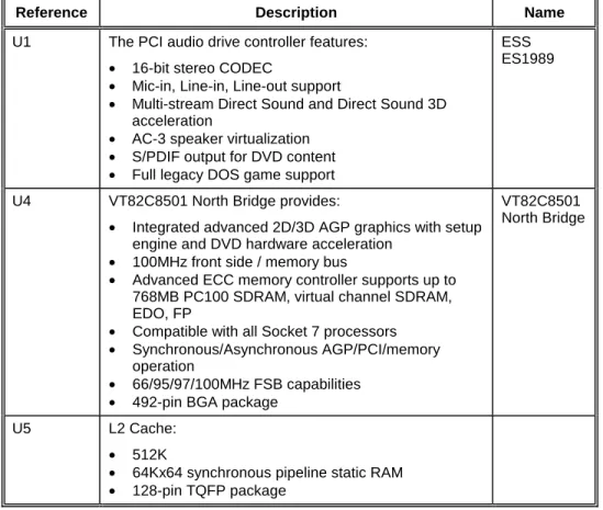
Reference Description Name
U1 The PCI audio drive controller features:
• 16-bit stereo CODEC
• Mic-in, Line-in, Line-out support
• Multi-stream Direct Sound and Direct Sound 3D acceleration
• AC-3 speaker virtualization
• S/PDIF output for DVD content
• Full legacy DOS game support
ESS ES1989
U4 VT82C8501 North Bridge provides:
• Integrated advanced 2D/3D AGP graphics with setup engine and DVD hardware acceleration
• 100MHz front side / memory bus
• Advanced ECC memory controller supports up to 768MB PC100 SDRAM, virtual channel SDRAM, EDO, FP
• Compatible with all Socket 7 processors
• Synchronous/Asynchronous AGP/PCI/memory operation
• 66/95/97/100MHz FSB capabilities
• 492-pin BGA package
VT82C8501 North Bridge
U5 L2 Cache:
• 512K
• 64Kx64 synchronous pipeline static RAM
• 128-pin TQFP package
(To be continued)
(Continued)
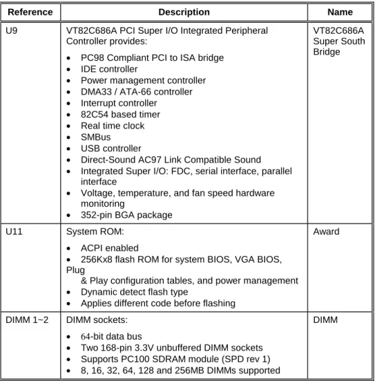
Reference Description Name
U9 VT82C686A PCI Super I/O Integrated Peripheral Controller provides:
• PC98 Compliant PCI to ISA bridge
• IDE controller
• Power management controller
• DMA33 / ATA-66 controller
• Interrupt controller
• 82C54 based timer
• Real time clock
• SMBus
• USB controller
• Direct-Sound AC97 Link Compatible Sound
• Integrated Super I/O: FDC, serial interface, parallel interface
• Voltage, temperature, and fan speed hardware monitoring
• 352-pin BGA package
VT82C686A Super South Bridge
U11 System ROM:
• ACPI enabled
• 256Kx8 flash ROM for system BIOS, VGA BIOS, Plug
& Play configuration tables, and power management
• Dynamic detect flash type
• Applies different code before flashing
Award
DIMM 1~2 DIMM sockets:
• 64-bit data bus
• Two168-pin 3.3V unbuffered DIMM sockets
• Supports PC100 SDRAM module (SPD rev 1)
• 8, 16, 32, 64, 128 and 256MB DIMMs supported
DIMM
(To be continued)
(Continued)
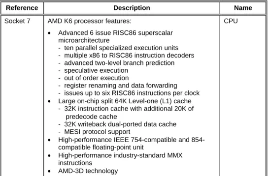
Reference Description Name
Socket 7 AMD K6 processor features:
• Advanced 6 issue RISC86 superscalar microarchitecture
- ten parallel specialized execution units - multiple x86 to RISC86 instruction decoders - advanced two-level branch prediction - speculative execution
- out of order execution
- register renaming and data forwarding - issues up to six RISC86 instructions per clock
• Large on-chip split 64K Level-one (L1) cache - 32K instruction cache with additional 20K of predecode cache
- 32K writeback dual-ported data cache - MESI protocol support
• High-performance IEEE 754-compatible and 854-compatible floating-point unit
• High-performance industry-standard MMX instructions
• AMD-3D technology
CPU
Chapter 3
Connector and Jumper
Definition
This chapter defines the connectors and jumpers on the motherboard.
Figure 3-1. Connector and Jumper Locations
JP3 BAT1 CD1 GAME1 MIC-in Line-in Line-out VGA1 COM1 FAN1 PJ1 JP6 JP7 JP12 JP8 JP13 FAN2 J2 JP9 JP14 JP11 JP10 CN1 JP15 DIMM1 IDE1 IDE2 FDD1 DIMM2 JP4 JP5 USB1 PS1
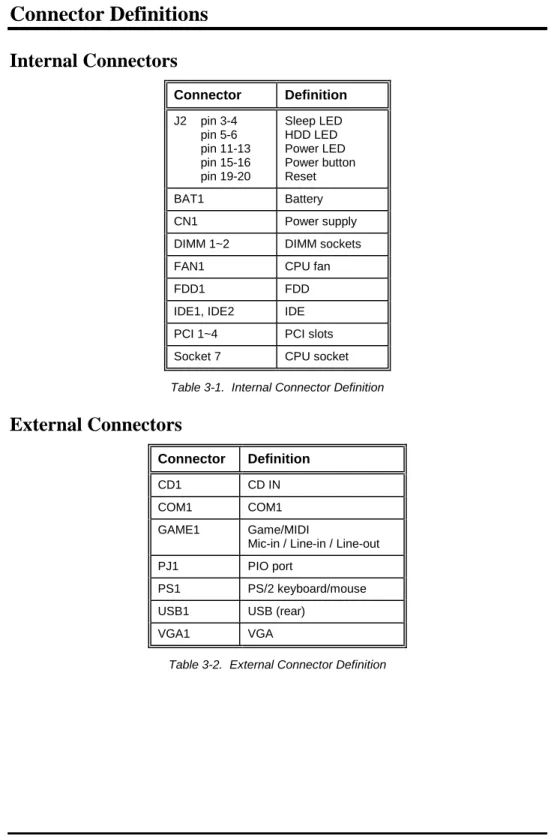
Connector Definitions
Internal Connectors
Connector Definition J2 pin 3-4 pin 5-6 pin 11-13 pin 15-16 pin 19-20 Sleep LED HDD LED Power LED Power button Reset BAT1 Battery CN1 Power supply DIMM 1~2 DIMM sockets FAN1 CPU fan FDD1 FDD IDE1, IDE2 IDE PCI 1~4 PCI slots Socket 7 CPU socketTable 3-1. Internal Connector Definition
External Connectors
Connector Definition
CD1 CD IN COM1 COM1 GAME1 Game/MIDI
Mic-in / Line-in / Line-out PJ1 PIO port
PS1 PS/2 keyboard/mouse USB1 USB (rear)
Jumper Settings
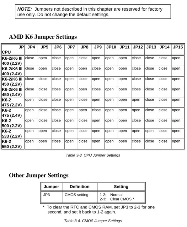
NOTE: Jumpers not described in this chapter are reserved for factory use only. Do not change the default settings.
AMD K6 Jumper Settings
JP CPU
JP4 JP5 JP6 JP7 JP8 JP9 JP10 JP11 JP12 JP13 JP14 JP15
K6-2/K6 III 400 (2.2V)
close open close open close open open open close close close open
K6-2/K6 III 400 (2.4V)
close open close open open close open open close close close open
K6-2/K6 III 450 (2.2V)
close close close open close open open open close close close open
K6-2/K6 III 450 (2.4V)
close close close open open close open open close close close open
K6-2 475 (2.2V)
open close close open close open open open open close close open
K6-2 475 (2.4V)
open close close open open close open open open close close open
K6-2 500 (2.2V)
open close close open close open open open close close close open
K6-2 533 (2.2V)
open open close open close open open open open open close open
K6-2 550 (2.2V)
open open close open close open open open close close close open
Table 3-3. CPU Jumper Settings
Other Jumper Settings
Jumper Definition Setting
JP3 CMOS setting 1-2: Normal 2-3: Clear CMOS *
* To clear the RTC and CMOS RAM, set JP3 to 2-3 for one second, and set it back to 1-2 again.
Chapter 4
CPU and Memory Installation
NOTE: To avoid damage during installation, you are advised to ask your dealer for help.
NOTE: Static electricity can destroy electronic devices. Whenever you handle any option outside of its protective packaging, first discharge any static electricity from your body by touching a protective grounding device or unpainted metal on the rear panel of the system unit.
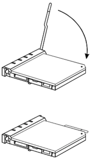
CPU Installation
To install CPU in the CPU socket:
1. Find Socket 7 (U6) on the motherboard. (See p.12.) 2. Lift the socket arm up to the vertical position.
3. Align the CPU so its Pin 1 corner (beveled corner) is at the Pin 1 corner of the socket. Then insert the CPU's pins into the corresponding holes in the socket.
4. Press the arm downwards to the horizontal position. You will feel some resistance while doing so. This is normal as the pressure starts to secure the CPU in place.
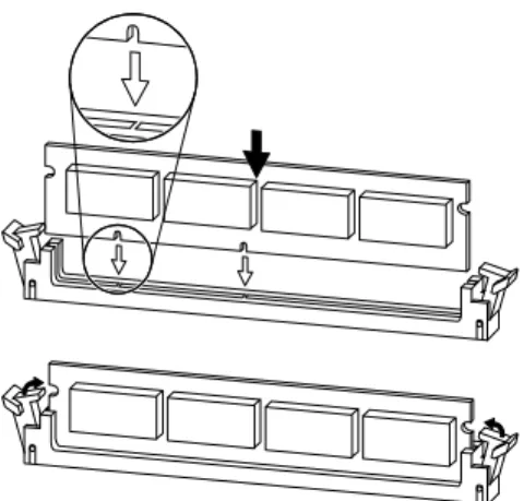
System Memory Installation
1. Locate the DIMM sockets (DIMM1 ~ DIMM2) on the motherboard.
DIMM Sockets TAG RAM
Cache
DIMM1 DIMM2
2. Align the DIMM module with the socket and firmly insert the DIMM into the socket. Then, push the plastic clips to snap it into place.
Chapter 5
The SETUP Program
This chapter tells you how to configure your system using the SETUP program.
Introduction
The SETUP program allows you to enter the system configuration information. This information is needed by the system to identify the type of devices installed and to set up special features.
The configuration information is stored in a special kind of memory called CMOS (Complementary Metal Oxide Semiconductor) RAM. CMOS RAM data are backed up by a RTC backup battery, so the data will not be lost when system power is turned off.
You need to run SETUP when:
• You see an error message on the screen requesting you to run SETUP. • You want to update the configuration information for new hardware installed. • You want to change factory default settings for some special features.
Starting SETUP
NOTE: The SETUP program may have been updated after this manual was published.
SETUP is built into the system board. To access the SETUP program, turn on the system and press [Del] immediately when you see the message that briefly appears at the bottom of the screen telling you how to enter SETUP.
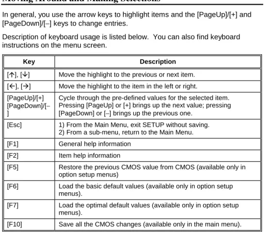
Moving Around and Making Selections
In general, you use the arrow keys to highlight items and the [PageUp]/[+] and [PageDown]/[−] keys to change entries.
Description of keyboard usage is listed below. You can also find keyboard instructions on the menu screen.
Key Description
[!], ["] Move the highlight to the previous or next item. [#], [$] Move the highlight to the item in the left or right. [PageUp]/[+]
[PageDown]/[− ]
Cycle through the pre-defined values for the selected item. Pressing [PageUp] or [+] brings up the next value; pressing [PageDown] or [−] brings up the previous one.
[Esc] 1) From the Main Menu, exit SETUP without saving. 2) From a sub-menu, return to the Main Menu. [F1] General help information
[F2] Item help information
[F5] Restore the previous CMOS value from CMOS (available only in option setup menus)
[F6] Load the basic default values (available only in option setup menus).
[F7] Load the optimal default values (available only in option setup menus).
[F10] Save all the CMOS changes (available only in the main menu).
Standard CMOS Features
The “Standard CMOS Features” category includes all the items in a standard, AT-compatible BIOS (Basic Input/Output System).
The followings describe in sequence all the items of this category.
Date/Time
The date and time might be incorrect when you start up your computer for the first time. Enter the correct value for each field. Note that the time is based on a 24-hour format.
IDE Primary/Secondary Master/Slave
This item sets the type of the hard disk drive in your computer. You can press [Enter] to go to the sub-items for settings.
Drive A/B
These items set the type of floppy disk drive in your computer.
Video
This item sets the type of display to be used in your computer.
Halt On
Advanced BIOS Features
The “Advanced BIOS Features” category includes all the items of your system’s special enhanced features.
The followings describe in sequence all the items of this category.
Virus Warning
This item helps prevent computer viruses by monitoring the boot sector and partition table of the hard disk drive. If an attempt is made to modify the boot sector and partition table, the system will halt and the following error message will appear. Afterwards, if necessary, you can run an anti-virus program to locate and remove the problem before any damage is done.
NOTE:
1. Disable this item before installing an operating system.
2. Many disk diagnostic programs can cause this warning message because they attempt to access the boot sector table. If you will be running such a program, you may want to disable this item
beforehand.
CPU Internal Cache, External Cache
This item enables or disables the cache of your system. The cache feature enhances system performance because the most frequently-used data is accessed from and written to the high-speed cache memory.
Quick Power On Self Test
This item, when enabled, speeds up the booting procedure by shortening or skipping some check items during POST.
First/Second/Third Boot Device, Boot Other Device
This item sets the sequence of booting, i.e., which drive to search first for the operating system.
Swap Floppy Drive
This feature allows you to exchange the drive names of the two floppy disk drives, if installed. Make sure that Drive A and Drive B item in the Standard CMOS Features menu are updated accordingly.
Boot Up Floppy Seek
This item sets if the system will verify the floppy disk drive type during POST.
Boot Up Numlock Status
This item sets if the Num Lock key will be automatically activated after system startup.
Gate A20 Option
This item uses the fast gate A20 line to access any memory above 1MB. Setting this item to make the access faster than the normal method.
Typematic Rate Setting
This item sets if the typematic rate is to be used. When disabled, continually holding down a key on your keyboard will generate only one instance. In other words, the BIOS will only report that the key is down. When the typematic rate is enabled, the BIOS will report as before, but it will then wait a moment, and, if the key is still down, it will begin the report that the key has been depressed
repeatedly. For example, you would use such a feature to accelerate cursor movements with the arrow keys.
When this item is set to Enabled, the following two sub-items appear.
Typematic Rate (Chars/Sec)
This item sets the rate (in characters/second) at which the keys are accelerated.
Typematic Delay (Msec)
This item sets the delay (in msecond) between when the key was first depressed and when the acceleration begins.
OS Select for DRAM > 64MB
This item allows you to access the memory that is over 64MB in OS/2.
Video BIOS Shadow
This item sets if the video BIOS will be copied to RAM to increase the video speed.
C8000-CBFFF Shadow
These items set if ROMs on an expansion card will be copied to RAM for faster speed. If you install an expansion card with ROMs, you need to know which addresses the ROMs use to shadow them specifically.
Advanced Chipset Features
The “Advanced Chipset Features” category includes all the items of chipset special features.
This category allows you to configure the system based on the specific features of the installed chipset. This chipset manages bus speeds and access to system memory resources, such as DRAM and the external cache. It also coordinates communications between the conventional ISA bus and the PCI bus. Note that these items should never need to be altered. The default settings have been carefully chosen by your system manufacturer to provide the absolute maximum performance and reliability.
Integrated Peripherals
The “Integrated Peripherals” category allows you to configure the on-board device controllers.
The followings describe in sequence all the items of this category.
OnChip IDE Channel 0/1
These item allow you to enable or disable the built-in IDE hard disk controller. Select Disabled only if you are using higher performance or specialized controller card instead of the onboard IDE controller.
IDE Prefetch Mode
Primary/Secondary Master/Slave PIO
Each of these four items sets the mode timing according to the IDE hard disk drives in your system. PIO means Programmed Input/Output. Rather than have the BIOS issue a series of commands to effect a transfer to or from the disk drive, PIO allows the BIOS to tell the controller what it wants and then let the controller and the CPU perform the complete task by themselves. This is simpler and more efficient (and faster). PIO mode concerns data transfer rate. It can be mode 0 to 4. Higher number indicates faster rate.
Primary/Secondary Master/Slave UDMA
These items set if the IDE hard disk drive supports UDMA (Ultra 33 synchronous DMA mode transfer).
IDE HDD Block Mode
This allows your hard disk controller to use the fast block mode to transfer data to and from your hard disk drive.
Onboard FDD Controller
This item allows you to enable or disable the on-board floppy disk drive controller.
Onboard Serial Port 1/2
This item sets the I/O address and interrupt request line (IRQ) for the on-board serial port (COM1/2).
Onboard Parallel Port
This item sets the I/O address and interrupt request line (IRQ) for the on-board parallel port (LPT1).
Power Management Setup
The “Power Management Setup” category allows you to configure you system to save energy.
The followings describe in sequence all the items of this category.
ACPI Function
This item enables or disables ACPI (Advanced Configuration Power Interface) -a power m-an-agement st-and-ard used by Windows 98 -and Windows NT 5.0.
Power Management
This item allows you to select the type (or degree) of power saving. You can press [Enter] to go to the sub-items for settings.
PM Control by APM
If the APM (Advanced Power Management) driver is installed, this item allows you to enable or disable control from APM.
Video Off Option
This item defines when the screen will be off.
Video Off Method
This item defines the screen-off status.
MODEM Use IRQ
This item defines the modem IRQ channel.
Soft-Off by PWRBTN
This item defines the Power/Suspend button of the system.
Wake Up Events
This group of items specify the I/O events that will wake up the system from a power saving mode. The system will remain alert for the activity of the device which is configured as Enabled. If you do not want a certain device activity to wake up the system, select Disabled for that device.
PnP/PCI Configurations
The “PnP/PCI Configurations” category allows you to configure the PnP/PCI bus system. PnP (Plug and Play) allows automatic allocation of the IRQ channel, memory address and I/O address for your system so that manual selection is not necessary. PCI (Personal Computer Interconnect) is a system which allows I/O devices to operate at speeds nearing the speed the CPU itself uses when communicating with its own special components.
NOTE: This setup menu is for technicians or advanced users only. You are not advised to change the default settings.
PC Health Status
This option lists the system status such as CPU temperature, system temperature, CPU fan speed, etc.
Load Fail-Safe / Optimized Defaults
If you select “Load Fail-Safe Defaults” or “Load Optimized Defaults” from the main menu, some default values will be loaded to the option setup menus such as Advanced BIOS Features, Advanced Chipset Features, Integrated
Peripherals, Power Management Setup, and PnP/PCI Configuration menus. The “Fail-Safe” default values have been set to assumedly provide minimum performance for the system. The settings are non-optimal and disable all high performance features.
The “Optimized” default values have been set to assumedly provide maximum performance for the system.
Set Supervisor Password/User Password
You can set either supervisor or user password, or both of them. The differences between them are:
• Supervisor password can enter and change the options of the setup menus. • User password can only enter but do not have the right to change the options
of the setup menus.
When you select this function, message will appear at the center of the screen to assist you in entering a password. Type the password and press [Enter]. Note the password is case-sensitive and can be up to eight characters in length. The password typed now will clear any previously entered password. You will be asked to confirm the password by typing it again and pressing [Enter]. To disable a password, just press [Enter] when you are prompted to enter the password. A message will confirm the password will be disabled. Once the password is disabled, the system will boot and you can enter SETUP freely. When a password has been enabled, you will be prompted to enter it every time you try to enter Setup. This prevents an unauthorized person from changing any part of your system configuration.
Additionally, when a password is enabled, you can also require the BIOS to request a password every time your system is rebooted. This would prevent unauthorized use of your computer.
You determine when the password is required within the “Advanced BIOS Features Setup” menu and its Security option (see “Advanced BIOS Features” in this chapter). If the Security option is set to System, the password will be required both at boot and at entry to Setup. If set to Setup, prompting only occurs when trying to enter Setup.
NOTE: If you forget your password and wish to cancel it, ask your dealer to reset the CMOS RAM for you.
Exiting Setup
To exit the SETUP program, you can choose “Save & Exit Setup” or “Exit Without Saving” from the main menu.
After finished with your settings, you must save and exit SETUP so that the settings can take effect.
Appendix A
Software Drivers and Utilities
This appendix describes the drivers and utilities used in your system. The drivers and utilities allow you to take advantage of special features of your system.NOTE: The driver and utility CD may have been updated after this manual was published. If your CD is different from that described in this appendix, refer to the README files on the CD. These files contain the latest information from the software supplier.
Installation Instructions for Windows 98
Audio Driver
The audio driver is required for using your system’s audio capabilities. To install the audio driver for Windows 98, follow these steps:
1. Insert the driver and utility CD into the CD-ROM drive.
2. Run the SETUP.EXE program in the \5114VU\AUDIO\WIN9598 directory on the driver and utility CD.
3. Follow the on-screen instructions.
Video Driver
The video driver is required for using your system’s video capabilities. To install the video driver for Windows 98, follow these steps:
3. Follow the on-screen instructions. You have to decompress the drivers and select the appropriate one according to your system specifications:
For AGP – AGPVXD32
For mini port - NIRQ-13
For APM - VIAREG14
NOTE: If you use a SCSI hard disk as a booting device, please add
rem c:\essaudio.com –blaster to the autoexec.bat file and
rem device=c:\essaudio.sys to the config.sys file.
Installation Instructions for Windows NT 4.0
Audio Driver
The audio driver is required for using your system’s audio capabilities. To install the audio driver for Windows NT 4.0, follow these steps:
1. In Windows NT, select “Control Panel”, “Multimedia”, and “Devices” tab. 2. Click on “Add” button.
3. Select “Unlisted or Updated Driver” and click on “OK”. 4. Insert the CD into the CD-ROM drive.
5. Specify the path \5114VU\AUDIO\NT4.0 on the CD, choose the driver from the list, and click on “OK”.
6. Follow the on-screen instructions. Select “Use Dual DMA” or “Enable MPU401” if you need these two features.
7. Restart the system.
Video Driver
The video driver is required for using your system’s video capabilities. To install the video driver for Windows NT 4.0, follow these steps:
1. In Windows NT, select “Control Panel”, “Display”, and then “Settings”. 2. Select “Display Type” and then “Change”.
3. Select “Hard Disk”.
5. Specify the path \5114VU\VGA\NT4.0 on the CD, and click on “OK”.
6. Follow the on-screen instructions. You have to decompress the drivers and select the appropriate one according to your system specifications:
For AGP – AGPVXD32
For mini port - NIRQ-13
For APM - VIAREG14
NOTE: If you use a SCSI hard disk as a booting device, please add
rem c:\essaudio.com –blaster to the autoexec.bat file and