Induction Motor Fault Diagnosis Using Microcontroller
Pratik Padmakar Sutar
Department Of Electrical Engineering, G. H. Raisoni Institute of Engineering &Technology, India.
I.
INTRODUCTION
Induction motors are widely used in many industrial applications. Due to the poor power quality and mechanical as well as thermal stresses the performance of the Induction Motor deteriorates. Early detection of the abnormal disturbances helps to keep down the forced maintenance cost and forced downtimes which impact more on production loss and loss of income.
As per the statistical study by the Electric Power Research Institute (EPRI), out of the total faults related to Induction motor, 41% are bearing related faults, stator faults account for 37%, rotor faults of 10% and other faults of 12%. Therefore, reliable system with continuous monitoring is essential for detection and diagnosis. Up till now various methods are used to analyze and counter the faults. In this approach, the fault is diagnosed by programming the microcontroller.
In this paper, the Cprogram feed into the controller detects the fault and immediately gives command to the relay to stop the motor. A LCD display is used to display the faults and to show real time current & voltage values. Over-current, Over-voltage, Under-voltage, and Ground fault could be diagnosed using this controller.
II.
T
HEF
AULTS A. Over VoltageWhen the motor is running in an overvoltage condition, slip will decrease as it is inversely proportional to the square of the voltage and efficiency will increase slightly. The power factor will decrease because the current being drawn by the motor will decrease and temperature rise will decrease because the current has decreased (based on I2t). As most new motors are designed close to the saturation point, increasing the V/HZ ratio could cause saturation of air gap flux causing heating.
The overall result of an overvoltage condition is an increase in current and motor heating and a reduction in overall motor performance.
So, we are taking reading from PT and set threshold value of voltage in the C program which is fed in the controller.If the voltage goes over threshold limit, the controller will command the relay to cutoff the supply from the motor.Overvoltage fault will be shown on the display mounted for the purpose.
B. Under Voltage
If an induction motor operating at full load is subjected to an under voltage condition, full load speed and efficiency will decrease and the power factor, full load current and temperature will increase. The undervoltage element can be considered as backup protection for the thermal overload element. If the voltage decreases, the current will increase, causing an overload trip. In some cases, if an under voltage condition exists it may be desirable to trip the motor faster than the overload element. The overall result of an under voltage condition is an increase in current and motor heating and a reduction in overall motor performance.
Abstract: 80% of industrial loads are Induction Motors. These machines suffer mechanical, thermal, and electrical stresses which are uncontrollable. Early detection and diagnosis of faults is desirable for improving operation effectiveness and to avoid harmful and wrecking outcome preventing losses on financial side as well. Detection and diagnosis can be done in various ways such as vibration monitoring, thermal monitoring, chemical monitoring, and acoustic emission monitoring and all of them require costly sensors and specialized tools, whereas current monitoring is very cost effective one. In this paper a microcontroller is proposed which helps in gathering of input parameters to used them for analysis, diagnosis, and mitigation of faults.
So, we are taking reading from PT and set threshold value of voltage in the C program which is fed in the controller.If the voltage goesbelow the threshold limit, the controller will command the relay to cutoff the supply from the motor. Under Voltage fault will be shown on the display mounted for the purpose.
C. Over Current
The motors are designed in such a way that overloads must be kept below the machine thermal damage limit. If the motor starting current begins to infringe on the thermal damage curves or if the motor is called upon to drive a high inertia load such that the acceleration time exceeds the safe stall time, custom or voltage dependent overload curves may be required.
The main causes of current unbalance are: blown fuses, loose connections, stator turn-to-turn faults, system voltage distortion and unbalance, as well as external faults. Thermal models can have following enhancements and additions: motor start inhibit; standard, custom and voltage dependent overload curves; thermal model biasing by measured current unbalance and RTD‟s; separate thermal time constants for running and stopped motor conditions; independent current unbalance detector; acceleration limit timer; mechanical jam detector; start and restart supervision.
So, we are taking reading from CT and set threshold value of current in the program. If current goes above threshold limit the controller will command the relay to cutoff the supply from the motor. Overcurrent fault will be shown on the display mounted for the purpose.
.
D. Ground Fault
Damage to a phase conductor‟s insulation and internal shorts due to moisture within the motor are common causes of ground faults.
So, we are taking reading from CT and set threshold value of current in fuzzy logic. If current above threshold limit we considered as Ground fault.
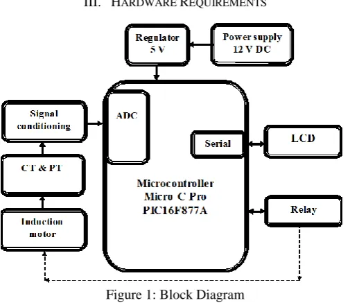
III. HARDWARE REQUIREMENTS
Figure 1: Block Diagram
The circuit consists of microcontroller along with other peripherals. We will be using microcontroller PIC16F877A. Other peripherals include Induction motor, signal conditioning circuit, current transformer, potential transformer, serial communication circuit, USB to serial converter and power supply. We will be using 1/12 HP induction motor with 3Kg-cm torques.
Signal conditioning is needed to make the current signal compatible to microcontroller to read. Current will be measured through internal ADC of microcontroller.
A. The Controller
The microcontroller used is PIC16F877A. It is an 8-bit micro-controller.
Microcontroller
PIC16F877A
Operating Voltage
5V
Input Voltage (limit)
6-20V
Digital I/O Pins
14
PWM Digital I/O
Pins
6
Analog Input Pins
6
DC Current per I/O
Pin
20 Ma
DC Current for 3.3V
Pin
50 Ma
Flash Memory
32 KB
SRAM
2 KB
EEPROM
1 KB
Clock Speed
16 MHz
Length
68.6 mm
Width
53.4 mm
Weight
25 g
Table 1: Specifications
Power:
The board can be powered via the USB connection or with an external power supply. The power source is selected automatically. External (non-USB) power can come either from an AC-to-DC adapter (wall-wart) or battery. The adapter can be connected by plugging a 2.1mm center-positive plug into the board's power jack. Leads from a battery can be inserted in the GND and Vin pin headers of the POWER connector.
The board can operate on an external supply from 6 to 20 volts. If supplied with less than 7V, however, the 5V pin may supply less than five volts and the board may become unstable. If using more than 12V, the voltage regulator may overheat and damage the board. The recommended range is 7 to 12 volts.
Memory:
The PIC16F877A has 32 KB (with 0.5 KB occupied by the boot loader). It also has 2 KB of SRAM and 1 KB of EEPROM (which can be read and written with the EEPROM library).
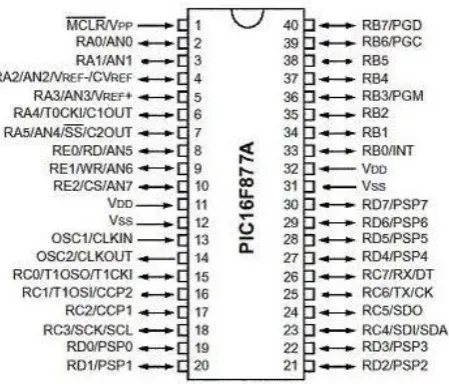
Input and Output:
Figure 2: PIC16F877A mapping
Each of the 14 digital pins can be used as an input or output, using pinMode(), digitalWrite(), and digitalRead() functions. They operate at 5 volts. Each pin can provide or receive 20 mA as recommended operating condition and has an internal pull-up resistor (disconnected by default) of 20-50k ohm. A maximum of 40mA is the value that must not be exceeded on any I/O pin to avoid permanent damage to the microcontroller.
In addition, some pins have specialized functions:
Serial: 0 (RX) and 1 (TX). Used to receive (RX) and transmit (TX) TTL serial data. These pins are connected to the corresponding pins of the ATmega8U2 USB-to-TTL Serial chip.
External Interrupts: 2 and 3. These pins can be configured to trigger an interrupt on a low value, a rising or falling edge, or a change in value. See the attachInterrupt() function for details.
PWM: 3, 5, 6, 9, 10, and 11. Provide 8-bit PWM output with the analogWrite() function.
SPI: 10 (SS), 11 (MOSI), 12 (MISO), 13 (SCK). These pins support SPI communication using the SPI library.
LED: 13. There is a built-in LED driven by digital pin 13. When the pin is HIGH value, the LED is on, when the pin is LOW, it's off.
TWI: A4 or SDA pin and A5 or SCL pin. Support TWI communication using the Wire library.
The controller has 6 analog inputs, labeled A0 through A5, each of which provide 10 bits of resolution (i.e. 1024 different values). By default they measure from ground to 5 volts, though is it possible to change the upper end of their range using the AREF pin and the analogReference() function.
There are a couple of other pins on the board:
AREF. Reference voltage for the analog inputs. Used with analogReference().
Reset. Bring this line LOW to reset the microcontroller. Typically used to add a reset button to shields which block the one on the board.
Communication:
The RX and TX LEDs on the board will flash when data is being transmitted via the USB-to-serial chip and USB connection to the computer (but not for serial communication on pins 0 and 1).
A Software Serial library allows serial communication on any of the PIC16F877A's digital pins. It also supports I2C (TWI) and SPI communication. The Micro C Pro Software (IDE) includes a Wire library to simplify use of the I2C bus; see the documentation for details. For SPI communication, use the SPI library. Automatic (Software) Reset Rather than requiring a physical press of the reset button before an upload, the PIC16F877A board is designed in a way that allows it to be reset by software running on a connected computer. One of the hardware flow control lines (DTR) of the ATmega8U2/16U2 is connected to the reset line of the PIC16F877A via a 100 nano-farad capacitor. When this line is asserted (taken low), the reset line drops long enough to reset the chip. The Micro C Pro Software (IDE) uses this capability to allow you to upload code by simply pressing the upload button in the interface toolbar. This means that the bootloader can have a shorter timeout, as the lowering of DTR can be well-coordinated with the start of the upload. This setup has other implications. When the PIC16F877A is connected to either a computer running Mac OS X or Linux, it resets each time a connection is made to it from software (via USB). For the following half-second or so, the bootloader is running on the PIC16F877A. While it is programmed to ignore malformed data (i.e. anything besides an upload of new code), it will intercept the first few bytes of data sent to the board after a connection is opened. If a sketch running on the board receives one-time configuration or other data when it first starts, make sure that the software with which it communicates waits a second after opening the connection and before sending this data. The PIC16F877A board contains a trace that can be cut to disable the auto-reset. The pads on either side of the trace can be soldered together to re-enable it. It's labeled "RESET-EN". You may also be able to disable the auto-reset by connecting a 110 ohm resistor from 5V to the reset line.
B. Regulated Power Supply
Figure 3: Regulated Power Supply Block Diagram
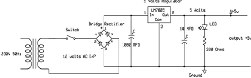
The basic circuit diagram of a regulated power supply (DC O/P) with led connected as load is shown in fig below
Figure 4: Circuit Diagram of Regulated Power Supply
The components mainly used in above figure are
230V AC MAINS
TRANSFORMER
BRIDGE RECTIFIER(DIODES)
CAPACITOR
VOLTAGE REGULATOR(IC 7805)
RESISTOR
LED(LIGHT EMITTING DIODE)
Transformers:
A transformer is a device that transfers electrical energy from one circuit to another through inductively coupled conductors without changing its frequency. A varying current in the first or primary winding creates a varying magnetic flux in the transformer's core, and thus a varying magnetic field through the secondary winding. This varying magnetic field induces a varying electromotive force (EMF) or "voltage" in the secondary winding. This effect is called mutual induction.
Bridge full wave rectifier:
The Bridge rectifier circuit is shown in fig:3.8, which converts an ac voltage to dc voltage using both half cycles of the input ac voltage. The Bridge rectifier circuit is shown in the figure. The circuit has four diodes connected to form a bridge. The ac input voltage is applied to the diagonally opposite ends of the bridge. The load resistance is connected between the other two ends of the bridge.
For the positive half cycle of the input ac voltage, diodes D1 and D3 conduct, whereas diodes D2 and D4 remain in the OFF state. The conducting diodes will be in series with the load resistance RL and hence the load current
flows through RL. For the negative half cycle of the input ac voltage, diodes D2 and D4 conduct whereas, D1
and D3 remain OFF. The conducting diodes D2 and D4 will be in series with the load resistance RL and hence
the current flows through RL in the same direction as in the previous half cycle. Thus a bi-directional wave is
converted into a unidirectional wave.A
Voltage Regulator:
A voltage regulator (also called a „regulator‟) with only three terminals appears to be a simple device, but it is in fact a very complex integrated circuit. It converts a varying input voltage into a constant „regulated‟ output voltage. Voltage Regulators are available in a variety of outputs like 5V, 6V, 9V, 12V and 15V. The LM78XX series of voltage regulators are designed for positive input. For applications requiring negative input, the LM79XX series is used. Using a pair of „voltage-divider‟ resistors can increase the output voltage of a regulator circuit.
It is not possible to obtain a voltage lower than the stated rating. You cannot use a 12V regulator to make a 5V power supply. Voltage regulators are very robust. These can withstand over-current draw due to short circuits and over-heating. In both cases, the regulator will cut off before any damage occurs. The only way to destroy a regulator is to apply reverse voltage to its input. Reverse polarity destroys the regulator almost instantly. Fig: 3.3.11 shows voltage regulator.
Figure 5: Voltage Regulator
C. LCD
LCD Background:
One of the most common devices attached to a micro controller is an LCD display. Some of the most common LCD‟s connected to the many microcontrollers are 16x2 and 20x2 displays. This means 16 characters per line by 2 lines and 20 characters per line by 2 lines, respectively.
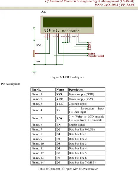
Figure 6: LCD Pin diagram
Pin description:
Table 2: Character LCD pins with Microcontroller
The LCD requires 3 control lines as well as either 4 or 8 I/O lines for the data bus. The user may select whether the LCD is to operate with a 4-bit data bus or an 8-bit data bus. If a 4-bit data bus is used the LCD will require a total of 7 data lines (3 control lines plus the 4 lines for the data bus). If an 8-bit data bus is used the LCD will require a total of 11 data lines (3 control lines plus the 8 lines for the data bus).The three control lines are referred to as EN, RS, and RW.
Pin No. Name Description
Pin no. 1 VSS Power supply (GND) Pin no. 2 VCC Power supply (+5V) Pin no. 3 VEE Contrast adjust
Pin no. 4 RS 0 = Instruction input
1 = Data input
Pin no. 5 R/W 0 = Write to LCD module
1 = Read from LCD module Pin no. 6 EN Enable signal
The EN line is called "Enable." This control line is used to tell the LCD that we are sending it data. To send data to the LCD, our program should make sure this line is low (0) and then set the other two control lines and/or put data on the data bus. When the other lines are completely ready, bring EN high (1) and wait for the minimum amount of time required by the LCD datasheet (this varies from LCD to LCD), and end by bringing it low (0) again.
The RS line is the "Register Select" line. When RS is low (0), the data is to be treated as a command or special instruction (such as clear screen, position cursor, etc.). When RS is high (1), the data being sent is text data which should be displayed on the screen. For example, to display the letter "T" on the screen we would set RS high.
The RW line is the "Read/Write" control line. When RW is low (0), the information on the data bus is being written to the LCD. When RW is high (1), the program is effectively querying (or reading) the LCD. Only one instruction ("Get LCD status") is a read command. All others are write commands--so RW will almost always be low.
Finally, the data bus consists of 4 or 8 lines (depending on the mode of operation selected by the user). In the case of an 8-bit data bus, the lines are referred to as DB0, DB1, DB2, DB3, DB4, DB5, DB6, and DB7.
D. Current transformer & Potential transformer
Current transformers and potential transformers are used for current &voltage measurements respectively.
IV.
S
OFTWARER
EQUIREMENTS Micro C pro compiler:The open-source Micro C Pro Software (IDE) makes it easy to write code and upload it to the board. It runs on Windows, Mac OS X, and Linux. The code is written in Micro C Pro Software and is fed to microcontroller.
The environment is written in Java and based on Processing and other open-source software. This software can be used with any PIC board.
Algorithm:
1. Initialize system.
2. The amount of current will be converted into voltage through burden resistance by current transformer. 3. The signal shifted from non-inverting comparator send to MATLAB through controller for processing. 4. The depending upon amount of voltage voltages fault will be detected.
5. If voltage is greater than 250v then over voltage fault will be detected and load will be turn off 6. If voltage is smaller than 180v then under voltage fault will be detected and load will be turn off. 7. The depend upon current value current fault will be detected.
8. If current is greater than 1.3A current fault will be detected and load will be fault. 9. The line to ground short fault will be detected when dc voltage will be grounded.
R
EFERENCES[1]. Priyanka Nath, Jamini Das, Abdur Rohman, “A Fuzzy Logic Based Overcurrent Protection System For Induction Motor”, International Conference on Communication and Signal Processing, April 6-8, 2016. [2]. Naveena G J, Murugesh Dodakundi, “Fault Diagnosis of VSI fed Induction Motor Drive Using Fuzzy
Logic Approach” International Conference on Power and Advanced Control Engineering, 2015. [3]. Arfat Siddique, “Applications of Artificial Intelligence Techniques for Induction Machine Stator fault
diagnosis” Symposium on Diagnostic of Electric Machines, Aug. 2003.