ISSN: 2372-4811 (Print), 2372-482X (Online) Copyright © The Author(s). 2014. All Rights Reserved. Published by American Research Institute for Policy Development
Effect of Ionized Plasma Medium on Radiation Properties of
Rectangular Microstrip Antenna Printed on Ferrite Substrate
Ayman Al sawalha1
Abstract
This paper presents theoretical investigations on the radiation of rectangular microstrip antenna printed on a magnetized ferrite substrate
0.62 0.02 1.948 4
Ni
Co
Fe
O
in the presence of ionized plasma medium. The theoretical study on rectangular microstrip antenna in free space is carried out by applying the transmission line model combining with potential function techniques while hydrodynamic theory is used for it is analysis in plasma medium. By taking the biased and unbiased ferrite cases , far field radiation patterns in free space and plasma medium are obtained which in turn are applied in computing radiated power ,directivity, quality factor and bandwidth of antenna .It is found that the presence of plasma medium affects the performance of rectangular microstrip antenna structure significantly.Keywords: Microstrip Antenna, Ferrite, Plasma
1 - Introduction
Demand for compact radiators with sufficiently high gain is rapidly increasing in many application areas, as modern wireless telecommunication systems and space communications require compact antennas with high gain, which become even more relevant requirements when the radiating elements have to be combined in large antenna arrays for satellites, space vehicles, airplanes, and so on.
Microstrip patch antennas, due to their inherent capabilities (mainly low cost, low weight and low profile) are widely used in those setups [1], [2].
Even though such antennas are very thin compared to the operating
wavelength (0.05-0.01 λ) in their cross section, however, still their transverse
dimensions cannot be made arbitrarily short, since a regular patch antenna resonates at a given frequency when its linear transverse dimension is of the order of half wavelength.
An antenna mounted on a space vehicle interacts with high-density warm and non-drifting ionized plasma medium during its re-entry into the Earth's atmosphere. This high density plasma medium affects the radiation performance of the antenna significantly .In the present paper, effect of this plasma medium on the radiation properties of rectangular microstrip antenna designed on a typical ferrite substrate
0.62 0.02 1.948 4
Ni
Co
Fe
O
in the case of biased ferrite and unbiased ferrite where in thecase of biased ferrite the DC magnetic biased field is taken normal to the direction of propagation of electromagnetic waves, are investigated theoretically . Transmission line model combining with potential function techniques is used to obtain radiation properties of rectangular microstrip antenna in free space while hydrodynamic theory is used to obtain its radiation properties in plasma medium. It has been established that, for a biased ferrite slab, a normal incident plane wave may excite two type of waves (i.e. the ordinary and extraordinary wave).In the case of a normal incident wave, the ordinary wave is the same as the plane wave in a dielectric slab transversely to the biasing direction. On the other hand ,the extraordinary wave is a TE mode
polarized parallel to the biasing direction with its phase propagation constant
K
e.Thephase propagation constants
K
eandK
oof an extraordinary and an ordinary wave,respectively, may be given as follows [2,3].
2
(1)
e reff reff
f K
c
2
(2)
o reff
f K
c
2 2
(3)
r r
reff
r
0
2 2
0
1 m (4)
2 2
[
m]
(5)
r o
o
(
)
(6)
o o
H
o
(
)
(7)
m o
M
s
Where
H
ois the biased field,4
M
sis the saturation magnetisation,
is thegyromagnetic ratio as
2.8
MHz Oe
/
.In the case of extraordinary mode, the propagation constant dependence on basic parameters is give as:
2 2
2
2
(
)
(
)
(8)
(
)
e o m
o o o m
K
K
It is seen that, when
effis negative, the extraordinary wave is decaying evenif the material is lossless. The frequency range for negative
eff is
(
)
12(
)
(9)
o o m o m
The frequency limit define the approximation range within and around which the ferrites exhibit interesting microwave characteristics .The use of a biased field to control the properties of the extraordinary wave results in an externally switchable antenna .The antenna is 'of ' when an attenuating extraordinary wave in the ferrite
propagates and there is a little radiation and is 'on' when
effis positive and theordinary wave is propagating.
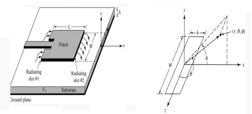
2 - Theoretical Considerations
The geometry and coordinate system of rectangular microstrip antenna are
Fig. (1): The Geometry and Coordinate System of Rectangular Microstrip Antenna
The total field in isotropic warm plasma can be decomposed in two modes, namely, transverse electromagnetic mode (EM mode) and longitudinal electroacoustic mode (plasma mode). Physically the separation of fields into two modes means that the electromagnetic and plasma wave excited by the radiating source are uncoupled .It is pertinent to mention here that electrons are assumed to be the only effective component of plasma to respond to the time varying fields. The collisions of the electrons with neutral particles, the effect of sheath formation around the antenna and the presence of external magnetic field are disregarded. For the validity of these assumptions, linearized hydrodynamic theory of plasma have been used [4].Following it ,the far-zone field expressions for a rectangular microstrip patch antenna are obtained as [5]
a - In electromagnetic mode
sin sin
sin cos( sin sin )[ ] (10)
2
e j r
o o
e
j AE hW L x z
E e
r x z
( 2) sin cos
e
x h
( 2) cos
e
z W
2
e o
o
A A
2 2
1 21 p
A
0
E
b - In Plasma mode
2
2
60(1 )
cos( sin sin )[ ] (11)
2
p j r
o p
p p
E c
A L
E X e
A r
sin( ( 2) sin cos ) sin( ( 2) cos )( 2) sin cos ( 2) cos
p p
p p
h W
X hW
h W
where
p o
o c
A
In the above expression
e and
p are the propagation constant inelectromagnetic mode and in plasma mode respectively .
The values of
E
andE
p are computed numerically and plotted inFig.2:
E
for Unbiased and Biased Ferrite for two different values of AFig.3:
E
p for Unbiased and Biased Ferrite for two different Values of A3 - Radiation Conductance
By integrating the Poynting vector over a large sphere, the expression for radiation conductance of the rectangular patch antenna in electromagnetic mode and plasma mode are give as:
E - Plane (Unbiased)
-30 -25 -20 -15 -10 -5 0 -30 -25 -20 -15 -10 -5 0 0 30 60 90 120 150 180 210 240 270 300 330 A=0.2 A=1.0
E - Plane (Biased)
-30 -25 -20 -15 -10 -5 0 -30 -25 -20 -15 -10 -5 0 0 30 60 90 120 150 180 210 240 270 300 330 A=0.2 A=1.0 Biased Case Theta(degree)
50 52 54 56 58 60
|E p | (d B ) -40 -30 -20 -10 0 A=0.2 A=0.9 Unbiased Case Theta(degree)
50 52 54 56 58 60
a - In electromagnetic mode
2
2
ee
P
G
V
Where
P
e the radiated power by the antenna is in electromagnetic mode,V
isthe edge voltage and given as
V
hE
0 andG
eis the radiation conductance and isgiven by:
3 2 2
2
2 2 2
3 2
2 2
0 0
sin sin
sin cos ( sin sin ) (12)
2 o
e
o
e A W
G
Z
L x z
d d
x z
The value of
P
e is calculated for different values of plasma to sourcefrequencies in case of biased and unbiased ferrite and plotted in figure (4).
plasma to source frequency
0.0 0.2 0.4 0.6 0.8 1.0
P
e
1e+6 1e+7 1e+8 1e+9
Pe (unbiase) Pe(biased)
b - In plasma mode
2
2
pp
P
G
V
Where
P
p the radiated power by the antenna in plasma mode is,G
pis theradiation conductance and is given by:
2 2 2
2 2
3 2
2 2
0 0
(60)
(1 )
sin sin
cos( sin sin ) sin (13)
2
p p
o
p
W c
A G
A Z
L X Z
d d
X Z
The value of
P
p is calculated for different values of plasma to sourcefrequencies in case of biased and unbiased ferrite and plotted in figure (5)
Plasma to source freqency
0.0 0.2 0.4 0.6 0.8 1.0
P
p
1e-5 1e-4 1e-3 1e-2 1e-1
Pp (Unbiased) Pp (Biased)
4 - Directive Gain
The directive gain of an antenna in a given direction is defined as the ratio of
the maximum radiation intensity
F
max .( , )
in that direction to the average radiatedpower in electromagnetic mode and given by:
max ,
4 (14)
e
e F D
P
2
2max
max
, , , (15)
F E E
The value of directivity is calculated for different values of
21
pA
in case of biased and unbiased ferrite and plotted in figure (6).Plasma Parameter (A)
0.2 0.4 0.6 0.8 1.0
D
ire
c
ti
v
it
y
0.0001 0.001 0.01 0.1
Unbiased Biased
5 – Efficiency
Efficiency
of an antenna can be calculated as [6]:100%
(16)
e
e P
P
P
P
From equations (12) and (13) the efficiency of an antenna can be calculated
.The value of
is calculated and plotted for different values of
2
1
pA
in case of biased and unbiased ferrite as shown in figure (7).
A
0.2 0.4 0.6 0.8 1.0
E
ff
ic
ie
n
c
y
(%
)
0 20 40 60 80 100
Biased Unbiased
Fig.7 :
for different Values of
21
pA
in case of Biased and Unbiased Ferrite6 – Bandwidth
The bandwidth (BW) of an antenna is calculated as [5]:
2 1
.
(17)
rrad
BW
Q
Where
Q
rad.is the total quality radiation factor and is given as:.
.
(18)
Trad
rad
U
Q
P
T
U
, is the total stored energy given by:2 .
max .
(19)
4
o eff T
V
U
E
dV
The value of
Q
rad. is calculated by using the equations (18) and (19) fordifferent values of
A
1
p
2 in case of biased and unbiased ferrite asshown in figure (8).
Plasma Parameter (A)
0.2 0.4 0.6 0.8 1.0
Q
u
a
li
ty
Fa
c
to
r
1e+1 1e+2 1e+3 1e+4 1e+5 1e+6
Unbiased Biased
Bandwidth of an antenna is calculated from equation (18) and plotted in figure (9) as shown:
Plasma Parameter (A)
0.2 0.4 0.6 0.8 1.0
B
W
%
0.001 0.01 0.1 1 10 100
Unbiased Biased
Fig.9: BW for different Values of
21
pA
in case of Biased and Unbiased Ferrite6 - Discussion and Conclusion
In this paper we have developed a concept of switchable antenna and it has
been analysed at
1
GHz
of microwave frequency range by taking rectangular patchmicrostrip antenna geometry. The parameters used for the study on biased ferrite
substrate are
4
M
s
3000
G
and biased fieldH
0
1000
Oe
while, for unbiasedIt is evident from the equation (9) that, there is a frequency range bounded by
limits, namely cut-off limit and resonance limit. In this region where
eff. is negative,the extraordinary wave is highly attenuating and therefore the antenna is effectively off as radiator.
Some salient features of rectangular geometry are summarized as follows:
1- On biasing ferrite the radiation pattern become directive in nature and the number
of lobes are found to be greater than that of the unbiased case for
A
0.2
i.e. inplasma medium.
2- The size of the patch is considerably reduced when designed on ferrite substrate.
This reduction would certainly have a wide use in creating miniaturisation of an antenna system, which has a potential application in space and cellular communication.
References
C.A. Balanis, “Antenna Theory: Analysis and Design,” 2nd ed., John Wiley &Sons, New York, 1997.
Bachyansk M.P.,"Plasma physics AnElementry Review",Proc.IRE,vol.49,1961.
Freeston I.L., "Measurments of ion density in a plasma torch using aplane probe",Electron Lett.,vol.6,No.25,1970.
Wait J.R.,"Radiation from sources immersed in compressible plasma media", Can.J.Physics,vol.42,1964.
Post, R.E.,and D.T.Stephenson,"The design of microstrip antenna array for a UHF space telemetry link",IEEE trans., Vol. AP-29,pp.129-133,1981.