Available Online at www.ijpret.com 34
INTERNATIONAL JOURNAL OF PURE AND
APPLIED RESEARCH IN ENGINEERING AND
TECHNOLOGY
A PATH FOR HORIZING YOUR INNOVATIVE WORK
A THEORETICAL STUDY OF TRIPLE QUANTUM WELL STRUCTURES UNDER
EXTERNAL FIELDS
SHRAWAN KUMAR1, L. K. MISHRA2
1. Department of Physics, G. L. A. College, Daltanganj, Nilamber Pitamber University, Medininagar, Palamu-822102 (Jharkhand).
2. Department of Physics, Magadh University, Bodh-Gaya-824234 (Bihar).
Accepted Date: 06/01/2015; Published Date: 01/02/2015
\
Abstract: Using theoretical formalism of A. Large etal [Semicond. Sci. Technol. 2002], we have studied the shallow donor impurity in triple quantum well structures. We have used the effective mass approximation in the analysis of impurity related optical spectra. Our theoretically evaluated results for intra-donor transition energy and intra-donor magneto-absorption coefficients (arb. U) are in good agreement with the experimental data and also with other theoretical workers.
Keywords: Shallow donor impurity, triple quantum well structure, Intra-donor transition energy, Intra-donor magneto absorption coefficients, coupled homogeneous linear equations, geometrical and induced field confinement, Quantum dots and super lattices, photon polarization vector, Quantum Well confined Stark effects, Large Stark Shifts
Corresponding Author: MR. SHRAWAN KUMAR
Access Online On:
www.ijpret.com
How to Cite This Article:
Shrawan Kumar, IJPRET, 2015; Volume 3 (6): 34-49
Available Online at www.ijpret.com 35
INTRODUCTION
Due to large variety of technological applications, single and multiple semiconductors quantum well structures have been extensively studied. Studies have been made in different situations including external perturbations, such as magnetic and electric fields and distinct doping processes. Nowadays, semiconducting devices are designed based on photo detector properties and magneto-optical properties of quantum- well systems. This includes the design of optical modulators based on the quantum-well confined Stark effects. There is some devices made by double-barrier and double-well systems. In this advancement, one has Triple quantum well (TQW) heterostructures. This has shown to provide interesting change in many physical properties. In particular, these TQW systems have been proven to be superior in resonant tunneling properties, as compared to double quantum wells. Apart from this, asymmetric TQW systems have been found to exhibit nonlinear behavior in the electronic transmission. This is essentially due to the internal electric field induced by photo-excited electrons and holes within the heterostructures1,2 .There is also possibilities of having different kinds of electromagnetic emission emerging from asymmetric TQW heterostructures. Another interesting application is the fabrication of a three-colour infrared photodetector which operates at a fixed bias composed of TQW structure3. Large Stark Shifts have been observed in strongly coupled (Ga,Al) As-GaAs systems4. This has been designed for modulator applications at 810nm. The rate at which the excitonic transitions change in energy with the applied electric field is a relevant parameter for the device performance.
Available Online at www.ijpret.com 36
MATERIALS AND METHODS
The effective mass Hamiltonian of a donor impurity in TQW structure, in the presence of magnetic field B=Bz and electric field F=Fz is written as
2 2 0 * 0 1 ( ) ( )
2 conf i
e e
H p A V z e Fz
m c r r
(1)
In which m* is the electronic effective mass, A0 is the vector potential which is taken in the
symmetric gauge, ε0 is the GaAs dielectric function. The TQW structures are modeled by the potential Vconf (z) and impurity is located at ri=ziz.
The eigen value problem for the given Hamiltonian is solved by adopting a particular variational scheme14. In this variational scheme both the ground state and excited states can be simultaneously obtained. The envelope wave functions are expanded in terms of the z-dependent quantum-well eigen functions fn(z) and a set of Gaussian function with fixed length parameter λj
2
, ,
( , , ) n j m im ( )
n j m j m n
z D e e f z
(2)
In which m denotes the quantum number associated with the z-component of the orbital angular momentum operator. The set of parameters covers the physical range of relevant radii associated with the potential confinement15,16. The impurity energies are obtained by solving a set of coupled homogeneous linear equations for the coefficients of the expansion Dj,mn. In the limit of Zero magnetic field, the on centre donor spectrum shows the well-known hydrogen like feature of confined impurity in quantum well. For increasing fields, the spectrum clearly exhibits the Zeeman splitting of the m=±1, ±2….excited states. In the high magnetic field regime (for Landau radii smaller than the effective Bohr radius) the energy spectrum resembles a set of Landau-like levels associated with each one of the quantum-well states in the absence of the impurity potential. The intra-donor absorption coefficient is calculated by using Fermi rule. Both circular and linear configurations are derived within the dipolar approximation in which the oscillator strength of the transition is
2 '
0 ( fm .(p e A ) im)
c
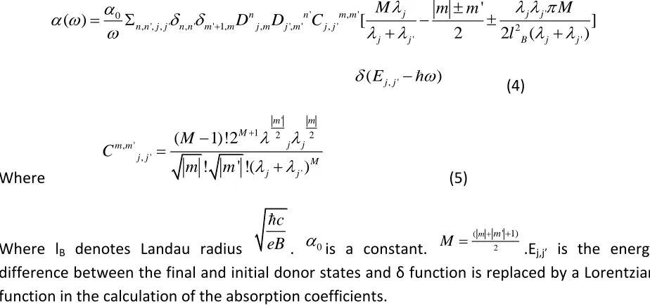
Available Online at www.ijpret.com 37 Here, ε denotes the photon polarization vector. For linear photon radiation, the only allowed transitions are those between impurity states with the same angular momentum quantum numbers (m=m’) and for quantum well states with n-n’ being equal to an odd numbers.
For the case of in-plane circular photon polarization configuration, one obtains
'
' , '
0
, ', , ' , ' ' 1, , ', ' , ' 2
' '
'
( ) [ ]
2 2 ( )
j j j
n n m m
n n j j n n m m j m j m j j
j j B j j
M m m M
D D C
l , ' (Ej j )
(4)
Where
'
1 2 2
, ' , ' ' ( 1)!2 ! ' !( ) m m M j j m m
j j M
j j M C m m (5)
Where lB denotes Landau radius
c
eB . 0is a constant. (
2 ' 1)
m m
M
.Ej,j’ is the energy difference between the final and initial donor states and δ function is replaced by a Lorentzian function in the calculation of the absorption coefficients.
RESULTS AND DISCUSSION
Available Online at www.ijpret.com 38 radiation for central-well impurity position. The intra-donor absorption coefficient is calculated by using the Fermi rule. Both circular and linear coefficients are determined with the dipolar approximations in which the oscillator strength of the transition is proportional to
2 '
0
.( )
m m
f i
e
p A
c
Available Online at www.ijpret.com 39 results are in god agreement with the experimental data19. There are some recent20-30 results which also reveal the same findings.
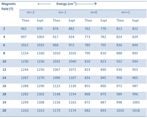
Table T1
An evaluated result of energy of TQW1 structure as a function of the magnetic field for different values of z-component angular momentum m. Results were compared with the
experimental data18.
Magnetic field (T)
<--- Energy (cm-1)---
m=-2 m=-1 m=0 m=+1
Theo Expt Theo Expt Theo Expt Theo Expt
2 962 970 874 882 762 770 812 822
4 997 1002 917 924 773 782 824 829
6 1022 1025 968 972 789 795 836 844
8 1154 1160 1010 1016 799 810 888 893
10 1230 1236 1032 1040 810 823 922 934
12 1244 1250 1067 1072 823 840 939 953
14 1267 1270 1096 1107 834 845 956 965
16 1288 1290 1122 1130 855 860 972 987
18 1292 1302 1148 1154 868 875 989 996
19 1299 1308 1156 1163 872 887 998 1005
Available Online at www.ijpret.com 40
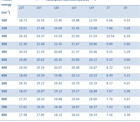
Table T2
An evaluated result of intra-donor magneto-absorption coefficients as a function of photon energy (cm-1) at fixed magnetic field for TQW1 structure for linear polarization radiation for
central-well impurity position
Photon energy
(cm-1)
<--- Absorption coefficient(arb.U)----
22T 20T 18T 16T 14T 2T 0T
100 18.72 16.52 15.40 14.88 12.59 6.66 4.52
150 19.61 17.48 16.68 15.45 13.68 7.86 5.68
200 26.32 24.37 23.59 22.50 21.54 10.54 6.59
250 21.30 22.48 21.45 21.87 20.86 0.89 5.86
300 20.54 21.59 20.89 21.37 20.48 9.55 5.29
350 19.86 20.62 20.35 20.89 20.12 9.22 4.86
400 19.50 20.19 20.07 20.48 19.87 8.72 4.53
450 18.89 19.59 19.86 20.13 19.53 8.49 4.22
500 18.35 19.17 19.43 19.79 19.19 8.17 4.07
550 18.07 18.87 19.12 19.27 18.88 7.97 3.98
600 17.97 18.33 18.88 19.04 18.69 7.76 3.67
700 17.62 18.05 18.40 18.87 18.37 7.43 3.42
Available Online at www.ijpret.com 41
TableT3
An evaluated results for intra-donor transition energies as a function of magnetic field for central-well and lateral-well impurity position for TQW1 (100mev) results were compared
with experimental data18
Magnetic field (T)
--- Transition energy (cm-1)----
Central-well impurity position Lateral-well impurity position
Theo. Expt Theo. Expt.
2 60.6 58.2 48.5 50.9
4 82.5 80.6 55.6 61.8
6 140.2 137.3 84.5 89.5
8 155.6 151.9 110.8 115.2
10 168.8 160.6 127.2 130.8
12 178.2 172.6 138.5 142.6
14 198.6 190.8 150.6 155.9
15 222.5 220.3 168.7 172.6
16 246.8 241.7 172.8 180.4
17 252.5 250.4 187.5 192.3
18 267.8 262.7 200.6 210.4
Available Online at www.ijpret.com 42
Table T4
An evaluated result for intra-donor transition energies as a function of magnetic field for central-well impurity position and lateral-well impurity position for TQW2 (50mev) structure.
Results were compared with the experimental data18
Magnetic field (T)
<--- -Transition energy (cm-1)----
Central-well impurity Position Lateral-well impurity position
Theo. Expt. Theo. Expt.
2 10.2 9.8 20.6 22.8
4 25.6 22.6 52.8 55.3
5 39.2 42.2 69.2 72.6
6 56.8 57.9 88.8 90.8
8 112.6 115.6 120.9 124.3
10 132.9 135.9 140.2 142.2
12 150.6 155.4 162.4 170.6
14 167.5 168.3 188.9 190.8
15 175.4 178.6 200.4 205.5
16 182.3 184.2 205.8 209.8
17 188.9 190.4 210.7 212.6
18 200.8 202.6 232.4 240.3
Available Online at www.ijpret.com 43
Table T5
An evaluated result of absorption coefficient (arb.U) of TQW1 (100mev) structure as a function of photon energy (cm-1) for lateral-well impurity position and central-well impurity
position for fixed magnetic field B=5T and different electric field intensities
Photon energy
(cm-1)
Absorption coefficient)(arb.u)
Lateral well impurity position
Central-well impurity position
35kv/cm 30kv/cm 20kv/cm 10kv/cm 35kv/cm 30kv/cm 20kv/cm 10kv/cm
40 7.47 6.98 5.87 4.89 6.21 5.33 4.86 4.0
50 7.85 7.29 6.29 5.56 7.38 6.31 5.27 4.6
60 8.32 7.86 7.46 6.42 8.47 7.86 6.84 5.7
70 9.16 8.12 8.88 7.82 9.32 8.43 7.35 6.2
80 14.59 10.57 11.29 10.58 10.46 9.26 8.52 7.8
90 12.32 12.29 10.58 9.29 11.29 10.48 9.76 8.9
100 10.87 11.07 9.86 8.78 10.45 9.22 8.48 7.5
110 9.48 10.58 8.42 8.32 9.39 8.27 7.26 6.8
120 8.40 9.27 8.10 7.72 8.12 7.86 6.86 6.5
130 7.89 8.36 7.38 7.43 7.76 6.95 6.42 6.1
140 7.56 7.43 6.86 6.46 6.39 6.29 6.50 5.8
Available Online at www.ijpret.com 44
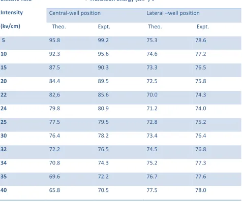
Table T6
An evaluated results of transition energy (cm-1) as a function of electric field intensity (kv/cm) for central-well and lateral well impurity position for TQW1 (100mev) structure Results were
compared with the experimental data19.
Electric field
Intensity
(kv/cm)
< Transition energy (cm-1)
Central-well position Lateral –well position
Theo. Expt. Theo. Expt.
5 95.8 99.2 75.3 78.6
10 92.3 95.6 74.6 77.2
15 87.5 90.3 73.3 76.5
20 84.4 89.5 72.5 75.8
22 82,6 85.6 70.0 74.3
24 79.8 80.9 71.2 74.0
25 77.5 79.5 72.8 75.2
30 76.4 78.2 73.4 76.4
32 72.2 76.5 74.5 76.8
34 70.8 74.3 75.2 77.3
35 69.6 72.2 76.7 77.6
Available Online at www.ijpret.com 45
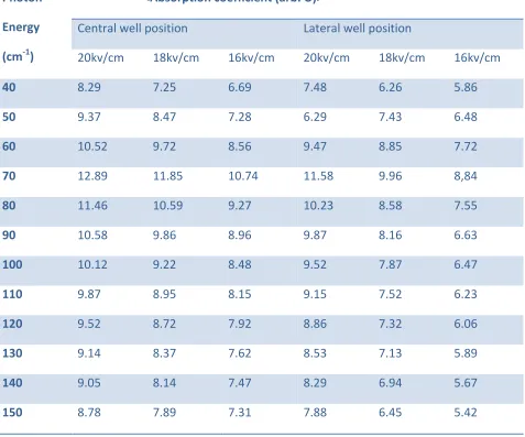
Table T7
An evaluated results of absorption coefficient (abr.u) of TQW2(50mev) structure as a function of photon energy (cm-1) for central well and lateral well impurity position for fixed magnetic
field and different electric field intensities.
Photon
Energy
(cm-1)
<Absorption coefficient (arb. U)>
Central well position Lateral well position
20kv/cm 18kv/cm 16kv/cm 20kv/cm 18kv/cm 16kv/cm
40 8.29 7.25 6.69 7.48 6.26 5.86
50 9.37 8.47 7.28 6.29 7.43 6.48
60 10.52 9.72 8.56 9.47 8.85 7.72
70 12.89 11.85 10.74 11.58 9.96 8,84
80 11.46 10.59 9.27 10.23 8.58 7.55
90 10.58 9.86 8.96 9.87 8.16 6.63
100 10.12 9.22 8.48 9.52 7.87 6.47
110 9.87 8.95 8.15 9.15 7.52 6.23
120 9.52 8.72 7.92 8.86 7.32 6.06
130 9.14 8.37 7.62 8.53 7.13 5.89
140 9.05 8.14 7.47 8.29 6.94 5.67
150 8.78 7.89 7.31 7.88 6.45 5.42
Available Online at www.ijpret.com 46
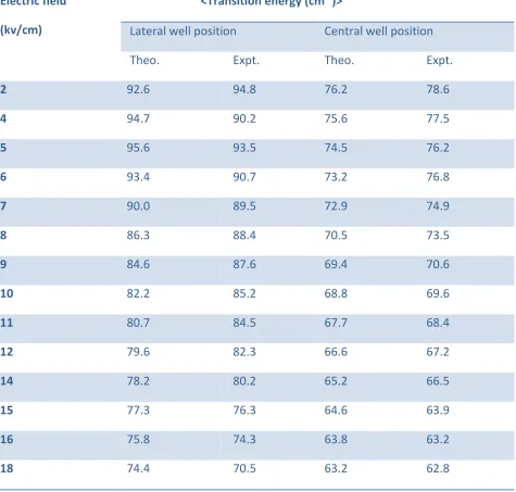
Table T8
An evaluated results of transition energy (cm-1) as a function of electric field intensities (kv/cm) for central well and lateral well impurity position forTQW2 (50mev) structure Results
were compared with the experimental data19.
Electric field
(kv/cm)
<Transition energy (cm-1)>
Lateral well position Central well position
Theo. Expt. Theo. Expt.
2 92.6 94.8 76.2 78.6
4 94.7 90.2 75.6 77.5
5 95.6 93.5 74.5 76.2
6 93.4 90.7 73.2 76.8
7 90.0 89.5 72.9 74.9
8 86.3 88.4 70.5 73.5
9 84.6 87.6 69.4 70.6
10 82.2 85.2 68.8 69.6
11 80.7 84.5 67.7 68.4
12 79.6 82.3 66.6 67.2
14 78.2 80.2 65.2 66.5
15 77.3 76.3 64.6 63.9
16 75.8 74.3 63.8 63.2
Available Online at www.ijpret.com 47
CONCLUSION
From above theoretical analysis and evaluation, we came across the following conclusions.
(i) In this evaluation, other intra-donor transitions allowed by the quantum angular momentum selection rules of simple quantum well systems are not visible in the intra-donor magneto-absorption coefficients due to quite small values of the calculated oscillator strength.
(ii) In this evaluation, impurity related optical absorption for TQW2 structure exhibit a different dependence on the electric field for low intensities. The results indicate the importance of the electronic confining regime which depends on the geometrical characterization of the multi-well systems, intensity of the applied fields and also the doping profile.
(iii) We have used effective-mass approximation in the analysis of impurity related optical spectra. We have obtained the results for an isolated impurity but this can be extended for a low concentration of weakly interacting impurities.
REFERENCES
1. H. S. Ahn and N. Sawaki, Solid State electron 44, 1209(2000)
2. A. Hernandez-Cabrera and A. Ramos, J. Appl. Phys. 80, 1547(1996)
3. D. Huang and M. O. Manasreh, J. Appl. Phys. 80, 6045(1996)
4. M. S. Tobin and J. D. Bruno, J. Appl. Phys. 89, 1885 (2001)
5. G. Bastard, Phys. Rev B24, 4714(1981)
6. F. J. Ribeiro and A. Large, Phys. Rev. B50, 4913(1994)
7. L. E. Oliveria, N. Porvas-Montengero and A. Large, Phys. Rev B47,13864(1993)
8. A. Bruno-Alfonso and A. Large, Phys. Rev B61, 15887(2000)
9. P. Villamil, N. Porras-Montengero and J. C. Granade, Phys. Rev B59, 1605(1999)
10. M. Pacheco, Z. Barticevic and A. Large, Physica B302, 74(2001)
11. M. Pacheco, Z. Barticevic, J. Phys: Condens. Matter 11, 1079(1999)
Available Online at www.ijpret.com 48 13. Z. Barticevic, M. Pacheco, C. Dugue and L. E. Oliveria, J. Phys: condens. Matter 14, 1021(2002)
14. Z. Barticevic, A. Large and M. Pacheco, Phys. Rev B62, 6963(2000)
15. A. Large, N. Porras-Montengero, M. de Dios-Leyva and L. E. Oliveria, Phys. Rev B53, 10160(1996)
16. F. J. Ribero, A. Large, M. Pacheco and z. Barticevic, J. Appl. Phys. 82, 270(1997)
17. A. Large, M. Pacheco and Z. Barticevic, Semicond. Sci. Technol.17, 952(2002)
18. F. J. Riberio, A. Large and A. Bruno-Alfosov, Semicond. Sci. Technol. 16, 262(2001)
19. M. S. Tobin and J. D. Bruno, J. Appl. Phys 92, 1732(2002)
20. M. S. Moon, R. Rajamal , S. Buni, D. Wong and D. H. Chow, Appl. Phys. Lett. 87, 183110(2005)
21. A. Dararei, A. Tahraoui, D. Sanvitto and A. M. Fox, Appl. Phys. Lett.88, 051113(2006)
22. M. C. Bafno, P. Sen, P. K. Sen, Ind. J. Pure& Appl. Phys. 47, 949(2007)
23. A. K. Chelcraft, S. Lam, R. Oulfow, M. S. Fox and M. Hopkinsen, Appl. Phys. Lett. 90, 241117(2007)
24. P. Bhattachrge, Su. Xioohno. G. Ariyawanso and A. G. Perra, Proceedings of IEEE 95, 1828 (2007)
25. A. G. Silva, C. A. Parra- Murillo, P. T. Moraus and M. Hopkinsen, Opt. Express.16, 19201(2008)
26. H. T. Chen, W. J. Padila, M. J. Cicle and A. Taylor, Nat: Phonotics 3, 148(2009)
27. X. G. Peralta, I. Brener, W. J. Padila , E. W. Young and J. Reneo, Matamaterials (Amsterdam) 4, 83(2010)
28. A. Gabbay, J. Reneo. J. R. Wendl, A. Gin, M. C. Wanka and I. Brener, Appl. Phys. Lett. 98, 203103(2011)
29. Y. Todorov and C. Sirtori, Phys. Rev. B85, 045304(2012)
Available Online at www.ijpret.com 49 31. T. Mishra, T. G. Sarkar and J. M. Bandyapadhya, Phys. Rev. E89, 012103 (2014)