Daniele Casagrande
STUDY OF TIMBER-FRAME BUILDING SEISMIC
BEHAVIOUR BY MEANS OF NUMERICAL MODELLING
AND FULL-SCALE SHAKE TABLE TESTING
Prof. Maurizio Piazza
UNIVERSITY OF TRENTO
Engineering of Civil and Mechanical Structural Systems - XXVI Cycle
Final Examination 10/ 04 / 2014
Board of Examiners
Prof. Maurizio Piazza (University of Trento)
ACKNOWLEDGEMENTS
I would like to thank my supervisors prof. M. Piazza and prof. R. Tomasi for giving me the possibility to work within the Timber Research Group of University of Trento and for supporting me during these three years. It was a great pleasure to collaborate with all the staff. A particular acknowledgement goes to Tiziano Sartori, Ivan Giongo, Paolo Grossi, Cristiano Loss and Simone Rossi.
A particular acknowledgement to Rubner Haus company and FederLegnoArredo federation for partially funding my PhD grant.
I am really grateful to undergraduate students for their important help: Alessandro Armanini, Gianluca Mischi, Marco Pedrotti, Simone Rossi, Federico Pederzolli, Alessandro Franciosi, Mirko Testoni and Michele Zanotelli.
The staff of Eucentre TreesLab is gratefully acknowledged for their assistance during the seismic tests.
A particular thank to technical staff of the Material and Structural testing laboratory of the Department of Civil, Environmental and Mechanical Engineering of the University of Trento: Alfredo Pojer, Tiziano Dallatorre, Ivan Brandolise and Luca Corradini.
SUMMARY
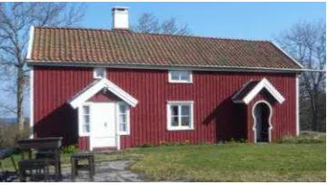
Timber frame constructive system can be considered one of the most important and most spread worldwide. In many countries, such as U.S.A., Canada, New Zealand, Germany and Scandinavia, the constructive process of timber buildings is characterized by a strong tradition and experience, so that most of low-rise residential houses are generally constructed using wood-based materials. On the contrary, in Italy the timber frame construction system do not belong to the residential building tradition. In fact, the majority of residential houses is characterized by masonry structures (typically if built before the 70’s) or by reinforced concrete ones. However, during the last decade, the timber construction system has been characterized by a significant growth in the Italian market. The increasing sensitivity to environmental issues and the need to reduce the construction time in situ, in addition to the importance of the design details, have given Italian timber buildings a leading role in the constructive market also in European Subalpine countries (historically not associated with such construction technology).
The timber-frame structural type has not been put on the Italian market referring to the North American constructive system but to the European one and in particular to the constructive system of those countries characterized by high tradition and experience in this field (Scandinavia, Germany and Austria). The European constructive system differs from the American one mainly for the considerable prefabrication process. This makes the building similar to an industrial product. Moreover, larger sizes of the elements constituting the walls themselves are used. The traditional American "plat-form frame" system is generally made up with "two by four" studs (39 by 89 mm) whereas in European countries larger cross section elements (usually 60-100 mm by 100-140 mm) are used.
One of these has been the CHI-QUADRATO industrial research project whose objective has been the study of structural, thermic and constructive matters for a typical Italian timber-frame constructive system. Within this project, the Department of Civil, Mechanical and Structural Engineering of University of Trento has been involved to investigate the seismic behaviour of such buildings. The research program has been characterized both by a wide experimental campaign and by the proposal of numerical and analytical models for the analysis and the design of timber buildings under seismic loads. Some of these topics are deeply investigated and described by the work presented in this thesis.
The work has been divided in three different but closely related phases.
In the first part, the behaviour of a single timber-frame wall under a horizontal force is discussed. The main objective is the proposal of some simplified analytical expressions aimed to describe both its linear and its non-linear behaviour. Depending on the mechanical and geometrical properties of the structural components, an analytical model for the prediction of the stiffness, strength and ductility of the wall is presented. This model may be used both for the implementation of a simplified numerical model of the wall and for the definition of the relationship between the local mechanical properties (structural members and connection devices) to the wall ones. This aspect is crucial in the traditional approach of seismic engineering and represents an innovative issue for timber buildings.
In the second part of the thesis, a linear numerical modelling for the analysis of multi-storey timber-frame buildings under seismic loads is presented. In common practice the seismic analysis models for timber buildings are very simple and based on strong hypotheses. The wall stiffness is usually considered linear dependent on the wall length and the lateral force method is often used, without taking account of the dynamic properties of the structure. However, in many cases a more advanced analysis should be performed, (i.e. modal response spectrum analysis) requiring a suitable numerical model capable to consider all significant deformation contributions of timber frame walls. In the first part of the thesis in fact, is demonstrated that the wall stiffness cannot be considered a priori linearly proportional to the wall length. For these reasons an innovative numerical modelling, based on the single wall numerical model and a new analysis approach are discussed. The analysis model is defined “unified” because it can used for different timber structural types and not only for the timber frame building, objective of this thesis.
INDEX
ACKNOWLEDGEMENTS ... 5
SUMMARY ... 7
INDEX ... 11
1 INTRODUCTION ... 17
1.1 Objectives and thesis layout ... 24
2 STRUCTURAL DESIGN OF TIMBER-FRAME WALLS ... 27
2.1 Vertical load path... 30
2.2 Out-of-plane horizontal loads ... 33
2.3 In-plane horizontal force ... 34
2.4 Seismic horizontal force distribution ... 41
2.5 Timber-frame building behavior factor q ... 43
3 LINEAR ANALYSIS OF A TIMBER-FRAME WALL UNDER A HORIZONTAL FORCE ... 47
3.1 Elastic horizontal displacement of a timber frame wall under a horizontal force .. ... 47
3.1.1 Rigid-body rotation ... 48
3.1.2 Sheathing panel shear deformation ... 49
3.1.3 Sheathing-to framing fastener deformation ... 50
3.3 Parametric study of the wall stiffness ... 60
3.4 Finite element modelling of a timber-frame wall ... 62
3.4.1 Complete model ... 62
3.4.2 Simplified model ... 63
4 ELASTO-PLASTIC ANALYSIS OF A TIMBER -FRAME WALL UNDER A HORIZONTAL FORCE ... 67
4.1 Rheological model for the assessment of the non-linear behavior of a timber-frame wall ... 68
4.2 Mechanical properties of sources of deformation ... 69
4.2.1 Rigid body rotation ... 69
4.2.2 Friction block ... 71
4.2.3 Horizontal non-linear spring for the rigid-body rotation of the wall ... 71
4.2.4 Rigid-body translation contribution ... 73
4.2.5 Sheathing-to-framing fastener contribution ... 75
4.3 Definition of the idealized elasto-plastic behavior of a timber-frame wall ... 78
4.4 Elasto-plastic behaviour of a fully anchored timber-frame wall ... 87
4.4.1 Elasto-plastic analysis of a fully anchored wall with E.A.T.W.-1.0 ... 90
4.5 Case study ... 101
4.6 Performance based seismic design of a timber-frame wall ... 108
4.6.1 Design Example ... 111
5.1 A backup numerical modelling for multi-storey walls under horizontal forces 122
5.1.1 Backup numerical modelling for a vertically-aligned wall (m x 1) ... 122
5.1.2 Study of 1-storey series of walls (1 x n) ... 124
5.1.3 Case study ... 126
5.1.4 Modelling for a series of walls (m x n) ... 130
5.1.5 Case study ... 131
5.2 Linear seismic analysis of timber frame walls ... 135
5.2.1 Lateral force method ... 135
5.2.2 Modal Response Spectrum analysis ... 136
5.2.3 Case study ... 140
6 3-STOREY TIMBER-FRAME BUILDING SHAKE TABLE TEST ... 147
6.1 Geometry and Design of the specimen ... 147
6.2 Specimen assembly and description of instrumentation ... 152
6.3 Test design ... 157
6.4 Analysis of results ... 164
6.4.1 Global hysteretic response ... 173
6.4.2 Modal testing ... 175
6.5 Analysis of results ... 183
7.2 Analytical analysis model of 1-storey timber frame wall nonlinear behaviour (b) .
... 189
7.3 Full scale 3-storey timber frame building shake table test (c) ... 190
REFERENCES ... 193
1
INTRODUCTION
Timber frame constructive system can be considered as one of the most important and most spread worldwide. In many countries, such as U.S.A., Canada, New Zealand, Germany and Scandinavia (Figure 1.1), this constructive process is characterized by a strong tradition and experience, so that most of low-rise residential houses are generally constructed using wood-based materials.
Standards and Line Guides are nowadays available. Conversely, for timber constructions, many aspects have not yet been investigated and the gap with other materials has not still been bridged. In spite of this shortcoming, a lot of construction handbooks exist, representing the cultural baggage of the timber-frame structures. Based on a strong tradition, they describe exhaustively the realization phases, the details and the materials which should be used in order to satisfy the structural and serviceability requirements.
During last 30 years there has been a significant increase of tests and research programs aimed to the technological development of new devices or wood based materials and to the improvement of timber-frame building structural performances. The significant damages from earthquakes and high wind loads has created a need to examine the current design practice. As reported in next chapters, the horizontal load design is without any doubts the most significant and relevant part of the design process for a timber frame building because it greatly influences the choice of structure elements and number of the connection devices (angle brackets, hold-down, etc.). The results of these studies and researches have permitted to get a new design philosophy which, added to the tradition and experience, has been needed to improve the timber-framed building performances, in particular under seismic loads. However, as reported above, the gap with others types of construction is still to be bridged: nowadays many research programmes have started in several countries characterized by a high seismic hazard.
The timber-frame construction system has not been put on the Italian market referring to the North American structural type but to the European one, and in particular to the constructive system of those countries characterized by high tradition and experience in this field (i.e. Scandinavia, Germany and Austria). The strict performances required by Italian Guidelines and Standards about thermal insulation, sound insulation, vibration and durability, make the European constructive system, without any doubts, the most suitable for Italy. In order to optimize the constructive process and to guarantee definite construction times in situ, the European constructive system is characterized by a considerable prefabrication process, making the building similar to an industrial product (Figure 1.2, Figure 1.3). The assembly in the factory of the framed-walls, which constitute the primary structural element, guarantee to reduce significantly the work phases in situ (joining the walls, laying the floors and making the final finishes) and thus to reduce both the constructive times and the mistakes in progress. Hence, it is clear how the whole construction process must be supported by a careful design phase in order to produce in the factory all structural elements and to make them ready for their placing in situ. A resulting increase of the production quality is expected: all details must be designed and built on purpose.
A further reason for which the European timber-frame constructive system differs from the North American one is the size of the elements constituting the walls themselves. The traditional "plat-form frame" system generally is characterized in fact the so-called "two by four" studs whereas in Italy and in European countries larger cross section elements (usually 60-100 mm by 80-160 mm section) are used. This guarantees the possibility of interposing a thicker material insulation layer in the walls. Moreover a higher robustness of the construction is obtained.
conducted on the European timber framed system, dealing with different interesting topics, but very few of them have been concerned with the performance of timber buildings under seismic loads. The main reason is that European countries with an high tradition in timber constructions cannot be considered significant seismic areas.
Figure 1.2: Timber frame wall assembling in the factory
However, it is important to highlight how the seismic behaviour of timber buildings has been deeply investigated in other countries, such as U.S.A and New Zealand, which, as known, are characterized by a very high seismic hazard. The most important international research projects have been conducted in these countries, improving significantly the seismic timber buildings behaviour knowledge. Nevertheless the North American constructive system, as mentioned previously, differs from the European one, both for the prefabrication process and for the size of the wall elements.
For this reason in the last years many research projects, aimed at the study of the timber buildings seismic behaviour, have been financed in Europe in order to propose new design rules and Standards requirements, and to develop new useful technologies and devices for timber buildings in seismic areas.
Figure 1.4: CHI-QUDRATO Research Program Layout
The research has been divided in three different, but sequential and closely related, working phases (Figure 1.4).
Figure 1.5: Hold Down Load Test
The second phase studied the behaviour of a single timber frame wall. By means of the data collected during the first phase an experimental campaign has been designed and performed in order to investigate the behaviour of a timber frame wall subjected to a horizontal force (Figure 1.6). In addition, numerical and analytical analyses have been developed for the prediction of the wall behaviour, depending on the mechanical and geometrical properties of the structural components.
Figure 1.6: Timber Frame Wall Load Test
1.1 Objectives and thesis layout
The work of this thesis focuses on the second and the third phase of the research program described in the previous section and is concerned with both the experimental campaign and the numerical analyses.
Chapter 2 reports the common structural verifications required for a timber frame wall under vertical and horizontal loads. The role of each structural component (wood members and connection devices) is described. Moreover some aspects of the common-in-practice design methods and the related assumptions are discussed.
In chapters 3 and 4 the behaviour of a single wall under a horizontal force is investigated. Several analytical expressions are proposed in order to describe the linear and the non-linear behaviour of a timber frame wall subjected to a horizontal load. Depending on the mechanical properties of each structural component, an analytical prediction model capable to evaluate the strength, stiffness and ductility of the wall is presented and a simplified numerical modelling is described. The proposed analysis method defines the analytical relationship between the local mechanical properties (strength, stiffness and ductility), related to the structural components and to the connection devices, and the wall’s ones. This matter is crucial in the traditional approach of seismic engineering and represents an innovative issue for timber building seismic design. As known, in fact, the seismic design should be referred not only to structure strength but also to its stiffness (fundamental for serviceability limit states) and to its ductility (required for the definition of the behaviour factor). Both Italian and European Standards [NTC08, Eurocode 8] are nowadays quite lacking in requirements for the seismic design of timber buildings. A direct proof is that the design rules which are to be satisfied in order to guarantee a high behaviour factor, and hence a high energy dissipation during a seismic event, are very few, as described in chapter 2. Moreover no specific rule for the application of the capacity design of a timber structure is suggested
consider all significant deformation contributions of timber framed walls. In the first part of the thesis. in fact. is demonstrated that the wall stiffness cannot be considered a priori linearly proportional to the wall length. For these reasons an innovative numerical modelling, based on the single wall numerical model, and an new analysis approach are presented.
Chapter 6 describes a full scale three-story building shaking table test at the Eucentre laboratory in Pavia (Italy). Several interesting aspects about the seismic performance of a full scale timber building, designed in accordance with Eurocode 8, were investigated. The interaction between the structural components was in particular analysed. More than one hundred instruments were used to monitor the behaviour of the building during the seismic tests measuring accelerations, displacements and forces. The main results and conclusions are reported. The design phase, the execution tests and the results are described.
2
STRUCTURAL DESIGN OF TIMBER-FRAME WALLS
Timber frame buildings are characterized mainly by a “wall” structure. Unlike “frame” structure, both vertical and horizontal loads are absorbed by timber-frame walls. Therefore, the timber-frame wall represents the fundamental structural element of the building as it transmits gravity loads to the foundations and guarantees the stability of the whole structure against lateral forces (wind or earthquake).
from2.5mm to3.1mm, orstaples. Fastener spacing ranges between 50mm and 150 mm along the beams and the outer studs of each panel. In order that the centre stud may be considered to constitute a support for a sheet, the spacing of fasteners in the centre stud should not be greater than twice the spacing of the fasteners along the edges of the sheet.
Figure 2.1: Timber-frame wall [Rossi, S. 2012]
Figure 2.2: Hold-downs
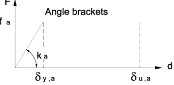
Figure 2.3: Angle brackets
Horizontal floors are generally made up by box section elements or by wooden joists. In both cases in order to achieve a diaphragm behaviour of the floor, timber panels should be superimposed. An efficient floor connection to the underlying walls is also required in order to transfer seismic loads to the structural bracing system, represented by the walls themselves.
Figure 2.4:Bottom beam Inclined screws
Figure 2.5: Hold-down and Angle brackets positioning
2.1 Vertical load path
walls can thus be neglected from a structural point of view; they play only the role of partition walls.
Timber-frame walls are characterized by the presence of a top timber beam on which are generally connected the floor elements by means of vertical screws. The top beam is supported in turn by equally spaced (60-80 cm) vertical timber studs. In case of openings (windows or doors, Figure 2.6), orthogonal wall joints or significant concentrated loads on the top beam, the insertion of additional studs or the use of larger section studs may be required. It is important to highlight that the frame wall prefabrication is particularly efficient and cost-effective if the structure is regular. In this case, in fact, an excessive insertion of additional elements (studs or lintels) is not necessary. Wall modularity represents a significant advantage in the prefabrication phase.
Figure 2.6: Openings in a prefabricated timber-framed wall
v ,d,ub fv ,d,ub
τ
≤ (2.2)where:
- σm,d,ub is the design bending stress for the upper beam
- fm,d,ub is the design bending strength for the upper beam
- τv,d,ub is the design shear stress for the upper beam
- τv,d,ub is the design shear strength for the upper beam
The section size of studs should be selected in order to satisfy the stability verification. Stud section is usually rectangular: the base section is parallel to the wall length direction and whereas the section height is equal to the wall thickness. Since in both directions studs may be assumed as a vertical pinned beam, the z-z axes (Figure 2.7) should be considered as the axis with the greater slenderness. Nevertheless the presence of a good connection between the sheathing panel and the stud guarantees a considerable reduction of the stud effective length along the z-z axis . For this reason the stud stability verification is carried only referring to the y-y axis according to the equation (2.3), as reported in section 6.3.2 of Eurocode 5:
0 0
c, ,d,stud
k
c ,y yf
c, ,d,studσ
≤
−⋅
(2.3)where:
- σc,0,d,stud is the design compressive stress along the grain
- fc,0,d,stud is the strength compressive stress along the grain
c,90,d,lb
k
c,90f
c,90,d,lbσ
≤
⋅
(2.4)Where:
- σc,90,d,bb is the design compressive stress perpendicular the grain for the bottom
beam
- fc,0,d,bb is the strength compressive stress perpendicular the grain for the bottom
beam
Figure 2.7: Timber-frame wall model loaded by uniform vertical load qv and wind out-of-plane
horizontal load qh
effect of the wind out of plane bending and of the vertical load qv compression is to be
considered. Also in this case each stud is assumed a simple pinned beam. The expression for a column subjected to combined bending and compression, according to EC5, should be satisfied:
, ,d, c,0,d,
, c,0,d, , ,d,
1
m y stud stud
c y stud m y stud
k
f
f
σ
σ
+
≤
⋅
(2.5)2.3 In-plane horizontal force
The calculation model used for the wall verifications against vertical loads assumes the studs as simple pinned vertical elements, connected superiorly and inferiorly by a continuous beam. Hence, it is evidence how the wall cannot support horizontal actions in its plane and a bracing, capable to guarantee the lateral stability of the frame, is required (Figure 2.8).
Figure 2.8: Labile frame loaded by a horizontal force F
case of wooden panels and staples in the case of gypsum-fibre panels). The panel length should be equal to twice stud spacing to guarantee a regular nailing spacing on the panel edge. The panel should also be nailed to the central stud (usually the spacing is twice the spacing required on the edge of the panel) in order to prevent the panel shear instability.
The shear transmission between the sheathing panel and the timber frame may be analysed using in first approximation the lower bound theorem limit analysis, assuming a rigid-perfectly plastic behaviour of the cylindrical fasteners and an infinite stiffness of the wooden frame and of the panel. Supposing a constant shear stress distribution on the panel edge, it is possible to calculate, by simple equilibrium, the shear stress magnitude. Considering a wall with length l equal to the length b of a single panel (the distance between the studs is therefore equal to b/2) and considering a regular fastener spacing s along the panel edge (Figure 2.9), the shear stress vd on the edge of the
panel is given by:
d d
F
v
b
=
(2.6)where Fd is the horizontal force acting on the wall. The shear force Fc,d on each fastener
is therefore equal to:
,
d
c d d
F
F
v
s
s
b
Figure 2.9: Sheathing panel shear stresses
In order to prevent the wall rigid rotation a compression force N and a force traction T are to be transferred to the foundation:
d
d d
F h
T
N
b
⋅
=
=
(2.8)where h is the height of the wall.
If the compression force can be transmitted directly to the ground by the simple contact of the stud with the foundation element, for the transmission of the vertical tensile force a specific connection device is required. This device, called hold-down, is positioned on each corner of the wall and connected to the outer studs by means of ring nails and to the foundation by means of anchor bolts.
,
d
a d a
F
F
s
b
=
⋅
(2.9)If the horizontal force F and the traction force T are to be transmitted from an upper wall to a lower one, suitable devices should be used, such as steel plates nailed to the wall (Figure 2.10).
Figure 2.10: Nailed steel plates for upper wall connection
In most cases the walls are subjected by a uniform load (dead load and live load) as described in section 2.1: the equilibrium of the wall thus should take into account its stabilizing effect (Figure 2.11). Assuming the centre of rotation of the wall is placed at one of the bottom corner of the wall, the vertical load qv is transmitted only to two outer
studs; the compressive force is equal to:
2
qq l
one. This force is to be added and subtract respectively from the tensile and compressive force of the outer studs
Figure 2.11: Timber frame wall under a horizontal force and a uniform distributed vertical load
The verifications required for a timber-frame wall loaded by a horizontal force Fd, are
reported in the following equations, according to Eurocode 5 and taking account of all possible failure mechanisms.
For the verification of the sheathing-to-framing fastener connection the design force acting on each fastener Fc,d,fastener should be lower than the fastener lateral design capacity Fc,rd:
, , ,r
d
c d fastener c d
F s c
F
F
b
⋅ ⋅
where c is equal to 1 if the length panel b is greater than h/2, 2b/h if b is within h/4 and h/2, 0 if b is less than h/4. Experimental campaigns in fact demonstrated how the shear capacity of the wall is reduced if the geometrical ratio h/b is greater than 2 and it should be neglected if greater than 4.
The outer stud tensile force produce a tensile tension σt,o,d,externalstud that should be lower than the design tensile strength along the grain ft,o,d,externalstud
,0, , ,0, ,
2
dt d externalstud t d externalstud
stud
F h
q b
b
f
A
σ
⋅
−
⋅
=
≤
(2.12)The outer stud stability is verified as in the case of the static load, taking account of the contribution of both the seismic and the static axial force:
,0, , , ,0, ,
2
dc d externalstud c y c d externalstud
stud
F h
q b
b
k
f
A
σ
⋅
+
⋅
=
≤
⋅
(2.13)Also for the bottom beam perpendicular to the grain compression the same expression of static load can be considered:
,90, , ,90 ,90,
2
d
c d bottombeam c c d eff
F
h
q b
b
k
f
A
σ
⋅
+
⋅
=
≤
⋅
(2.14)Lastly, the sheathing panel design shear τd,panel should be lower than the panel shear strength fv,d. The coefficient kc is used to consider the panel slenderness. The
verification is expressed as:
, ,
d
d panel c v d
F
k
f
b t
τ
=
≤ ⋅
the panels to the frame itself. Also in this case, in order to know the magnitude of the force effecting on each fastener it is possible to apply the lower bound theorem limit analysis. It is simple to demonstrate how the shear force vd on the edge of the panel in this case is equal to:
1
N d d
i i i
F
v
b c
=
=
⋅
∑
(2.16)where N is the number of sheathing panels whose height is greater than h/4. As for a single panel wall sheathing panels characterized by a ratio h/b greater than 2 cannot transfer efficiently the flow of shear stress. For this reason also in this case the a coefficient ci is used. where N is the number of sheathing panels whose height is greater
than h/4.
Figure 2.12: Timber frame wall with length l
, , ,r 1
1
Nc d fastener d c d
i i i
F
F s
F
b c
=
=
⋅ ⋅
∑
≤
(2.17)where ci is equal to 1 if the length panel b is greater than h/2, 2b/h if b is within h/4 and h/2, 0 if b is less than h/4
Also in this case the rotation and the translation of the wall are prevented respectively by hold-downs and angular brackets (or screws). As for a single panel wall, the tensile and compression forces on the outer studs is calculated considering the wall total length:
2
F h
q l
N
l
⋅
⋅
=
+
(2.18)2
F h
q l
T
l
⋅
⋅
=
−
(2.19)If the uniform vertical load qv is significant, the hold-down tensile force T may be negative and the analysis model is not consistent any more. The wall, in fact, does not rotate and the vertical load qv is not transferred just to the two outer stud but to all studs. In this case hold-downs would not be required because the wall overturning is prevented by the vertical load.
2.4 Seismic horizontal force distribution
The floor horizontal forces force are transmitted to the timber frame walls proportionally to their horizontal stiffness. Therefore, the seismic horizontal force Fd acting on each timber wall depends on its mechanical and geometrical properties. For this reason a correct distribution of horizontal forces would require a suitable analysis model capable of taking account of all significant deformation sources of the walls.
In the common practice, the seismic analysis of timber-frame buildings is usually carried out by means of simplified methods. In most cases, the lateral force method of analysis (as suggested by the Eurocode 8) is used and the wall stiffness is assumed directly proportional to the wall length. Hence, the analysis model can be reduced to a simple spreadsheet. This method is without any doubt very simple and intuitive but generally cannot be universally accepted.
Firstly, the lateral force method of analysis should be applied only when building dynamic response in not significantly affected by contributions from modes of vibration higher than the fundamental one (typically when the building can be assumed as regular in elevation). Otherwise a modal response spectrum analysis should be carried out, considering the contribution of all significant vibration modes. The seismic demand of the building is in fact strongly influenced by their dynamic behaviour of the structure and for this reason a static force equivalent distribution cannot be thorough.
Secondly, in the common evaluation of the wall stiffness, the deformation contribution of the connection devices is totally neglected. Nevertheless, as demonstrated by the results of the experimental campaign of the CHI-QUADRATO research project [Conte et al., 2011; Conte et al., 2010; Sartori et al., 2012, Sartori et al., 2013, Tomasi and Sartori, 2013 ], the influence of the connections is not negligible and should be adequately considered in the analysis of the structure.
to its simplicity, this model can be used to develop numerical models for a series of walls or an entire building, as reported in Chapter 5, and hence to carry out the correct distribution of horizontal seismic forces between the timber walls.
2.5 Timber-frame building behavior factor q
The seismic design of a structure is generally carried out referring to a force-based seismic design method, as reported in European Standard [EN 1998-1/A1, 2013]. The seismic action is represented by the peak inertial forces to which the structure is subjected during a seismic event. The capacity of the structure to support the seismic action is obtained from dissipating the seismic energy via its structural damaging and hence assuming a nonlinear structural behaviour. For economic reasons, in fact, because earthquake is a very intense but rare phenomenon, a damaging of the structure is accepted. However seismic linear analyses are usually carried out, dividing the elastic seismic forces by the behaviour factor q, depending on the global structural ductility. The global behaviour of a structure, and in particular its ductility strongly depends both on the mechanical properties of structural components and on the global failure mechanism. For this reason, in order to achieve high values of q, brittle failure mechanism should be prevented. Moreover, the ductility of the structural components where the energy dissipation occurs should be related to the ductility demand of the entire structure. Standards [i.e. EN 1998-1/A1, 2013; NTC08, 2008] suggest the values of q-factor for several structural types. In order to guarantee an adequate global ductility, preventing brittle failure mechanisms, some design criteria and structural details are reported for several types of buildings.
Referring to European Standards for design of structure for earthquake resistance [EN 1998-1/A1,2013] an upper limit value of the behaviour factor q equal to 5 is suggested (Figure 2.13), setting this structural type in the high ductility class (DCH).
Figure 2.14: Seismic design criteria and details for timber structures (EC8)
In order to guarantee a global high ductility of the structure, it is required that the ductility of the components where the energy dissipation occurs must be greater than 6 (Figure 2.14). The observance of this requirement, however, does not seem to be enough to guarantee completely the global structural ductility defined by the behaviour factor q. Unlike what for other material structural types (concrete or steel), no detailed suggestion about the failure mechanism that should be achieved is reported, and thus it is not clear which connection type should be selected (fasteners, hold-don or angle brackets) as the weakest element where the ductility capacity of the structure is concentrated. Moreover, very few specific structural details are suggested (Figure 2.14) and no expression about capacity design rule is reported. For these reasons current standards for seismic design of timber structures may be considered lacking if compared to other types of structures.
2001; Filiatrault and Fischer., 2001; Filiatrault et al., 2000; Folz and Filiatraul., 2002; Judd and Fonseza, 2005; Kasal et al., 1994; Kesse and Kammer, 2004; Salenicovich, 2000, Tarabia and Itani, 1997; Van de Lindt et al.,2006]. The obtained results have demonstrated good seismic performances of timber-frame wall buildings. However an analytical model capable to correlate the local ductility of connections, where energy dissipation occurs, to the global structure ductility has not proposed yet. As explained previously this relationship is crucial because defines the local ductility demand of the components in relation to the global ductility capacity.
3
LINEAR ANALYSIS OF A TIMBER-FRAME WALL UNDER A
HORIZONTAL FORCE
As reported in chapter 2, one of the most important aspect that should be investigated in order to perform a correct distribution of elastic horizontal forces in timber frame buildings is the definition of a suitable model for the elastic behaviour of walls. In this chapter an analytical expression for the calculation of the horizontal displacement of a timber frame wall under a horizontal force is proposed considering four different deformation sources. A parametric study of the wall stiffness is shown, demonstrating as a linear relationship between the stiffness and the length of the wall cannot be assumed. Moreover a simplified numerical model of the wall is proposed.
rotation, sheathing panel shear deformation, sheathing-to-framing fastener deformation, and rigid-body translation. In this section the horizontal displacement ∆ of a timber frame wall under a horizontal force is calculated. In the analysis a timber frame with length l and height h is considered. The external loads are represented by the uniform vertical load q and a horizontal force F (Figure 3.1).
Figure 3.1: Timber frame wall subjected to a horizontal force [Rossi, S.]
3.1.1 Rigid-body rotation
The source of deformation caused by the rigid-body rotation (see, Figure 3.3, I) of the wall is related to the tensile force of hold-downs, placed at each corner of the wall, for effect of the overturning moment produced by the force F. Considering also that a uniform vertical load may be acting on the wall, the hold-down vertical elongation v can be calculated as:
1
=
2
hF h
q l
v
l
k
⋅
⋅
−
⋅
(3.1)where
k
h is the hold-down stiffness.2
1
=
=
2
hv
F h
q
l
l
k
γ
⋅
−
⋅
(3.2)Thus, the horizontal displacement ∆h caused by the rigid-body rotation of the wall is:
2
=
=
2
hh
F h
q
h
h
l
k
γ
⋅
∆
⋅
−
⋅
(3.3)When the vertical load q is enough to prevent the wall rigid rotation and hence the overturning moment is lower than the stabilizing moment due to the vertical load, the hold-down elongation v must be assumed equal to zero. Consequently, Eq. (3.3) is rewritten as: 2 2
0
2
=
(
)
>
2
2
q h q hq l
when
F
F
h
h
F h
q l
q l
when
F
F
l k
l
h
⋅
≤
=
⋅
∆
⋅
⋅
⋅
⋅
−
=
⋅
⋅
(3.4)3.1.2 Sheathing panel shear deformation
The horizontal displacement ∆p (see, Figure 3.3, II) caused by the sheathing panel shear deformation contribution can be calculated deferring to the shear deformation
ζ
. This results equal to:=
=
=
(
)
p p p p bs
dx
F
F
dy
G
A
G
t
l n
ζ
χ
⋅
χ
⋅
•
G
p is the shear modulus of the sheathing panel;•
t
p is the sheathing panel thickness.The displacement ∆p can be obtained multiplying ζ by the wall height h, assuming a shear factor
χ
equal to one.l
t
n
G
h
F
h
p bs pp
⋅
⋅
⋅
⋅
⋅
∆
=
ζ
=
(3.6)3.1.3 Sheathing-to framing fastener deformation
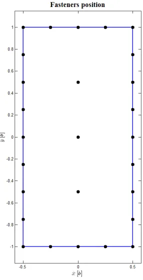
A timber framed wall is characterized by a timber frame made with solid timber studs and beams. The frame is braced against horizontal loads by sheathing panels connected to the frame itself by means of fasteners (nails or staples). For a single panel wall (the length wall l is equal to the panel length b) the horizontal displacement ∆sh caused by the deformation of fastener (see, Figure 3.3, III) can be evaluated, according to [Girhammar and Kallsner, 2009] as follows:
2
2 2
1 1
1
1
sh n n
c i i i i
F h
k
x
y
= =
⋅
∆ =
⋅
+
∑
∑
(3.7) where:• F: is the external horizontal force;
• h: is the height of the wall. The height of the sheathing panel is assumed in the
analysis equal to the height of the wall;
• xi , yi: are the fasteners’ coordinates with respect to a reference system with the
origin in the centre of the panel;
• n: is the number of fasteners;
Assuming a constant spacing of fasteners along the beams sp, on the perimeter studs sps and on the inner studs, we obtain:
2 2 1
1
1 3
6
n p ii ps p
s
h
b
x
b
s
b
s
=
≅ ⋅ + ⋅
⋅
⋅
⋅
∑
(3.8) 2 2 11
6
2
12
n p p ii ps is p
s
h
s
h
b
y
h
s
b
s
b
s
=
≅
⋅
+ ⋅
⋅ +
⋅
⋅
⋅
∑
(3.9)The ratio between the panel height h and the panel length b is defined as the panel geometrical parameter α. It is obtain as:
h
b
α
=
(3.10)The fastener spacing on the inner stud sis is assumed usually double than the fastener spacing on the perimeter studs sps and on the beams sp . For this reason a reference fastener spacing sc can be defined as:
Moreover the parameters η and ξ are defined:
2
isc ps p
s
(
)
1
1 3
6
η
= ⋅ + ⋅
α
(3.12)2
5
6
12
2
α
ξ
=
⋅
+ ⋅
α
(3.13)Hence, equations (3.8) and. (3.9) can be rewritten as:
3 2 1 n i i c
b
x
s
η
=≅ ⋅
∑
(3.14)3 2 1 n i i c
b
y
s
ξ
=≅ ⋅
∑
(3.15)Therefore, the horizontal displacement ∆sh is:
2 2 3
1
1
=
c sh cs
F b
k
α
η ξ
b
⋅
∆
⋅ ⋅
+
⋅
(3.16)At this stage we can define a new parameter λ depending on α, as:
2
1
1
=
= ( )
( )
( )
λ α
λ α
η α
ξ α
⋅
+
(3.17)The displacement
∆
sh becomes:=
( )
csh c
s
F
k
λ α
b
Equation (3.18) represents to the horizontal displacement due to the sheathing-to-framing fastener deformation for a wall whose length is equal to the panel (“single panel wall”). When a wall is characterized by several sheathing panels, eq. (3.18) can be rewritten as:
=
( )
csh c
s
F
k
λ α
l
∆
⋅
⋅
(3.19)The eq. (3.19) is developed assuming that the sheathing panels superimposition occurs only on one side of the wall. Therefore a more general expression can be obtained, considering also the case for which sheathing panels are superimposed on both sides of wall. Hence we get:
( )
=
csh
c bs
F
s
k
l n
λ α
⋅
⋅
∆
⋅ ⋅
(3.20)where nbs is the number of the sides of the wall where sheathing panels are superimposed (equal to 1 or 2).
The shape function λ, function of α is plotted in Figure 3.2. For values of 1< <αααα 6, λ, can be approximated by the linear equation (3.21).
( ) = 0,81 1,85
Figure 3.2: Shape function vs panel geometrical ratio
For the value of
α
=
2
, λ is equal to 4.52 as obtained by [Girhammar and Kallsner, 2009].3.1.4 Rigid-body translation
A timber-framed wall is usually connected to the foundation by means of angle-brackets or screws in order to prevent its rigid-body translation, see
Neglecting the friction, the deformation source due to the rigid-body translation ∆a can be calculated (see, Figure 3.3, IV) intuitively as:
=
aa a
F
k n
∆
⋅
(3.22)where:
•
k
a: is the stiffness of each angle-brackets (or screw);•
n
a: is the number of angle-brackets (or screws).=
aa
l
n
i
(3.23)Equation (3.22) can be rearranged as:
=
aa a
F i
k l
⋅
∆
⋅
(3.24)3.1.5 Total elastic horizontal displacement
The elastic horizontal displacement (Point C, Figure 3.1) of a timber frame wall subjected to a horizontal force shear wall can be obtained by adding the displacements caused by the four sources previously described. We get:
=
sh h a p∆ ∆ + ∆ + ∆ + ∆
(3.25)=
2
c a
bs c h a p bs p
F s
h
F h
q
F i
F h
l n
k
l k
l
k l
l G n
t
λ
⋅ ⋅
⋅
⋅
⋅
∆
⋅ ⋅
+
⋅
⋅
−
+
⋅
+
⋅ ⋅ ⋅
(3.26)Figure 3.3:Timber frame deformation contribution: rigid-body rotation (I), Sheathing-panel shear deformation (II), Sheathing-to-framing connection (III) and Rigid body translation (IV)
3.2 Horizontal stiffness of a timber frame wall
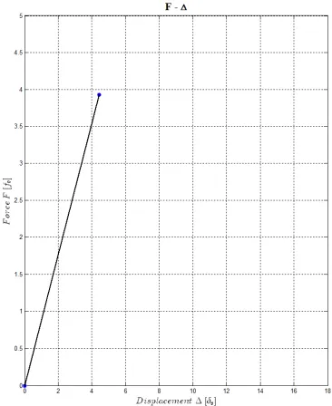
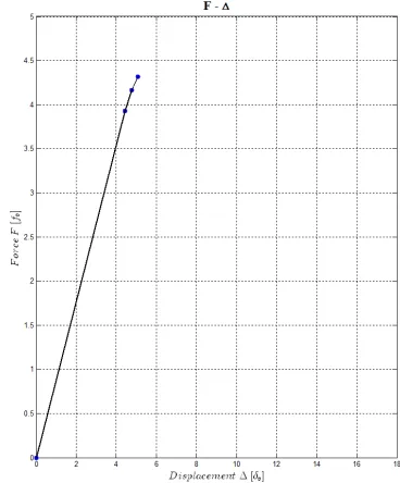
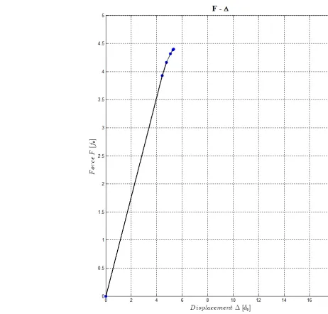
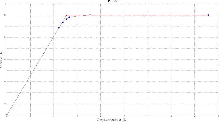
Figure 3.4: Force vs displacement curve
Referring to the second regime, the total horizontal displacement ∆, see Eq. (3.26), can be rewritten to highlight the contribution of the external force F, as shown by eq. (3.27):
=
SH P A H h
F
F
F
F
N h
K
K
K
K
l k
⋅
∆
+
+
+
−
⋅
(3.27)where:
• the sheathing panel global stiffness is:
=
p bs p PG
n
t
l
K
h
⋅
⋅ ⋅
(3.28)
• the sheathing-to-framing fastener stiffness is:
=
bs c SHn
k l
K
s
λ
⋅ ⋅
a a a a
A
k
n
i
l
k
K
=
⋅
=
⋅
(3.30)• the rigid body rotation stiffness is:
2 2
=
h
l
k
K
h HD⋅
(3.31)• the vertical load acting on the outer studs is:
2
=
q
l
N
⋅
(3.32)The global stiffness Ktot of the wall is hence defined as:
1
1
1
1
1
=
tot SH P A H
K
K
+
K
+
K
+
K
(3.33)while the backwards horizontal displacement ∆N of the wall due to the vertical load is :
h N
k
l
h
N
⋅
⋅
∆
=
(3.34)Thus, the horizontal displacement of the wall can be expressed as:
N tot
K
F
∆
−
∆
=
(3.35)=
tot(
N) =
tot NF
K
⋅ ∆ + ∆
K
⋅ ∆ +
F
(3.36)where FN is the equivalent horizontal force due to the vertical load.
A representation of the Equation (3.36) is shown in Figure 3.5. The elastic behaviour of a timber frame wall is represented by a rheological model characterize by four elastic springs in series subjected to an external total force equal to F −FN.
Figure 3.5: Wall rheological model for the elastic behaviour of a timber frame wall in the second regime
Equations (3.35) and (3.36) prompt the following two considerations
1. The horizontal displacement produced by the horizontal force F is decreased at a rate caused by the vertical load equal to
∆
N, which is constant.2. The force F depends on of two different quantities: the elastic force
∆
⋅
TOTK
and the force to counteract the vertical loadK
tot⋅
∆
N.The first regime (when the hold-down is not in tension), may be considered as a subcase of the first regime, setting the hold-down stiffness kh equal to infinity. Hence, the global stiffness Ktot,nt. of the wall is rewritten as::
,
1
1
1
1
1
=
lim
=
kh
tot nt tot P SH A
,
=
tot ntF
K
∆
(3.38)In this case the rheological model is represented by three springs in series, neglecting the contribution due to the rigid rotation. The acting force is equal to F (Figure 3.6).
Figure 3.6: Wall rheological model for the elastic behaviour of a timber frame wall in the first regime
3.3 Parametric study of the wall stiffness
In common practice, as explained in Chapter 2, the stiffness is assumed is linearly proportional to the wall length. In order to demonstrate that this assumption cannot be taken for granted, a dimensionless parametric study was performed. Regarding the second regime the global wall stiffness can be rewritten as:
h a a c bs c p bs p
tot
l
k
h
l
k
i
k
n
l
s
t
n
G
l
h
K
⋅
⋅
+
⋅
+
⋅
⋅
+
⋅
⋅
⋅
1
2 2=
1
λ
(3.39)
Four new parameters are defined to isolate the contribution of the length of the wall , namely:
1
=
=
p bs p P
h
l
G
n
t
K
1
=
c=
bs c SH
s
l
n
k
λ
K
β
⋅
⋅
(3.41)A a a
K
l
k
i
=
=
1
ϕ
(3.42) H hK
l
k
h
2 2=
=
1
δ
(3.43)Hence equation (3.39) becomes:
2
1
1
1
1
=
1
l
l
l
l
K
totϑ
⋅
+
β
⋅
+
ϕ
⋅
+
δ
⋅
(3.44)Equation (3.44) shows that the stiffness of the wall is not linearly proportional to the wall length. Unlike all other components the rigid-body rotation deformation is in fact linearly proportional to the square of the length influencing the relationship between the global stiffness and the length of the wall.
When the hold-down is not in tension, the parameter
δ
→
∞
. The wall stiffness is hence given by:l
l
K
K
totnt tot⋅
⋅
+
⋅
+
⋅
⋅
⋅
⋅
∞→
ϑ
β
ϑ
ϕ
β
ϕ
ω
ϕ
β
ϑ
δ
lim
=
=
=
, (3.45)
3.4 Finite element modelling of a timber-frame wall
Two numerical modelling suitable to investigate the linear elastic behaviour of timber wall under an horizontal external force are presented in this section. These are characterized by a different complexity and for this reason may be employed for different purposes.
The former was implemented in order to validate the results of the analytical predictive model (complete model) The latter, much simpler, is based on the results of the analytical predictive model and can be employed for global elastic linear analyses of series of walls or buildings (simplified model).
3.4.1 Complete model
The model is defined as “complete” since each significant deformation contribution is appropriately represented by an element (Figure 3.7).
Figure 3.7:Complete numerical model
fastener deformation contribution. The bottom beam is restrained by means of a vertical and a horizontal linear springs in order to represent respectively the in-tension hold-down and the angle brackets.
In order to validate the equation proposed for the calculation of the wall horizontal displacement, several analyses were performed changing the geometrical properties, the spacing of the fasteners and the stiffness of each connection device. An extensive description of the model and the results are reported in [Conte et al., 2011].
3.4.2 Simplified model
The complete model is characterized by a large number of degrees of freedom because each fastener is represented by two perpendicular linear –elastic springs. Based on the predictive analytical model described in previous sections a simplified model is presented (Figure 3.8) in order to represent the contribution of deformation of all fasteners by means of a single horizontal spring, reducing considerably the number of degrees of freedom of the model. This may be really significant when a series of walls (or an entire building) is to be modelled. As an example, a 2.5 m (length l) x 2.5 m (height h) wall characterized by sheathing panels (b=1.25 m) on both sides (nbs=2) with a fastener spacing (s) of 125 mm needs a number of fasteners equal to:
2.5
2.5
2.5
=
2
2
2
2
2
240
0.125
1.25 0.125
fasteners bs
l
l h
n
n
s
b s
⋅ + ⋅ ⋅ ⋅
=
⋅ +
⋅
⋅ ⋅ =
(3.46)The number of degrees of freedom are hence equal to 480. For this reason the reduction factor r is equal to:
1
=
0.0021
480
r
=
(3.47)=
P SH SPP SH
K
K
K
K
K
⋅
+
(3.48)The stiffness of the frame timber elements must be assumed as infinite in order to prevent its bending deformation.
Figure 3.8: Simplified model for in-tension hold-down
As for the complete model, a vertical spring with stiffness equal to kh is used to represent the hold-down while a horizontal spring with stiffness KA models the rigid body translation contribution.
4
ELASTO-PLASTIC ANALYSIS OF A TIMBER -FRAME WALL
UNDER A HORIZONTAL FORCE
acceptable time-consuming of the analysis. The development of this spring in the non-linear range was investigated via a parametric study in which the variables were the sheathing panel’s aspect ratio and the fastener spacing. By also considering equivalent springs for the other components (as in the linear range), it has been possible to define a rheological model for elasto-plastic behaviour of a sheathed timber frame as function of the mechanical properties of the fasteners, hold-downs and angle brackets. Particular attention has been paid to the relationship between component (e.g. fastener) ductility and the global ductility of the wall. Use of this approach to underpin nonlinear numerical modelling of seismic response of multiple timber frame walls is discussed. This then feeds into assessment of seismic capacity of timber-frame walls and hence of timber buildings.
4.1 Rheological model for the assessment of the non-linear behavior of a timber-frame wall
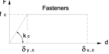
According to the simplified model describe in Chapter 3 the behaviour of a timber-frame wall under a horizontal force F and a distributed vertical load q, can be represented by a simple pinned frame, braced by a horizontal spring of stiffness equal to KSH representing the sheathing-to-framing connection (when the contribution of the sheathing panel KP is neglected, KPS is equal to KSH). The contribution of the devices which prevent the horizontal translation of the wall is represented by horizontal spring of stiffness KA connected to the ground, while the rigid body rotation, (hold-down contribution) is taken into account by means of a vertical spring of stiffness equal to kh.
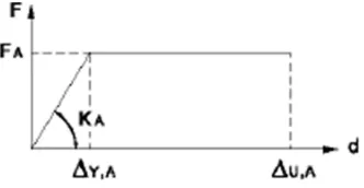
The implementation of this model in the non-linear range is quite simple and straightforward: each spring (sheathing-to-frame, rigid body translation and rigid body rotation) is not characterized simply by its linear stiffness but by a non-linear curve. In this thesis an elasto—plastic behaviour of each source is assumed: the force vs displacement curve of each spring is hence characterized simply by its stiffness, strength and ductility. In this case, the non-linear mechanical behaviour of the wall is therefore described by a bi-linear or tree-linear curve.
rigid translation KA) and a third in-series element, made up by a horizontal spring KH (representing the rigid body rotation) placed parallel to a friction block (Fq) representing the vertical load contribution (Figure 4.1).
Figure 4.1Timber frame rheological model
4.2 Mechanical properties of sources of deformation
In this section some analytical expressions are proposed for the definition of elasto-plastic behaviour of each component of the rheological model. The calculation is based on the knowledge of the mechanical properties of the fasteners and the connection devices of each source of deformation.
4.2.1 Rigid body rotation
Figure 4.2: Rigid body rotation and vertical load component
The hold down device, used in order to prevent the rigid rotation of the wall, is loaded by a tensile force only when the overturning moment, caused by the horizontal force F is greater than the stabilizing moment, resulting from vertical load q. This condition occurs when:
2
=
=
2
l
q
M
h
F
M
ovt stb⋅
≥
⋅
(4.1)As described in chapter 3, the value Fq of the horizontal force for which the hold down is subjected to a tensile force is given by:
h
l
q
F
q⋅
⋅
2
=
2
(4.2)
4.2.2 Friction block
The friction block is used in the rheological model to represent the stabilizing contribution of the uniform vertical load q and in particular the condition for the activation of the rigid rotation source. Its mechanical behaviour is described by a rigid indefinite perfectly plastic curve, as shown in Figure 4.3. The force for the yield of the block is equal to Fq.
Figure 4.3: Block friction component
4.2.3 Horizontal non-linear spring for the rigid-body rotation of the wall
Figure 4.4: Rigid body rotation component and elasto-plastic behaviour
Figure 4.5: Hold down elasto-plastic behaviour
The analytical expressions for the calculation of the mechanical parameters that characterize the horizontal non-linear spring of the rheological model can be obtained by some geometrical and mechanical considerations, isolating the deformation contribution of the hold down. The strength FH can be directly calculated from the strength of the hold-down strength fH as:
h
l
f
n
F
hh H
⋅
⋅
=
(4.3)where:
•
f
h is the hold down strength;• l is the length of the wall;
•
n
h is the number of hold downs for each corner of the wall.The yield displacement ∆y,H can be related to the hold down yield displacement δy,H by according to equation (4.4):
h
l
h y H Y⋅
∆
, ,=
δ
(4.4)The stiffness KH is therefore given by:
2 2
2
, , ,
=
H=
h=
h=
H h h h h
Y H y h y h
f
l
f
F
l
l
l
K
n
n
n
k
h
δ
h
δ
h
h
⋅
⋅
⋅
⋅
⋅
⋅ ⋅
∆
⋅
(4.5)As for the yield d