Bone Tissue Engineering: structures and strategies
for functional sca
ff
old design and evaluation
Matteo Stoppato
E-mail: [email protected]
Advisors:
Dr. Antonella Motta Dr. Eleonora Carletti Prof. Robert E. Guldberg
Ph.D. Commission: Prof. Claudio Migliaresi Dr. Pranesh Aswath Prof. Orfeo Sbaizero Dr. Arthur J Coury
University of Trento,
Department of Industrial Engineering
Abstract 1
1 Introduction 3
1.1 Extracellular matrix . . . 3
1.1.1 ECM functions . . . 4
1.1.2 Biochemical properties . . . 4
1.1.3 Physical properties . . . 5
1.1.4 Mechanical transduction . . . 6
1.2 Bone composition and morphology . . . 8
1.2.1 Collagen . . . 10
1.3 Bone healing . . . 13
1.3.1 Stage 1: inflammation . . . 13
1.3.2 Stage 2: soft callus formation . . . 14
1.3.3 Stage 3: hard callus formation . . . 14
1.3.4 Stage 4: bone remodeling . . . 14
1.4 Bone damage, degeneration and clinical treatment . . . 16
1.5 Tissue Engineering . . . 18
1.5.1 Scaffolds . . . 19
1.5.2 Materials . . . 20
1.5.3 Process techniques . . . 21
1.6 Bone tissue engineering . . . 24
1.7 Angiogenesis in tissue engineering . . . 25
2 Research strategies and objectives 27 2.1 Thesis rationale . . . 27
2.1.1 Scaffold fabrication . . . 28
2.1.1.1 Materials . . . 28
2.1.2 Cells . . . 34
2.1.2.1 MG63 . . . 34
2.1.2.2 hMSC . . . 35
2.1.2.3 HUVEC . . . 35
2.1.3 Animal model . . . 36
2.2 Outline and objectives . . . 37
3 Functional role of scaffolds with different geometries as a template for physiological callus formation: evaluation of collagen 3D assembly 39 3.1 Abstract . . . 39
3.2 Introduction . . . 41
3.3 Materials and Methods . . . 43
3.4 Results and Discussion . . . 48
3.5 Conclusions . . . 56
4 Influence of scaffold pore size on type I collagen development: a new in vitro evaluation perspective 57 4.1 Abstract . . . 57
4.2 Introduction . . . 58
4.3 Materials and Methods . . . 60
4.4 Results . . . 66
4.5 Discussion . . . 74
4.6 Conclusions . . . 77
5 Effects of silk fibroin fiber incorporation on mechanical properties, en-dothelial cell colonization and vascularization of PdlLA scaffolds 79 5.1 Abstract . . . 79
5.2 Introduction . . . 80
5.3 Materials and Methods . . . 82
5.4 Results . . . 88
5.5 Discussion . . . 97
5.6 Conclusions . . . 100
6 Human Mesenchymal Stem Cells Seeded onto PdlLA Scaffolds: Influ-ence of Addition of Silk Fibroin Fiber and Endothelial Cells 101 6.1 Abstract . . . 101
6.3 Materials and Methods . . . 104 6.4 Results and Discussions . . . 108 6.5 Conclusions . . . 116
7 Conclusions 117
Bibliography 119
Scientific Production 141 Partecipation to Congresses and Schools 143
Other activities 145
1.1 Bone morphology . . . 9
1.2 Representation of collagen assembly. . . 11
1.3 A representative series of images of the four-stage model of fracture
healing. Adapted from Schindeler et al.[1] . . . 13
1.4 Neovascularization encompasses both angiogenesis and
vasculogen-esis. Angiogenesis represents the classic paradigm for new vessel growth, as mature, differentiated endothelial cells form sprouts from parental vessels. Vasculogenesis involves participation of endothe-lial progenitor cells that, recruited, form new blood vessels. Images adapted from Isner at al.[2]. . . 26
2.1 The two stereoisomeric forms of lactic acid: PdLA and PlLA. . . 28
2.2 Scanning electron micrograph of a partial degummed silk filament. . 29
2.3 Typical amino acid sequence of fibroin. . . 30
2.4 On the left the polymer extrusion from the metal micro-needle. On
the right typical microfabricated scaffolds. . . 31
2.5 Scanning electron microscopy images of PdlLA microfabricated
scaf-folds obtained changing polymer solution concentrations. . . 32
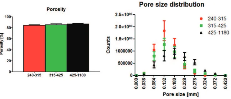
2.6 On the top scanning electron microscopy images of PdlLA sponges.
Scale bars = 100 µm. On the bottom micro-CT color-coded pore
diameter scale images. NaCl particulates with three different
dimen-sional ranges were used: (A) 240-315 µm, (B) 315-425 µm, and (C)
425-1180 µm . . . 33
2.7 On the left porosity of the three scaffolds. On the right pore size
profile of the three scaffolds. . . 34
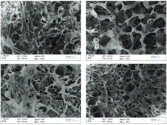
2.8 Scanning electron microscopy images of PdlLA sponges with SF fibers.
3.1 Scanning electron microscopy images of PdlLA scaffolds: (A) micro-fabricated scaffold, (B) salt-leached sponge. . . 48
3.2 LDH assay of PdlLA scaffolds: salt-leached sponges and
microfabri-cated scaffolds are not cytotoxic. . . 49
3.3 AlamarBlue assay for MG63 cell culture on PdlLA scaffolds and
48-well culture plate used as control. . . 50
3.4 Confocal Laser Scanning Microscopy images of MG63 cells stained
with Rhodamine Phalloidin and DAPI adhered to PdlLA scaffolds
after A, B) 4 days, C, D) 7 days, E, F) 14 days, G, H) 21 days and I, K) 28 days of cell culture. On the left the microfabricated scaffolds, on the right the salt-leached sponges. Scale bars = 100 µm. . . 51
3.5 3D Confocal Laser Scanning Microscopy images of MG63 cells stained
with Rhodamine Phalloidin and DAPI adhered to PdlLA scaffolds
after A, B) 4 days, C, D) 7 days, E, F) 14 days, G, H) 21 days, and J, K) 28 days of cell culture. On the left the microfabricated scaffolds, on the right the salt-leached sponges. Stack depths are specified. . . . 53
3.6 SEM images of the PdlLA scaffolds after A, B) 21 days, C, D) 28 days of cell culture. On the left the microfabricated scaffolds, on the right the salt-leached sponges. Arrows indicate cell bridging mechanism and spreading behavior. Different magnification are reported. . . 54
3.7 Confocal Laser Scanning Microscopy images of MG63 cells stained
with Direct Red 80 adhered to PdlLA scaffolds after A, B) 4 days,
C, D) 7 days, E, F) 14 days, G, H) 21 days, and J, K) 28 days of cell culture. On the left the microfabricated scaffolds, on the right the salt-leached sponges. Scale bars = 100 µm. . . 55
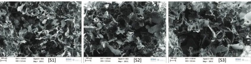
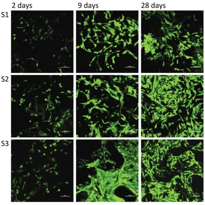
4.1 Scanning electron microscopy images of PdlLA scaffolds. Sieved NaCl
particulates with three different dimensional ranges were used: (S1)
240-315 µm, (S2) 315-425 µm, and (S3) 425-1180 µm. Scale bars =
100 µm. . . 66
4.3 Confocal Laser Scanning Microscopy images of MG63 cells stained with CalceinAM. S1, S2 and S3 at 2, 9 and 28 days after cell seeding are shown. Scale bars = 100 µm. . . 68
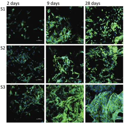
4.4 Confocal Laser Scanning Microscopy images of MG63 cells stained
with Dapi and Oregon Green 488 Phalloidin. S1, S2 and S3 at 2, 9
and 28 days after cell seeding are shown. Scale bars = 100 µm. . . 69
4.5 (A) Collagen amount in the three scaffolds at the different time points (B) Quantitative PCR analysis of Collagen I gene expression in cells cultured into the three scaffolds at the different time points. t, p < 0.05 vs the same scaffold at the previous time point; *, p < 0.05 vs
S1 at the same time point; ^, p < 0.05 vs S2 at the same time point. 70
4.6 Confocal Laser Scanning Microscopy images of the three constructs
(S1, S2 and S3) stained with a specific antibody for collagen I. Images of 2, 9, 20 and 28 days after cell seeding are reported. Scale bars = 100 µm. . . 71
4.7 RT-qPCR analysis of RUNX2 (A) and Decorin (B) gene expression
in cells cultured into the three scaffolds at the different time points. t, p < 0.05 vs the same scaffold at the previous time point. . . 72
4.8 Stereo microscopy images of the three constructs (S1, S2 and S3)
stained with AlizarinRed (calcium deposition stained red). Images of 5, 9, 20, and 28 days after cell seeding are reported. Arrows indicate calcium deposition. Scale bars = 500 µm. . . 73
5.1 (A) From left to right: Scanning electron microscopy images,
cross-sectional micro-CT slices and color-coded pore diameter scale images of the two scaffolds. (B) Porosity of the two scaffolds. (C) Pore size profile of the two scaffolds. (D) Degree of anisotropy of the two
scaffolds. Group 1: PdlLA salt-leached sponge; Group 2: PdlLA
salt-leached sponge with silk fibroin fibers. . . 88
5.2 (A) Stress–strain plot of a representative compressive mechanical
test-ing for a PdlLA salt-leached sponge scaffold with linear fit slope
shown. (B) Elastic moduli of wet scaffolds after immersion in PBS
5.3 (A) HUVEC cell number. *, p < 0.05. (B) Viability index for HUVEC cell culture (normalized to cell number). $, p < 0.05 vs the same
scaffold at the previous time point. Group 1: PdlLA salt-leached
sponge; Group 2: PdlLA salt-leached sponge with silk fibroin fibers. 91
5.4 RT-qPCR analysis of VWF and PECAM-1 gene expression in cells
seeded onto the scaffolds at different time points: (A), 7 days; (B), 21 days. No significative differences are present (n=3). Group 1: PdlLA salt-leached sponge; Group 2: PdlLA salt-leached sponge with silk fibroin fibers. . . 92
5.5 Confocal Laser Scanning Microscopy images of HUVEC cells stained
for nuclei (DAPI, blue) and PECAM-1 (red). Group 1 and Group 2 at 7, 14 and 21 days after cell seeding are shown. Silk fibroin fibers
stain with DAPI. Scale bars = 100 µm. Group 1: PdlLA salt-leached
sponge; Group 2: PdlLA salt-leached sponge with silk fibroin fibers. 93
5.6 Histological images of sections (5μm) of explanted scaffolds. Left pic-tures (A) show samples stained with hematoxylin and eosin at 3 and 6 weeks with sample at 3 weeks perfused with vascular contrast agent. Black arrows indicate multinucleated giant cells. Right pictures (B) show samples stained with picrosirius red at 3 weeks. Center area indicates an inner part of the implants, edge area the interface
be-tween the implants and newly formed tissue. Scale bars = 100 µm.
Vascular contrast agent is also seen in the center area images in B. Group 1: PdlLA salt-leached sponge; Group 2: PdlLA salt-leached sponge with silk fibroin fibers. . . 94
5.7 (A) Micro-CT images of scaffold implanted subcutaneously in rat
perfused with Microfil vascular contrast agent. Vasculature (dark grey) growing into implant area (light grey), (B) Quantification of vascular volume/total scaffold volume. *, p< 0.05 (C) Representative scans of blood vessels 3 and 6 weeks after implantation. Color scale bars, defining vessel diameters, range from 0 to 320 µm at 3 weeks to
0 to 240 µm at 6 weeks. Group 1: PdlLA salt-leached sponge; Group
5.8 (A) Vascular connectivity, (B) Number of vessels and (C) Degree of anisotropy of scaffolds at 3 and 6 weeks after implantation.*, p< 0.05. Group 1: PdlLA salt-leached sponge; Group 2: PdlLA salt-leached sponge with silk fibroin fibers. . . 98
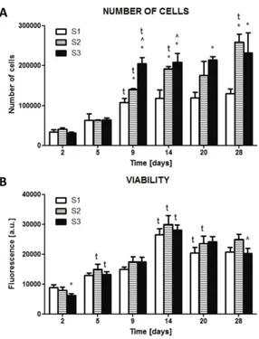
6.1 Cell number normalized for the number of cells at day 1. *, p< 0.05 vs the Group1 (hMSC): #, p< 0.05 vs the Group1 (hMSC+HUVEC); @, p< 0.05 vs the Group2 (hMSC). Group 1: PdlLA salt-leached
sponge; Group 2: PdlLA salt-leached sponge with silk fibroin fibers. 108
6.2 Viability index for cell culture (viability normalized to cell
num-ber). *, p< 0.05 vs the Group1 (hMSC): #, p< 0.05 vs the Group1 (hMSC+HUVEC); @, p< 0.05 vs the Group2 (hMSC). Group 1: PdlLA salt-leached sponge; Group 2: PdlLA salt-leached sponge with silk fibroin fibers. . . 109
6.3 Confocal Laser Scanning Microscopy images of the samples stained
with a specific antibody for collagen I. Images of 7 and 21 days after cell seeding are reported. Group 1: PdlLA salt-leached sponge; Group 2: PdlLA salt-leached sponge with silk fibroin fibers. Scale bars = 100 µm. . . 110
6.4 ALP activity. *, p< 0.05 vs the Group1 (hMSC): #, p< 0.05 vs
the Group1 (hMSC+HUVEC); @, p< 0.05 vs the Group2 (hMSC). Group 1: PdlLA salt-leached sponge; Group 2: PdlLA salt-leached sponge with silk fibroin fibers. . . 111
6.5 Volcano plot with significant gene expression changes between Group
1 scaffolds seeded with hMSCs and Group 1 scaffolds seeded with
hMSC and HUVECs. Group 1: PdlLA salt-leached sponge. . . 112
6.6 (A) Quantification of the mineralization. *, p< 0.05 vs the Group1
(hMSC): #, p< 0.05 vs the Group1 (hMSC+HUVEC); @, p< 0.05 vs the Group2 (hMSC). Group 1: PdlLA salt-leached sponge; Group 2: PdlLA salt-leached sponge with silk fibroin fibers. (B) Micro-CT images of mineralized scaffolds after 6 weeks of cell culture. . . 113
6.7 Histological images of sections (5 μm) of scaffolds. Samples were
stained with von Kossa at 6 weeks. Arrows show granular microde-posits of phosphate. Group 1: PdlLA salt-leached sponge; Group 2: PdlLA salt-leached sponge with silk fibroin fibers. Scale bars = 100
6.8 Volcano plot with significant gene expression changes between Group
1 scaffolds seeded with hMSCs and HUVECs and Group 2 scaffolds
seeded with hMSC and HUVECs. Group 1: PdlLA salt-leached sponge; Group 2: PdlLA salt-leached sponge with silk fibroin fibers. . 115
6.9 Confocal Laser Scanning Microscopy images of cells stained for nuclei
Skeletal tissue has a good ability to self-regenerate after injury through the processes of bone healing. However, bone can suffer from a wide range of pathologies, cancers or congenital defects which lead to loss of bone mass and density.
Current progresses in tissue engineering have shown great potential for creating bi-ological alternatives and new perspectives for the treatment of bone damage and defects. In this approach, scaffolding plays a pivotal role. In particular, the prin-ciples of biomimesis have to be followed and the scaffolds have to be designed to this purpose. Furthermore, these tissue engineered systems have not only to sup-port and guide the new tissue formation, but they have to induce a complete tissue functionality.
The aim of this research work was the application of these advanced principles to produce and evaluate scaffolds for bone regeneration.
Starting from the idea to mimic the extracellular matrix (ECM), template that characterizes the early step of the bone healing process, we design scaffolds for the evaluation of biological outputs considering the initial ECM produced by cells. We used two polymers, naturally (silk fibroin) or synthetically (poly-d,l-lactic acid) derived, and we modulated scaffold geometry (random vs ordered pore distribution), pore size and chemical composition, combining spongy and fibrous structures.
The scaffolds were indeed considered as models, to investigate if they control cell production of type I collagen, principle component of the natural template for the final mineralization. Moreover, due to the key role of vessel formation in tissue engi-neering and the correlation between osteoblasts and endothelial cells, the influence of the scaffolds on angiogenesis and vascularisation was assessed.
1.1 Extracellular matrix
The extracellular matrix (ECM) is the major component of the cellular microen-vironment, or niche. The principal constituents of ECM are fibrous proteins with a support function (i.e. collagens, fibronectin, laminins, vitronectin, elastin), other specific proteins (i.e. growth factors, small matricellular proteins and small integrin-binding glycoproteins), proteoglycans (PGs) and water. Physical, mechanical and biochemical properties of tissues depend on the specific assembling and concentra-tion of these constituents [3]. ECM undergoes to a continuous remodeling driven by cells that cleave, rearrange and deposit the different components and define the tissue architecture, with reciprocal interactions.
All cells are in connection with their ECM, either continuously or at certain stage of their life, such as at stem or progenitor cell phase or during cell migration and proliferation.
ECM most evident role is related to its scaffolding/template function for cells and tissues. In fact it can guide and regulate cell activity (i.e. proliferation, adhesion, migration, differentiation, apoptosis and gene expression) through patterned chem-ical signals (ligands) properly exposed to cell receptor (transmembrane proteins) as well as mechanical and structural stimuli [4].
The complex mechanism of ECM remodeling allows regulation of stem cell diff
er-entiation and it is central during growth and wound healing. Moreover, anomalous ECM dynamics generate a deregulation of cell activities, resulting in congenital de-fects and causing pathological tissue growths (fibrosis and cancer). Understanding and regulating the remodeling mechanisms of ECM is strategic for tissue engineering and regenerative medicine perspectives [5].
1.1.1 ECM functions
ECM defines the functional organ architecture while acting as bioactive substrate
for cell adhesion, migration, growth and differentiation. Moreover, ECM serves
as storage for molecules and growth factors, transmits and distributes the loads preventing mechanical failure, partitions and distributes cells in specific functional units [6].
The chemical composition, architecture, physical and mechanical properties of ECM vary according to the tissues and their specific developmental stage, age, pathological state and during the wound healing process.
1.1.2 Biochemical properties
ECM is typically a highly hydrated macromolecular network composed of various amounts of proteins and proteoglycans.
All macromolecular components of the ECM are synthesized by cells and subse-quently secreted in the extracellular space where further physical-chemical modifi-cations can take place.
Nearly all of the proteins are glycoproteins [7], characterized by oligosaccharide chains covalently attached. Most of them are fibrous structural proteins and include the large family of collagens, laminins, fibronectins and nidogens. Elastin is also a protein but without chains of carbohydrate residues attached. Proteoglycans are other proteins but consist of big clusters of carbohydrate chains, glycosaminoglycans (GAGs), attached to a core protein. Some examples are heparin sulphate (which regulates a wide variety of biological activities, including developmental processes, angiogenesis and blood coagulation), chondroitin sulphate (which is considered to stabilize brain synapses), and keratin sulphates (which are involved in various tissues development and wound healing). Among the GAGs, hyaluronic acid (HA) does not have a protein component. HA has many functions: it stimulates cytokine and angiogenesis, attracts water, influences damaged or growing tissues and allows nutrients and metabolites diffusion. Moreover, particularly during embryogenesis, hyaluronic acid creates cell-free space filled with water into which cells can proliferate and migrate.
force-resistance properties [8].
GAGs can bind to a myriad of growth factors and they can control the diffusive range and accessibility of ligands to their receptors. Heparan sulphate proteoglycan, for example, facilitates interactions between ligands and their receptors and has the capability to bind to various growth factors [9].
ECM acts as a molecular “reservoir” binding to ligands and creating a concentration gradient of many growth factors produced by cells, such as bone morphogenetic pro-teins (BMPs), fibroblast growth factors (FGFs), hedgehogs (HHs), and Wnt propro-teins (signaling molecules that control cell-cell communication) [10, 11].
It is widely recognized that the unique chemical composition of each tissue, due to the mix of the components described, maintains biological and biochemical infor-mation, guiding cells behavior and tissue organization.
1.1.3 Physical properties
The physical properties of ECM refer to its morphology (i.e. shape, structure, poros-ity, pattern), topography (related to the surface), water content, and biomechanical characteristics. ECM has a clear structural function, fundamental in connective tis-sues, but still significant in all the other tissues where a support for cell is provided.
Some of the ECM proteins, such as collagens and elastin, are organized in fib-rils/fibers forming the ECM skeletal structure and providing the tensile strength and viscoelasticity of the tissue. The network solidity is instead guaranteed by linking proteins, working as natural crosslinkers, including collagens, fibronectin, laminin, and nidogen [3, 4, 11].
The most evident role of ECM is related to its scaffolding/template support func-tion. More generally, ECM supports tissues structure, ensuring their integrity and favoring cell anchorage and migration or, in the case of basement membrane, cre-ating a barrier for cells and factors migration [4, 10, 12, 13, 14, 15]. The cell-ECM constant interaction is fundamental to maintain the proper ECM composition and assembling, which, in turn, can promote cell movement and orientation. It has been demonstrated the importance of the ECM structure on the formation of tissue during its healing process and, in particular, that the orientation of collagen fibrils can significantly impact on cell arrangement and, consequently, on matrix formation [16, 17].
elastic proteins) embedded in a of porous hydrated gels matrix of glycosaminoglycans (GAGs). The ratio between the constituents varies according to the tissue.
GAGs and proteoglycans can combine to form huge polymeric complexes, and they are also connected with fibrous matrix proteins (i.e. collagen) and with protein networks (i.e. basal lamina), creating a continuous complex fiber arrangement [18, 19, 20]. GAGs tend to arrange in a highly extended conformations that occupy a large volume, forming gels even at low concentrations. The high density of negative charges in the chain attracts cations,N a+
, that are osmotically active, thus forcing a large amounts of water into the matrix. This creates a swelling pressure, that enables the matrix to withstand compressive forces (in contrast to collagen fibrils, which resist stretching forces). As mentioned before, one of the main glycosaminoglycans is the hyaluronic acid, also important for its resistance to compressive forces due to its capacity to attract water. Chondroitin sulphate is another glycosaminoglycan that contributes to the tensile strength of cartilage, tendons, ligaments and walls of the blood vessels.
The ECM biomechanical behavior describes the reaction of ECM to loads, such as compressive, tensile, bending, torsion and shear stresses applied by cells or external forces [21]. These loads have a great impact on the ECM characteristics, influencing its elasticity/rigidity. ECM mechanical properties range from those of soft and compliant structures, as in adipose tissue, brain, or muscles, to those of stiffand rigid tissues, as bones [22, 23]. Tissues clinical studies suggest that ECM elasticity plays a significant role in organ homeostasis and function, recognizing that diseased tissues have markedly altered elasticity compared to the healthy ones and that changes in tissue stiffness may indicate a pathologic condition [24, 25]. Indeed, the extent of tissue stiffness is often considered a good prognostic indicator for disease [8].
1.1.4 Mechanical transduction
Cells have indeed developed sophisticated mechanosensors and systems, such as fila-ments, integrins and cytoskeleton, connecting cells with ECM. In this way, external forces can modify nuclear architecture, chromatin organization and, consequently, gene expression and cell differentiation [27, 28, 29].
This means that external mechanical stimuli are transduced to cells through the ECM that they are connected to, then cells are able to convert sensed mechanical stimuli into biochemical pathways leading to different cell activities.
Part of such bidirectional communication between ECM and cells, is a result of a di-rect mechanical connection between fibrous protein in the ECM and cell cytoskeleton via integrins. Integrin-mediated cell-ECM interactions promote the assembly of cy-toskeletal and signaling molecule complexes at focal adhesion sites. These complexes include Src-family members, focal adhesion kinase (FAK), phosphatidylinositol-3´ -kinase (PI3K), and phospholipase C (PLC) [30, 31]. Accordingly, cells do not only exert forces, but also respond to the resistance sensed through cytoskeleton organi-zation/tension, triggering several intracellular signaling pathways [32].
In coordination, it seems that there is a synergy between mechanical stimuli and hormones, growth factors, and inflammatory mediators which collectively activate the same signalling pathways [29, 30, 33, 34, 35].
During development, ECMs are able to adapt to the higher mechanical demands, by increasing the size of the necessary tissue components [34, 36].
Furthermore, mechano-chemical transduction is altered in aging connective tissues. In fact, recent evidence suggests that tension applied by cells to ECM is reduced or lost during aging and diseases such as osteoarthritis [37]. The reduction observed is similar to changes that occur as a result of disuse [38].
1.2 Bone composition and morphology
Bone is a dynamic and highly specialized form of connective tissue. The main function of bone is to sustain and protect the soft tissues of the body, and it acts as a storage facility for systemic mineral homeostasis. Bone tissue is characterized by a unique composition which gives a marked rigidity and strength while still maintaining a good degree of elasticity.
The bone structure consists of approximately 65-70%w mineral, 20-25% protein, 8-9% water, and less than 1% cell amount [39]. Collagen constitutes approximately 95% of the organic matrix (which 99% is type I Collagen); the remaining 5% is composed of proteoglycans and numerous non-collagenous proteins.
The major component of bone is, however, mineral. The main bone mineral com-ponents are calcium phosphates, especially hydroxyapatite (Ca5(P O4)3(OH)). It forms prism crystals, with a length of 20 nm and a thickness of 2 nm. The presence of minerals combined with an appropriate distribution of collagen fibers in the ex-tracellular matrix provides strong mechanical properties in terms of hardness, and compressive, tensile, and torsion strength. From a material science perspective, it is possible to describe the bone properties as if it was a composite material due to its organic and inorganic components [40].
The relatively cell-free bone tissue comprises 4 different kinds of cells: osteoprogen-itor cells, osteoblasts, osteocytes, and osteoclasts. Osteoprogenosteoprogen-itor cells, deriving from periosteum, present a high proliferative ability and are able to differentiate in bone cells [41]. Osteoblasts tend to form sheets on the bone surface during tissue formation and their role is to secrete the type I collagen and the non-collagenous proteins, synthesizing and mineralizing new ECM. After the appropriate bone de-position, osteoblasts decrease their metabolism and finally differentiate into osteo-cytes. The osteocyte is the most abundant cell type of bone and is responsible for its maintenance and remodeling [42]. These cells have the capacity not only to syn-thesize, but also to resorb matrix to a limited extent. Each osteocyte occupies a space, or lacunae, within the matrix. Instead, osteoclasts are large (100-200 μm), multi-nucleated cells, developed from hemopoietic cells of the monocyte–macrophage lineage, that resorb bone. Active osteoclasts exhibit a characteristic polarity with nuclei typically locate in the part closer to the removed bone surface [43].
is influenced heavily by the individual’s mechanical loading history, acting both as constraints and as driving forces in its architecture [44, 45].
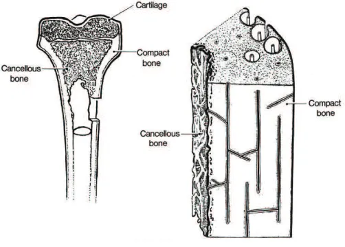
Figure 1.1: Bone morphology
Morphologically, there are two main types of bone: compact (cortical) and trabec-ular (cancellous or spongy). In compact bone, densely packed collagen fibrils form concentric lamellae, and the fibrils in adjacent lamellae run in perpendicular planes as in plywood. Trabecular bone has a loosely organized, porous matrix. Differences in the structural arrangements of the two bone types are related to their primary functions: cortical bone, more solid, provides mechanical and protective functions and trabecular bone, more porous, provides metabolic functions [39, 46].
Thanks to cell activity, bone tissue undergoes a continuous renewal in a delicate equilibrium between synthesis and degradation of the extracellular matrix. Its metabolism and regeneration are under the influence of a variety of molecules and local factors, such as Insulin-like Growth Factor (IGF), Fibroblast Growth Factor (FGF) and Bone Morphogenetic Protein (BMP).
1.2.1 Collagen
Collagen is the most abundant family of proteins constituting the extracellular ma-trix in animals and it represents one third of the total protein in humans [48, 49, 50]. Collagens are the major structural elements of all connective tissues and they provide stability and structural integrity of tissues and organs [51].
Collagen molecules form the characteristic fibrillar and micro-fibrillar networks con-tributing to the basement membrane structure as well as other structures of the extracellular matrix. If originally it was widely accepted that all collagens were secreted by fibroblasts in connective tissue, in the last decade, the knowledge on the collagen family increased considerably identifying that osteoblasts, numerous epithelial cells and other cell type are able to produce certain types of collagens [52].
So far, 28 genetically distinct collagen types have been described in vertebrates
[53, 54, 55, 56]. The different collagen types are characterized by considerable
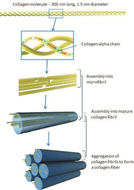
complexity and diversity in their structure, their splice variants, the presence of additional, non-helical domains, their assembly and their function. Based on their structure and supramolecular organization, they can be grouped in different fami-lies. The most widespread family of collagens with about 90% of the total collagen is represented by the fibril-forming collagens, comprising collagen types I, II, III, V, and XI. These collagens are characterized by their ability to assemble into highly orientated supramolecular aggregates with a characteristic suprastructure, with di-ameters between 25 and 400 nm. Type I contributes to the structural backbone of bone [57, 58] and it is the most abundant and best known.
The central feature of collagen is characterized by three parallel polypeptide chains (which generally consists of two identical chains and an additional chain that differs slightly in its chemical composition) arranged in a helical conformation. The amino acid composition of collagen results in a repeating X-Y-Gly sequence, where X and Y can be any amino acid (often proline and hydroxyproline) and Glycine is found at almost every third residue.
Figure 1.2: Representation of collagen assembly.
1.3 Bone healing
Bone healing is a process that combine certain aspects of skeletal development and growth involving a complex interplay of cells, growth factors and extracellular ma-trix. Conventionally the process is explained in four stages. In the early step, the cellular inflammatory reaction is followed by fibrocartilage tissue production (soft callus tissue). This is the natural fingerprint for the formation of hard callus, that is physiologically replaced by the final bone, either cortical or trabecular, remodeled and completed in an ultimate stage. During the repair process every newly formed tissue evolves from the previous and the entire healing mechanism results from the development of these overlapped stages [1, 62, 63, 64, 65, 66].
Figure 1.3: A representative series of images of the four-stage model of fracture healing. Adapted from Schindeler et al.[1]
1.3.1 Stage 1: inflammation
reorganized into granulation tissue. Macrophages, giant cells and other phagocytic cells clear degenerated cells and other debris. This cellular response is coordinated by the secretion of a range of cytokines and growth factors. The in situ scenery, when an inflammation condition is present, is extremely complex and not only cells and molecules are interested but also the ECM with its biophysical features and geometrical characteristics [1, 62, 67, 68, 69, 70].
1.3.2 Stage 2: soft callus formation
Fractures are usually characterized by some level of mechanical instability. Ossifi-cation is therefore preceded by a cartilaginous template, a soft callus, that provides a semi-rigid support to the fracture. Chondrocytes and fibroblasts are the cells responsible for the synthesis of the cartilaginous matrix, temporary plug between the fractured fragments, that is subsequently replaced. Chondrocytes, derived from mesenchymal progenitors, before going through apoptosis undergo hypertrophy and mineralize the cartilaginous matrix. An important role is played by the growth factors that guide fibroblast proliferation, chondrocyte behavior and regulate vas-cular morphogenesis of larger vessels and collateral branches from existent vessels [1, 62, 66].
1.3.3 Stage 3: hard callus formation
This stage is dominated on a cellular level by osteoblasts which differentiate from osteoprogenitors in the presence of osteogenic factors. The progenitor cells originate from many sources such as periosteum, bone marrow, vasculature and surrounding local tissues. During this step osteoblasts produce the woven mineralized bone ma-trix, starting in the stable areas of the soft callus. In order for bridging new hard callus, the unstable soft callus is gradually removed, concomitant with revascular-ization. The vasculature is a key point for formation of the hard callus because it increases oxygen tension in the local region that seems necessary for progenitor cells that develop into osteoblasts [1, 62, 66].
1.3.4 Stage 4: bone remodeling
1.4 Bone damage, degeneration and clinical
treatment
In general, bone has a good ability to self-regenerate. However, bone can suffer
from a wide range of disorders. Among all the disorders, fractures, which lead to delayed or non-union defect, are common. When the critical size is exceeded, a surgery procedure is required for complete recovery. Moreover, in the orthopedic field, extensive bone reconstruction is needed in case of widespread loss, as resulting by severe congenital malformations, trauma, hypoplasia, ischemic necrosis, primary neoplastic lesions (osteosarcoma, benign bone tumors) or secondary (metastases). Due to the aging of the population and the spread of these disorders, socioeconomic considerations of possible treatments are a major concern [71].
Internal or external fixator are commonly used to provide bone transfer along the defect, to support functions and finally to adjust the bone length and alignment. However, the process rate is relative slow, leading to complications in prolonged treatment, such as infections, contractures and edema.
Currently, bone-grafting plays a predominant role. The current gold standard for bone graft is the autograft, which involves harvesting bone from the patient’s own body. This strategy is commonly considered a safe solution in terms of compatibility and immune response absence, but also uncomfortable for patient in which a second surgery is needed. Furthermore, the graft availability may limit the application of this technique.
Another strategy uses allograft bone, derived from humans and harvested from an individual other than the one receiving the graft. When the defect size exceeds the homologous donor possibility, allografts may be a good alternative. Anyway, several studies have demonstrated how allograft transplantation results in poor and inade-quate remodeling, reabsorption and revascularization, with problems concerning the graft rejection and the risk of infections.
As alternative, the use of synthetic bone grafts has been explored, producing bone graft substitutes made from ceramics or metals. They are used to provide a replica-tion of the missing bone segment or joint, but poor integrareplica-tion, high probability of infections and rejections can occur, as well as technical problems involving breakage, friction wear and loosening, precluding their general use in orthopedic field.
1.5 Tissue Engineering
In 1988, during a conference organized by the National Science Foundation, the term tissue engineering (TE) was for the first time introduced and defined as the “application of the principles and methods of engineering and life sciences in order to understand the fundamental relationships between the structure and functions in mammalian tissues (both normal and pathological) and to develop biological sub-stitutes to restore, maintain and improve tissue functions” [75]. The idea of this interdisciplinary field is to replace or regenerate tissues which have been compro-mised by trauma or pathologies allowing cell growth and thus restoring the original tissue.
The main approach consists in producing a functional tissue starting from a scaffold. Scaffolds are three dimensional structures made of natural and/or artificial mate-rials and populated by cells, before or after implantation. The chemical, physical and biological properties of the scaffold have to be designed carefully, to guide the tissue regeneration. To improve tissue development specific signals can be conju-gated to the material to engineer the construct. These signals can be chemical (i.e. growth factors) or mechanical (i.e. hydrostatic pressure or compressive stimulation) and their aim is to help processes such as tissue morphogenesis, ECM functional distribution throughout the scaffold and cell differentiation [75].
The main challenge of this strategy is to control the 3D tissue development in a functional way. The achievement of this goal is dependent on many variables: the use of a cell-free or a pre-seeded scaffold, the choice of the most appropriate cell source, the material of the scaffold, the design of the morphological, chemical and physical properties of the scaffold, the parameters of the in vitro culture, the concentration of growth factors, and so on.
The strategy generally followed consists in mimicking characteristics and properties of the biological system to be regenerated. This principle is well known as biomimet-ics. After all these considerations, the complexity of the tissue engineering approach appears evident.
1.5.1 Sca
ff
olds
Nowadays the importance of the extracellular matrix structure is well known. For this reason, in a TE perspective, considerable effort has been devoted to obtain 3D functional scaffolds. It is in fact recognized how cells in conventional culture plates do not retain normal behavior due to the lack of in vivo 3D environment.
Scaffolds should be designed to have a high reproducibility and appropriate char-acteristics such as porosity, interconnected geometry, elasticity and chemical com-position, giving the material the right degradable or resorbable rate [76, 77]. These requirements make the production of artificial substrates very challenging.
A scaffold can be developed by modulating different properties which in turn deter-mine its biocompatibility, defined exhaustively by Williams [78]: “Biocompatibility refers to the ability of a biomaterial to perform its desired function with respect to a medical therapy, without eliciting any undesirable local or systemic effects in the recipient or beneficiary of that therapy, but generating the most appropriate beneficial cellular or tissue response in that specific situation, and optimizing the clinically relevant performance of that therapy”.
Scaffolds have mainly a structural role, supporting cell growth and allowing a cer-tain scaffold integrity during tissue regeneration [77]. At the same time the scaffold porosity should permit nutrient supply, waste removal, cell migration and vascular-isation.
A growing variety of techniques have been developed to manipulate natural and synthetic materials and, scaffold design, has become increasingly precise, from the macro to the nanoscale level. This multi-scale approach of structural design allows to control scaffold characteristics and it is considered especially important because nature often derives properties from multi-scale or hierarchical structures.
Natural ECM is a fully hydrated matrix and for this reason wettability is a key property to be taken into account [79]. Synthetic bulk materials with a hydrophilic behavior are indeed better at mimicking the aqueous physiologic environment. Con-sequently, hydrogels, networks of hydrophilic polymer chains, have been used as 3D matrix materials [80, 81] even if lack of mechanical properties and cell binding motifs are common drawbacks.
structure of the extracellular matrix.
In addition to mimic the mechanical and morphological properties of the ECM,
scaffolds can also mimic some aspects of molecular recognition. A strategy
con-sists to mix natural molecules to the scaffold, either adding the ECM components
in an appropriate ratio while creating the synthetic polymer scaffold; or covalently attaching the desired ECM protein/peptide or glycosaminoglycan to the backbone polymer [82]; or impregnating an already created polymeric scaffold with an appro-priate combination of ECM macromolecules [83, 77].
3D biomimetic scaffolds can be also obtained isolating the main constituents of the ECM and using them after purification without further modifications. The idea is to utilize decellularised and sterilized natural extracellular matrix with biomolecules of the natural ECM maintaining the physiological information. This would help to overcome the lack of cell recognition signals usually noticed using synthetic matrix.
In addition, the goal to mimic the complex structures and regulation processes within the living tissue has been persecuted using scaffolds in coordination with more complex co-culture systems and/or bioreactors, tools to analyze cellular interactions in different biological and environmental conditions [84].
1.5.2 Materials
To fabricate a scaffold, several so-called biomaterials have been proposed and used: polymers, metals, ceramics and composites.
For bone tissue engineering, the most commonly used materials are natural and synthetic polymers, due to their degradation properties; while in some other bone applications, ceramic materials (i.e. calcium phosphate, glass ceramic, chalk cal-cium carbonate, coralline hydroxyapatite) are also used, especially combined with polymers as composites, due to their mechanical properties.
Synthetic polymers, such as polycaprolactone (PCL) [98, 99], poly(glycolic acid) (PGA) [100, 101], poly(lactic acid) (PLA), or their copolymers (i.e. PLGA poly(lactic-co-glycolic acid) [102, 103, 104, 105] or PCLLA Poly(ε-caprolactone-co-lactide)), or blends, are generally less biocompatible than the natural polymers and it is neces-sary to evaluate the possible toxicity of the released monomers. On the other hand they have high and tunable properties, they are easily processed and adapted and the results are usually more reproducible.
1.5.3 Process techniques
Bioartificial scaffolds are porous, degradable structures fabricated from polymers. They can be nets, sponges, sheets, gels, or highly complex structures with intri-cate pores and channels, fabriintri-cated using materials processing technologies. The fabrication techniques must provide the correct design for cell support, adhesion,
migration, proliferation, differentiation and subsequently ECM biosynthesis. The
commonly used techniques can be divided in two main categories; in the first case, scaffolds are generated with a random structure, in the second category porous scaf-folds are produced with predetermined design and architecture, normally using a computer-assisted device and with the material deposited layer by layer.
SOLVENT CASTING/PARTICULATE LEACHING
To produce thin films, polymer solution is casted on a support until the volatile solvent evaporates. This well exploited technique allows to obtain good film quality, desired thickness, and uniformity controlling process parameters, such as solution viscosity, chemistry of the solvent, and process conditions. Solvent casting is of-ten used in combination with particulate leaching to obtained 3D porous scaffolds. Porogen agents such as ammonium bicarbonate, glucose, and sodium chloride, are added to the polymer solution and, after solvent evaporation, leached out.
FREEZE DRYING
concentration, quenching temperature and cooling rate it is possible to tune pore size, distribution, and alignment as well as mechanical properties [106].
PHASE INVERSION
A polymer solution is cast in a proper support and a second, non-miscible solvent is subsequently added. Under specific conditions, the solvent and the non-solvent induce the solution to phase-separate, obtaining a porous scaffold. Important pa-rameters are solution viscosity, polymer density, interfacial energy and mechanical stirring. In tissue engineering, supercritical carbon dioxide is recently become an attractive non-solvent due to its non-toxic properties [107, 108, 109].
ELECTROSPINNING
A high voltage is applied to a polymeric solution that is extruded from a needle. The solution becomes charged, the electrostatic repulsion counteracts the surface tension and a liquid jet is formed. The jet dries in flight and the resulting submicrometric fibers are collected on the grounded collector. The main parameters which govern this process are solution properties, electric field strength, distance between collec-tor and needle, temperature and humidity. The final result is a nonwoven fibrous structure in which fiber orientation, morphology, thickness, and mesh spacing can be controlled [88, 110, 111, 112].
STEREOLITHOGRAPHY
A photopolymerizable polymer solution is cast, layer by layer, using a specific light source (generally UV) to selectively polymerize it. When the structure is concluded, the extra solution is washed away and it is cured. This technique shows some limitations such as a low resolution and a limited availability of biocompatible pho-topolymers.
SELECTIVE LASER SINTERING
3D PRINTING
3D printing use an additive process, where successive layers of material are laid down in different shapes, using digital technology. The three-dimensional printing technol-ogy was developed at the MIT [113]. Scaffolds were produced by stacking different layers in which a binder solution was injected into selected areas of sequentially deposited layers of powder [96, 114]. Another strategy, known as fused deposition modeling, is based on the use of a micro-extruder, which deposits successive layers of a polymer solution or a melt on a support substrate. The micro-extruder or the substrate can move in the x-y-z directions at a proper speed directed by a
computer-controlled mechanism. Scaffolds geometry and properties depend on the viscosity
1.6 Bone tissue engineering
The limitations associated with clinical use of autografts and allografts continue to drive efforts to develop bone graft substitutes using the principles of biomaterials and tissue engineering.
As mentioned before, tissue engineering requires a scaffold with proper physical, chemical and mechanical properties. In this contest, osteogenic, osteoconductive, and osteoinductive properties have to be taken in considerations. Osteogenic refers to the capacity of bone cells to contribute to develop bone tissue in the construct, osteoconductive to the material capacity to guide the reparative growth of the nat-ural bone, and osteoinductive to the property of encouraging undifferentiated cells to become active osteoblasts.
Numerous types of synthetic scaffolds have been fabricated and investigated
try-ing to understand how different scaffold design variables can influence the biologic
response. Structural scaffolds with adequate mechanical properties must often be
surface modified or combined with bioactive components to achieve good biological properties. In the last decade advances in biomaterial synthesis and characteriza-tion have been exploited to create a multitude of possible choices for the seleccharacteriza-tion of scaffold materials.
1.7 Angiogenesis in tissue engineering
Engineered tissues of relevant sizes that exceed the diffusion limit (1-2 mm), require a vascular network capable of supplying oxygen, nutrients, signaling molecules and removing waste. Insufficient blood vessels cause a decrease of cell viability and func-tion as well as tissue formafunc-tion and ischemia, leading to the failure of the engineered tissue [118, 119, 120]. For this reason, the growth and development of vessels in the engineered constructs has become a major goal in tissue engineering.
New blood vessels are formed through two main processes:
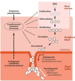
• angiogenesis: new vessels sprout from pre-existing blood vessels or, in the case of intussusception, the lumen of an existing blood vessel splits to form two separate vessels;
• vasculogenesis: new blood vessels are formed by recruited endothelial cells
differentiated from endothelial progenitor cells (EPCs).
In order to develop and establish a functional vascularization, a variety of approaches are currently used.
The use of scaffolds alone made with angiogenic biomaterials can be used to recruit endogenous cells to vascularize the scaffold in situ. This is a simple, cost effective and versatile method of inducing angiogenesis, exploiting the vascular response induced by inflammation during scaffold implantation.
Decellularized scaffolds have been also used to provide a natural template for recre-ating the vascular network.
Current approaches to therapeutic angiogenesis focus on the angiogenic growth fac-tor released from biomaterial scaffolds, permitting a localized and sustained delivery of these molecules. The challenge in this case consists in controlling the right deliv-ery rate profile of more growth factors and in using the proper dose of each one of them [121].
Scaffolds can be also used to deliver specific cells (i.e cells transfected with genes that allow over-expression of angiogenic factors).
Figure 1.4: Neovascularization encompasses both angiogenesis and vasculogenesis. Angiogenesis represents the classic paradigm for new vessel growth, as mature, differentiated endothelial cells form sprouts from parental vessels. Vasculogenesis involves participation of endothelial progenitor cells that, recruited, form new blood vessels. Images adapted from Isner at al.[2].
objectives
2.1 Thesis rationale
In the previous chapter, the skeletal system and the key role of ECM were in-troduced. Then, it was described with particular attention the leading strategies employed today and the issues remained open in the field of bone healing and regen-eration. Finally, the principles of tissue engineering were defined, focusing on how their application can potentially overcome the limits of the current treatments for bone defects.
The final objectives of the presented research work were the production and the evaluation of scaffolds for bone regeneration.
Starting from the concept of biomimicry a multicomponent scaffold to regenerate
bone was design. We hypothesized to be more efficient to try mimicking the ECM
template that characterized the early step of the bone healing process, rather than the final bone tissue. In this way the normal regeneration progression would be supported by scaffolds able to support cells and to trigger their response in a phys-iologic way. The reference ECM chosen was therefore the one present in the soft callus and not the final mineralized matrix.
Contemporary, the research focused on the evaluation of the cell response to the scaffold properties. We decided to modify scaffold features and to investigate care-fully the type I collagen network production and assembling because it represents the natural template for the final mineralization.
Moreover, due to the key role of vessel formation in TE and the correlation between osteoblasts and endothelial cells, the influence of the scaffolds on angiogenesis and vascularization was assessed.
morpholo-gies and chemical compositions. The produced constructs were used as model to understand the strict relation between cell behavior, scaffold properties and ECM production/assembling.
In the next sections materials, structures and setups used are introduced and de-scribed.
2.1.1 Sca
ff
old fabrication
2.1.1.1 Materials
In this work scaffolds were produced using two polymers: one from synthetic origin, poly-d,l-lactic acid (PdlLA), and one from natural origin, silk fibroin (SF).
PdlLA
Poly-d,l-lactic acid is a aliphatic polyester. This is a very interesting category of synthetic polymer because of their good mechanical properties, tailorability and controlled degradation rate [123, 124, 125]. Due to the chiral nature of lactic acid, two stereoisomeric forms are possible and distinct polymers can be obtained: the two stereoregular polymer PdLA, PlLA, and the PdlLA. Poly-l-lactide (PlLA) is the product resulting from the ring-opening polymerization of l-lactide; it presents
a crystallinity of about 37% with glass transition temperature between 50°C and
80°C and fusion temperature between 180°C and 190°C. Poly-d-lactide (PdLA) is analogous to PlLA but it is derived from polymerization of d-lactide. Poly-d,l-lactide is the racemic polymer obtain from a mixture of d- and l-lactic acids; it has an amorphous structure presenting a glass transition temperature at about 60°C.
Figure 2.1: The two stereoisomeric forms of lactic acid: PdLA and PlLA.
molecules and degradation occurs at higher rate. Differences in crystallinity also influence the mechanical properties with semicrystalline materials characterized by higher performance [126].
The material itself and its degradation products were studied to verify the biocom-patibility and toxicity. Publications report good biocombiocom-patibility results, with only some few inflammatory responses [127]. Among polyester family, PLA is very in-teresting because it is soluble in many different solvents, it is easy to process in different 3D structures and, depending on the process story, it degrades in 2 to 12 months [128].
Poly-d,l-lactic acid (PdlLA, type RESOMER®207, MW= 252 kDa) was purchased
from Boehringer Ingelheim, Germany. The polymer was used without further pu-rification. The two solvent used, dichloromethane (DCM) and dimethylformamide (DMF), were obtained from BDH Chemicals (UK) and J.T.Baker (Holland), respec-tively.
Silk fibroin
The term silk indicates the protein polymers synthesized by epithelial cells in special-ized glands of Arachnids and some Lepidoptera. According to their animal origin, silk proteins differ in composition and final configuration, but some general proper-ties can be identified: their primary structure is usually simple and repetitive, while
the secondary structure is mostly β-sheet because of the predominance of amino
acids with a short lateral chain in hydrophobic domains. These domains allow the
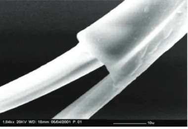
Figure 2.2: Scanning electron micrograph of a partial degummed silk filament.
Silk from Bombyx mori cocoons has been widely utilized as biomaterial. The fibers
have a diameter of 10-25 µm and consist of two inner filaments of fibroin coated
by a layer of sericin, which acts as a glue and represents 25-30% of the whole fiber [130]. A fibroin molecule is made of two protein chains, a light chain (about 26 kDa) and a heavy chain (about 390 kDa) in a ratio 1:1. They are joined by disulfide bonds between two cysteine amino acids and by a glycoprotein called P25 that is non-covalently linked to both fibroin and sericin [129]. Amino acid composition of fibroin from Bombyx mori consists mainly of glycine (43%), alanine (30%) and serine (12%). The heavy chain is formed by 12 domains which compose the crystalline regions of the silk fiber: they are repetitions of sequences Gly-X, where X can be one of the following amino acids: alanine, serine, valine or threonine. As previously indicated, the formation of crystalline structures is due to the short lateral chains of the amino acids in these regions, which allow protein folding in a β-sheet conformation [131]. The secondary structure of the less crystalline portions of the heavy chain is random coil because the bigger lateral chains, which cause a steric effect [129].
Figure 2.3: Typical amino acid sequence of fibroin.
Silk fibroin exists in two different polymorphisms: the glandular state before crys-tallization (Silk I) and the state which follows its extrusion with the formation of
β-sheet secondary structures (Silk II). When fibroin is in a Silk I state, it is water sol-uble and can be easily crystallized by heat or shear stresses. Fibroin can be in a Silk I state also in the aqueous solution obtainedin vitro. After crystallization, β-sheet structures are asymmetric: one side is occupied by the hydrogen atoms of glycine residues, while methyl groups of alanines populate the other side. Strong hydrogen bonds and van der Waals forces form a structure which is thermodynamically stable [129].
peptides which can be phagocytized by cells more easily.
Biocompatibility of this natural polymer has been extensively established. It was observed that silk sutures could elicit hypersensitivity in some cases, but it was demonstrated that the major cause of these responses was sericin. Once sericin is removed by degumming, the biological response of fibroin is comparable to all biomaterials [129, 130].
In addition, silk fibroin has the nature of a multifunctional material which possesses active domains in the linkers among hydrophobic blocks, which can be recognized by cell receptors and demonstrated to stimulate cell adhesion and growth [132].
2.1.1.2 3D structures
Microfabricated scaffold
The microfabrication system, developed and optimized in our laboratories is able to fabricate scaffolding supports of controlled geometry.
The microfabrication system consists of three independent slides (National Instru-ment, Austin, Texas, US), that move a platform where the polymer solution is extruded and the scaffold is built on. The extrusion system is composed by a glass
Figure 2.4: On the left the polymer extrusion from the metal micro-needle. On the right typical microfabricated scaffolds.
syringe fixed up on an automatic pumping system (11 Plus, Harvard Apparatus, Massachusetts, US) by which it is possible to set the proper flow rate; a metal
micro-needle (HamiltonTM, 34 gauge - 60 microns inner diameter; 1 cm length, 90º
point style) is connected to the glass syringe by a luer-lock mechanism.
by layer in the vertical direction. Each layer is composed by a series of parallel fibers, deposited by the syringe through a back-and-forward movement. The distance between the fibers, which influences the properties of the scaffold, is a parameter controlled with the software (LabVIEW). Once a layer is completed, the support moves down, then, another layer is deposited, whose fibers are perpendicular to those of the previous one.
Figure 2.5: Scanning electron microscopy images of PdlLA microfabricated scaf-folds obtained changing polymer solution concentrations.
The process strongly depends on environmental variables (such as temperature and humidity) and parameters such as number of layers, distance between fibers, pressure applied to the syringe, viscosity of the solution, motor speed and dimensions of the needle.
Some examples of PdlLA scaffolds obtained changing some parameters are reported
Fig. 2.5.
Sponge
Sponges are one of the most used scaffolds in bone Tissue Engineering, especially because of their high porosity.
Several techniques can be employed, such as solvent casting particulate leaching (with salt or glucose as porogen) and freeze-drying, which may be eventually com-bined with gas foaming.
Figure 2.6: On the top scanning electron microscopy images of PdlLA sponges.
Scale bars = 100 µm. On the bottom micro-CT color-coded pore diameter scale
images. NaCl particulates with three different dimensional ranges were used: (A)
240-315 µm, (B) 315-425µm, and (C) 425-1180 µm
overnight and washed into distilled water for 3 days to eliminate both the residual solvent and the salt.
The obtained sponges were finally air dried at room temperature Setting the proper combination of process parameters was very important to produce porous, well
in-terconnected and homogeneous scaffolds. Therefore, parameters such as polymer
concentration, NaCl amount and range size were optimized to obtained the specific properties requested each times.
Images of sponges produced varying NaCl range size are shown in Fig. 2.6, while in Fig. 2.7 there are some quantitative data obtained to characterize the same scaffolds. In each chapter there are the specifications of the scaffolds produced.
Sponge with SF fibers
The fibers were obtained from Bombyx mori silkworm cocoons.
Figure 2.7: On the left porosity of the three scaffolds. On the right pore size profile of the three scaffolds.
of these spread fibers was mixed with sieved NaCl particulates, ranging from 425 to 1180µm as before, and the PdlLA solution (see chapter 2.1.1.2.2), obtaining a 1:14 w/w polymer/porogen final concentration. The mixture was air dried (24-36 hours) and immersed in deionized water (dH2O) for 3 days with changes every 6 hours for the removal of the porogen.
The parameters (PdlLA concentration, NaCl and SF fibers amount, porogen range size) were chosen after several attempts, trying to optimize porosity and interconnec-tivity. Images of scaffold with different PdlLA concentration and SF fibers amount are shown in Fig. 2.8.
2.1.2 Cells
In this work three main type of cells were used: MG63, hMSC and HUVEC.
2.1.2.1 MG63
Figure 2.8: Scanning electron microscopy images of PdlLA sponges with SF fibers. The concentration of the initial polymer solution is different as the amount of the SF fibers.
2.1.2.2 hMSC
Human mesenchymal stem cells (hMSC) are multipotent stromal cells with the ability to differentiate into osteoblasts (bone cells), chondrocytes (cartilage cells), adipocytes (fat cells) and neurons (nervous system cells). They were originally iden-tified in the bone marrow stroma, where they regulate key stages of haematopoiesis. MSCs have a great capacity for self-renewal while maintaining their multipotency. The degree to which the culture will differentiate varies among individuals and how differentiation is induced. The capacity of cells to proliferate and differentiate is known to decrease with the age of the donor, as well as the time in culture.
2.1.2.3 HUVEC
model system for the study of the function and pathology of endothelial cells.
2.1.3 Animal model
2.2 Outline and objectives
The skeletal system is unique in its capacity to regenerate after injury through the processes of bone healing.
Factors that influence the repair process, particularly in situations of challenging trauma or disease, include proper biological signals and sufficient vascularization. The regenerative processes of osteogenesis and angiogenesis are strictly linked at both cellular and molecular levels, and the responses of osteoblasts and endothelial cells have been shown to be correlated in vitro.
Despite the knowledge on the bone healing, characterized by different steps, the
evaluation of the cell response at the first stages has not been deeply studied.
The overall objective of this work was therefore to investigate the role of scaffold properties in osteogenesis and angiogenesis. The strategy was to design constructs with the proper morphology and to evaluate the results focusing on the early step of bone healing and not only on the final mineralization. This objective was evaluated in the following specific aims.
CHAPTER 3 - AIM I
Determine the efficiency of different scaffold geometries exploring the relationship
among them and collagen 3D organization.
Two scaffolds, made with the same chemical composition but different 3D architec-ture (a random versus a ordered strucarchitec-tures), were used as model to verify different influence on biological outputs. In particular the analysis of the collagen distribu-tion was performed to evaluate if different morphology lead to different collagen
assembling and organization. The results show that scaffolds with random
poros-ity distribution seem to allow a collagen organization similar to the natural callus matrix.
CHAPTER 4 - AIM II
Evaluate the effects of in vitro scaffold pore size on ECM matrix produced by MG63.
pore size plays an important role in cell behavior and ECM development. Moreover, a strict relation between collagen I assembly and mineralization was demonstrated.
CHAPTER 5 - AIM III
Evaluate angiogenic effects of SF fibers on a PdlLA engineered constructs.
The development of an extracellular matrix in most tissues, including bone, is depen-dent upon the establishment of a well developed vascular supply to provide oxygen and nutrients to regenerating tissues. We hypothesized that incorporation of silk fibroin fibers to a PdlLA sponge enhances the construct capacity to better support endothelial cell colonizationin vitro and to promote in vivo vascularization.
CHAPTER 6 - AIM IV
Evaluate angiogenic and osteogenic response of hMSC in a co-culture model onto
different functionalized engineered constructs.
In vitro studies have shown that endothelial cells regulate the function of osteoblast
on type I collagen development:
a new in vitro evaluation
perspective
1
4.1 Abstract
Bone tissue engineering takes part in the complex process of bone healing by com-bining cells, chemical/physical signals and scaffolds with the scaffolds providing an artificial ECM network. The role of the support template for cell activity is crucial
to guide the healing process. This in vitro study compared three different PdlLA
scaffolds obtained by varying the pore size generated by applying different salt leach-ing processes. The influence of pore dimensions on the ECM matrix produced by
human osteosarcoma-derived osteoblasts (MG63 cell line) seeded on these diff
er-ent materials was analyzed. This work is targeted on the intermediate stage of the bone healing process, where a collagen network is beginning to develop by the growing osteoblasts representing the template for the ultimate stage of bone forma-tion. Imaging analyses assessed by confocal laser microscopy were combined with gene expression measures of the most common genes involved in the bone healing process. Furthermore, in vitro evaluations were carried out to investigate cell mor-phology, proliferation and viability. Results showed that different pore size matrixes
can affect ECM development and that cell organization, collagen I assembly and
mineralization are strictly correlated.
4.2 Introduction
Tissue engineering for bone regeneration is based on developing scaffolds, which
are structural supports able to mimic the native tissue-like environment, and to assist, once combined with cells, a complete healing process. The main idea is to reproduce the natural Extracellulalar matrix (ECM) with scaffolds able to simulate the physiological ECM features and to interact biomolecularly with cells tuning their functions and guiding the entire multicellular events of ECM formation and tissue regeneration [75, 169].
ECM of connective tissues is a fibrous composite that surrounds cells comprising many biological components. It is the main component of bone combining inorganic and organic parts. Osteoblasts are responsible for ECM synthesis and mineraliza-tion. ECM components are central to every phase of wound healing. In the early step, the cellular inflammatory reaction is followed by a fibrocartilage tissue pro-duction (soft callus tissue). This is the natural fingerprint for the formation of hard callus, that is physiologically substituted by the final bone, either cortical or trabec-ular, remodeled and completed in an ultimate stage. During the repair process every newly formed tissue evolves starting from the previous and the entire healing mech-anism results from the development of these overlapped stages [1, 62, 63, 64, 65, 66].
Tissue engineering efforts to create functional biological tissues relies on 3D scaffolds as temporary artificial ECM frameworks [170]. 3D constructs are currently produced by different techniques using biocompatible polymers, either of synthetic or natural origin. Different features can be achieved and have to be taken into account when designing a scaffold for bone tissue reconstruction. Therefore, mechanical properties and geometrical features (pore size, pore morphology and interconnectivity) should be selected considering the mechanisms of biocompatibility described by Williams [78, 171], that is the ability of a material to perform with an appropriate host response during the regenerative phase.
The study demonstrated that a scaffold with a randomly organized structure, rather than an ordered porous matrix, was more favorable as a template for a physiological collagen assembly from a bone tissue regeneration perspective.
Based on this previous study and beginning with a salt leached scaffold
4.3 Materials and Methods
Production of the salt-leached sca
ff
olds
Sponges with randomly distributed pores were produced by solvent casting par-ticulate leaching technique [126, 136, 150]. PdlLA (Resomer R207S, Boehringer Ingelheim Germany) was dissolved in dichloromethane:dimethylformamide (70:30
v/v) to obtain a 7% (w/v) solution. Sieved NaCl particulates with three diff
er-ent dimensional ranges (240-315 µm, construct S1; 315-425 µm, construct S2; and
425-1180µm, construct S3) were mixed into the PdlLA, obtaining a 1:25 w/w
poly-mer/porogen final concentration. The mixture was air dried (24-36 hours) and
immersed in deionized water (dH2O) for 3 days with changes every 6 hours for the
removal of the porogen.
All the scaffolds were prepared with a thickness ranging from 2 up to 3 mm by
casting into glass petri dishes, then, once detached, they were cut into discs with 6 mm diameter. Before use in in vitro cell culture studies, scaffolds were sterilized
with aqueous ethanol solution 70% (v/v) at 4°C for 24 hours and dried under a
sterile hood at room temperature. Scaffold modifications due to the sterilization process were not detected.
Sca
ff
old characterization
Scanning electron microscopy (Supra 40 Zeiss, operating mode: high vacuum, sec-ondary electron detector) was used for the evaluation of scaffold surface morpholo-gies. Samples were previously sputter-coated with a thin