Channel Access over Path Segments for Ultra Low
Latency MANETs
Ram Ramanathan
BBN Technologies Cambridge, MA 02138 Email: [email protected]Fabrice Tchakountio
BBN Technologies Cambridge, MA 02138 Email: [email protected]Abstract—While the capacity of Mobile Ad Hoc Networks
(MANETs) has received considerable attention, the issue of end-to-endlatency has been largely ignored. As military MANETs get larger and denser with an increasing number of end-to-end hops, the latency and jitter experienced by packets will be prohibitively high for existing and emerging real-time applications. We present and study a novel mechanism called CAPS (Channel Access over Path Segments) for reducing end-to-end latency. The key idea behind CAPS is to reserve the floor multiple hops (a path segment) at a time. This is accomplished by using multi-hop RTS and CTS frames that acquire the access rights for an entire segment toward the destination, with virtual carrier sense acting on a path basis. Our architecture also includes acut-through physical layerthat pipelines a bit stream through the receive and transmit chains. We present a numerical analysis of the relative performance gain from our ideas, complemented by a simulation-based analysis. Our study shows that, depending upon the parameters used, a 3x to 8x reduction in latency over current systems is possible.
I. INTRODUCTION
In a mobile ad hoc network (MANET)1 a packet typically travels over several hops enroute to the final destination. Each hop consists of receiving the packet, processing it, queueing it, deciding the next hop, re-contending for the channel and finally retransmitting the packet. Thus, the packet experiences a number of delays at each hop: the per-hop transmission delay, the processing delay, the channel access delay and the propagation delay. While the sum of these delays is not a problem for small-diameter networks, they are significant enough to pose a serious problem to scaling a MANET to a large number of hops.
We believe that future military MANETs are increasingly likely to be characterized by a large hop diameter. Our belief is based on two trends – 1) increasing number of nodes due to increasing coverage demands and decreasing radio costs; and 2) shorter (range) hops. The latter is in turn due to a number of factors. First, higher capacity (data rate) implies a higher frequency band because that is where more spectrum is available. How-ever, propagation characteristics are poorer at higher frequencies, implying short ranges. Second, higher data rates are obtained by higher-order modulation schemes (more bits per symbol) which require higher SNR, which in turn point to short ranges. Thus, increasing network size and shortening communication
Partially supported by DARPA grant HR0011-05-C-0123 1-4244-1513-06/07/$25.00 Copyright 2007 IEEE
1The term is used here to mean peer-peer, self-organizing, wireless, possibly
mobile, multihop networks, and broadly includesmesh networks,sensor networks
andmilitary packet radio networks
ranges foretell MANETs with very large diameters. Indeed, an architecture where dense low-cost relays self-form into a topology consisting of short-range high-data-rate links is emerging as a blueprint for next generation military MANETs, and for example, is integral to the DARPA WAND program [1].
Limiting the end-to-end latency and jitter is of paramount importance in a number of real-time applications such as high-definition interactive video, packetized voice, real-time imag-ing, and advanced distributed virtual-reality applications such as telemedicine. In order for these applications to seamlessly extend to military MANETs, we need to provide comparable latency and jitter performance – something possible today only with small MANETs. While the capacity challenges of these applications over MANETs have been much researched, the latency challenges remain largely unsolved.
We present a novel access protocol called CAPS – Channel Access over Path Segments. CAPS reserves the channel multiple hops (called asegment) at a time, briefly as follows. A Segment Request-To-Send (S-RTS), originated by the source is multihop relayed until it encounters an existing flow, at which point the segment is terminated and a Segment Clear-To-Send (S-CTS) completes the reservation and creates path-based NAV state in nodes neighboring the segment. Packets departing the source are switched at the physical layer, without re-contention, through the segment. A new segment is initiated, if required, in the same manner after the existing flow completes. Thus, contention for the channel in CAPS only happens at the beginning of a new segment, not at every hop. Channel access even with the most sophisticated mechanism has an inherent inefficiency due to the dynamic and distributed nature of the problem. With CAPS this inefficiency gets multiplied only by the number of segments in the path (which could be as low as 1), rather than the number of hops - a big difference. Due to small timescale in which the segment handshake happens, CAPS supports mobility of nodes.
We analyze the performance of our proposed design in two ways. We present a numerical analysis of the latency reduction using CAPS over a cut-through physical layer. Using the exact packet sizes from our design, we derive an expression for the latency reduction factor vis-a-vis 802.11, and observe upto 8x reduction in latency for typical operating parameters. We also present a simulation-based study of the latency reduction using
we observe significant gains (3.5x to 8x depending upon the network parameters).
II. SYSTEMDESCRIPTION
In this section, we describe a system architecture and layering concept for ultra-low-latency packet transport in MANETs within which CAPS is intended to operate.
A node in our system consists of a single transmitter and a single receiver, each consisting of the RF front-end and modem functions. These are independently and quickly tunable to one out of 4 frequency channels that are mutually orthogonal, that is, cause negligible co-channel interference2. Thus, full-duplex op-eration (transmitting on one channel while receiving on another) is possible.
Packets go from a source s to a destination d in units of
segments. A segment (r0,rt) is a sequence of nodes r0,r1, r2, ... , rt,t >0, such that at each relay noderi,1< i < t, a data
packet is cut-through switched at the physical layer. A segment is the basic unit of channel access, that is, a packet secures the right to traverse the entire segment before leaving the source of a segment.
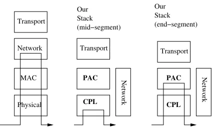
Figure 1 illustrates the layers in our proposed system. The physical and medium access control layers in the conventional stack (Fig. 1(left)) are enhanced to acut-through physical layer (CPL) and a path access control (PAC), respectively. The CPL can perform cut-through switching of data packets, and the PAC reserves the channel to enable this. Thus, peer PAC layers at the two ends of a segment (r0 and rt) communicate to implement
the segment (Fig. 1(right)). The PAC layers in the intermediate relay nodes are not involved in the transport of a data packet over a segment(Fig. 1(middle)). We shall refer to the node at which a segment begins (e.g.r0) as theSegment Start Node (SSN) and the node at which a segment ends (e.g.rt) asSegment End
Node (SEN). Note that unlike conventional architectures where the packet has to go up three layers and down three layers at each hop, our system only involves the physical layer most of the time, and even at SENs requires going up only two layers. When a segment is terminated, the packet goes up to PAC layer which initiates a new segment.
A number of protocols are possible at each of the PAC and CPL layers. The main topic of this paper, namely CAPS, is a contention-based protocol at the PAC layer. It requires certain “services” from the CPL layer, but is not dependent upon the precise details of its working. The service assumptions, over and above a typical conventional physical layer, are as follows.
1) The PAC must be able to set the transmitter and receiver independently to a frequency of its choice.
2) The CPL should provide two modes: pipelined, in which a received packet is transmitted cut-through and the PAC never sees it; and non-pipelined in which the CPL hands PAC the packet.
3) In pipelined mode, the CPL header contains the end desti-nation and next hop fields.
2This requires sufficient separation between the channels. This may be difficult
in lower bands (e.g. the 2.4 GHz) but possible in higher bands (e.g in 5.8 GHz). This is even easier to accomplish with multi-band radios where channels could be in different bands altogether.
Our Conventional
Stack
Stack (mid−segment)
Physical MAC Network Transport
Transport
Network
PAC
Stack (end−segment)
Network
Transport
PAC
CPL CPL
Our
Fig. 1. Conventional layering and data path (left), our layering in the intermediate nodes (middle), and our layering at segment ends (right).
4) The CPL can store a “floor state” set by the PAC. It can only retransmit if the floor state is not busy.
The CPL is described in detail in [2]. In this paper, we focus on the PAC layer, and describe one possible solution, namely CAPS, which extends the 802.11 protocol to a path oriented regime (note that extending TDMA is another entirely valid solution to PAC). The description assumes services from CPL as discussed above. While each of CAPS and CPL have some merit and utility on their own, it is their combination that allows the dramatic order-of-magnitude reductions that were argued for in section I. CPL requires CAPS to have reserved the channel for the outgoing stream in order to pipeline the bit stream. CAPS can run on conventional physical layers, but the system soon hits the latency bottleneck of packet transmission time per hop. Thus, we consider CAPS and CPL jointly for the remainder of the paper.
III. CAPS: OPERATION ANDANALYSIS
CAPS is an extension of the traditional CSMA/CA mechanism to a segment-oriented regime. That is, everything that happened over a hop – control packets, floor reservation, error detection, re-contention – now happens over a path segment. Recall that CSMA/CA consists of a Request-To-Send (RTS), Clear-To-Send (CTS), DATA, and ACK handshake between the sender and receiver over one hop. Nodes that hear the RTS and CTS defer using a Node Allocation Vector (NAV), thereby enabling the communicating pair to acquire the floor for the duration of the handshake. In CAPS, the handshake occurs between the Segment Start Node (SSN) and the Segment End Node (SEN), with the intermediate nodes behaving merely as “re-energizers” of the packet by performing cut-through relaying. In the case of a single-segment path, the SSN is the packet source (originator) and the SEN is the packet end-destination. We shall refer to the control packets in CAPS as S-RTS, S-CTS, and S-ACK (indicating “segment RTS”, “segment CTS” etc). An additional packet S-TRM (Segment Termination) is used for terminating segments (see below).
S-CTS, S-TRM and S-ACK. The other three channels are DATA channels. The use of multiple DATA channels is to allow the CPL to perform cut-through forwarding of DATA along the segment as will be explained later. The control packets are all relayed using the non-pipelined mode of the CPL whereas the DATA packets use the pipelined mode. When idle, nodes are tuned to the control channel.
The packet formats for S-RTS, S-CTS, S-ACK and S-TRM are shown in [2]. We shall use their sizes in the forthcoming analysis.
We now describe the operation of CAPS in terms of the steps involved in sending a packet form a sourceS to a destinationD
in a connected network.
1) S becomes the Segment Start Node (SSN) and initiates a segment.
2) The SSN sends an S-RTS with a configured “maximum segment”, initializes hop count to zero, and sets the relay and source addresses to its address. It includes the desti-nation and next hop (R) in the CPL header. The S-RTS is transmitted on the control channel.
3) Node R processes the S-RTS in non-pipeline mode as follows. If the hop count is within the maximum segment size, and the floor state is not BUSY, it does the following:
• Increment the hop count in the S-RTS.
• Replace the relay address field in the S-RTS withR
• Retransmit the S-RTS by giving it to the CPL.
Otherwise, it terminates this segment. It constructs an S-TRM packet with the TA set to this node (R) and RA equal to the relay address field. Thus, the S-TRM is addressed to the previous hop on the path.
4) Nodes other than R that receive the S-RTS process it as follows. They set their floor state to BUSY. These nodes are called sentinels for the S-D flow as they protect that flow by refusing to forward other S-RTS’s.
5) The S-RTS continues to be relayed until it either reaches the destination, the maximum segment length is exceeded, or it hits a busy node. In the first two cases the current node becomes theSegment End Node(SEN) and the last case the previous hop is made the SEN by virtue of the S-TRM. 6) The SEN constructs an S-CTS with itself as the source
address, and puts the SSN as the destination in the CPL. It also enters the Duration field asLs∗(TSctsh +TSackh )+TSdatah
whereLs is the length of the current segment, taken from
the hop count field of the S-RTS, and TSctsh , TSdatah and
Th
Sack are the per hop delays of the S-CTS, S-DATA and
S-ACK packets respectively. This captures the total duration for which the packet transfer will be ongoing relative to the time at the SEN. It also initializes the frequency index to 0, and tunes its receiver toF0
7) The S-CTS is relayed back to SEN in non-pipelined mode. At each relay node, the transmitter is tuned to the frequency Fi in the received S-CTS, the receiver is
tuned to F(i+1)mod3 and the frequency field is updated to
F(i+1)mod3. We assume that the S-CTS is relayed back
along the same path of relay nodes as the S-RTS3. All nodes receiving the S-CTS set their NAV duration to equal the duration field in the S-CTS.
8) The SSN transmits the DATA which is relayed in the pipelined mode. Each relay uses the transmit and receive frequencies that were set when the S-CTS went back. The DATA contains as the “destination” the SEN and when it reaches the SEN a CRC is performed. If there are more packets in the current burst, the “more fragments” flag in the Frame Control field is set. Sentinels use this information to increment their BUSY durations.
9) If the CRC is successful, an S-ACK is relayed to the SSN. Otherwise, the DATA is silently discarded. The S-ACK is relayed in non-pipeline mode. A node, including a sentinel, receiving the S-ACK changes the floor state to NOT-BUSY. It is also changed to NOT-BUSY after the expiration of the duration timer (this is in case the S-ACK is lost).
10) The SSN either times out and retransmits the same DATA or sends the next DATA in the burst, if any.
11) If the SEN is not equal to the final destination of the packet, it now becomes the SSN. After a random duration after the duration period terminates, it initiates another segment toward the destination (in other words, we start again from step 2).
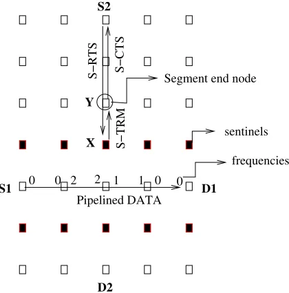
An example of CAPS operation is illustrated in Figure 2 on a Manhattan grid where each node can both interfere and communicate with only its four nearest nodes4. We assume that the transmission time for each hop for control packets is 1 unit and DATA is 10 units. We ignore propagation and all other delays. Suppose there are no flows to begin with. Then, flow 1 is initiated fromS1toD1. The frequencies are set up as shown in the figure. Notice that the frequencies (0,1,2) are assigned in round robin order starting from thedestination, not the source, because it is the S-CTS that is used to assign frequencies. This sets up the sentinel nodes (shown darkened) to have a floor state of BUSY with a duration value of 18 units (refer to Step 6 in the description). Then the DATA starts.
While this is ongoing, flow 2 is initiated from S2 to D2. When the S-RTS for this reaches the sentinel for flow 1, namely node X which has a floor state of BUSY, it responds with an S-TRM (segment terminate) frame. The node Y preceding node X in the path then becomes the segment-end-node, and sends an S-CTS back to S2. Note that the S-RTS and S-TRM do not interfere with the DATA packets from flow 1 since they are on a completely different frequency.
S2 sends the DATA packet (in pipelined mode) to Y. Provided the DATA is received error-free, Y sends an ACK to S2. When flow 1 ends, (S-TRM will contain the duration from node X), flow 2 is re-initiated with Y as segment-start-node. A backoff algorithm is used to ensure that multiple flows waiting for flow 1
3While this is typically the case when symmetric links or shortest hops are
used, it is not a crucial assumption. The S-CTS can be made to “reverse the route” of the RTS by having each relay node pick as the next hop of the S-CTS the previous hop in the path fromStoD, which it can compute using the topology table.
4We recognize that communication range is in general shorter than interference
Segment end node
S−RTS
S−TRM
Pipelined DATA
S−CTS
0 0 2 2 1 1 0 0
frequencies sentinels
X Y
S1
D2
D1 S2
Fig. 2. Example illustrating segment termination and sentinel nodes
to finish do not all start at the same time. Note that the segment needs to terminate not at the sentinel itself but before it because the sentinel’s DATA frequencies may be busy from flow 1 packets. While the description and example have implicitly assumed omni-directional antennas, CAPS accommodates directional an-tennas as well, without any change. For example, if highly directional antennas are used for the pipelined DATA between S1 and D1 in figure 2, the sentinels other than nodes along the path will not exist (assuming S-RTS and S-CTS are sent directionally, as is typical [3]). A crossing flow such as between S2 and D2 can now end one hop further downstream. In general, depending on the beam pattern, some subset of neighboring nodes will be sentinels. The reciprocity property of directional antenna assures that the two flows will not interfere.
Link level error detection and correction is done only at the end of each segment. The SEN sends an ACK if the packet is received without errors, and silently discards the packet if there are uncorrectable errors. However, we note that, independent of link-level error detection and correction at ends of segments, channel coding may be used to allow the receive chain to correct errors at relay nodes without violating cut-through pipelining. If block encoding is used, this functionality may be done as part of the receive chain, still retaining the ability to pipeline (in the granularity of blocks). The number of errors at an SEN will depend upon the segment length and the nature of channel coding, if any, available at the CPL.
CAPS fully supports mobility of nodes, to the same extent that a 802.11 based network does. In both cases, the time scales involved in the transfer of a burst over a segment is typically much smaller than the time scale in which mobility happens. We note that CAPS is not like a “virtual circuit”, “path setup” over MANETs [4], [5], [6], which are network layer techniques that persist for a flow sessionand needs to be kept alive in between bursts making it susceptible to mobility. Rather the segment is closer to a “virtual link” in delay characteristics and has the same
tolerance for mobility as a typical 802.11 link.
A. Latency Reduction Estimates
We now compare the end-to-end latencies for conventional (current) systems and CAPS as a function of the number of hops. We assume that the network is loaded lightly enough that there are no crossing paths, that is, the segment is never terminated due to the existence of another flow. Thus, the length of a segment is bounded solely by the maximum segment length indicated by the source/SSN in the S-RTS packet (see item 2). We recognize that this is a simplistic assumption but it does provide insight into performance dependence on hop length, segment number and burst size using the exact packet format numbers – allowing us to determine whether or not the additional bits are worth it5. Multiple flows are considered in the simulation analysis presented in IV.
For the conventional numbers we assume that the system has multiple channels, so that intra-path interference does not exist. This allows a fair comparison – otherwise CAPS, which uses multiple channels has an obvious advantage. We ignore the frame handling and turnaround times in both cases but note that this is higher for conventional relaying. Latency is defined as the time between a bit (any bit) leaving the source and arriving at the destination.
Letrbe the data rate in bits/usec,bbe the burst size (number of back-to-back data packets) andhthe number of hops. The end-to-end latency for conventional (802.11 based) relaying is given by
λconv=h
r ·(Srts +Scts +b·(Sdata +Sack)) (1)
where Srts, Scts, Sdataand Sackare the length in bits for
RTS, CTS, DATA and ACK respectively, inclusive of the PLCP (physical layer) header. The PLCP header is 192 bits, the RTS, CTS and ACK frames alone (without the PLCP) are 160 bits, 112 bits, and 112 bits respectively [7]. We assume a 400 byte payload exclusive of all headers6. The RTP/UDP/IP headers amount to 40 bytes, and the 802.11 MAC only header is 34 bytes.
Thus, we have the total sizes in bits (including PLCP) as
Srts = 352, Scts = 304, Sack = 304, Sdata = 3984 (2)
From (2) and (1), the latency for conventional networks is
λconv=h
r ·(656 +b·4288)usec (3)
We now consider end-to-end latency of CAPS with CPL. In this case, an S-RTS, S-CTS and S-ACK travelshhops each in non-pipelined mode. Note that this is irrespective of the number of segments, that is, if there are multiple segments, there are multiple different S-RTS/S-CTS/S-ACK packets that together travelhhops each. The data packet, however, is in pipelined mode except at
5There is indeed rich scope for stochastic analysis of the average segment length
and latency with multiple crossing flows, but is hard enough to merit a paper by itself. The analysis is given here as a useful first step.
6Assuming a real-time voice application going over RTP/UDP/IP/802.11, the
segment-ending nodes. At other nodes, it only incurs the time to receive and process the CPL header.
Let SSrts, SScts, SSdataand SSackbe the per-hop
transmis-sion times for the S-RTS, S-CTS, S-DATA and S-ACK respec-tively, andSropldenote the size of the CPL header, andNsenthe
number of segment end nodes. LetLsbe the maximum segment
length. For simplicity, let us assume thatLsis a factor ofh. Then,
the latency for CAPS in usec is given by (see [2] for details)
λcaps≤ h
r ·(868 +b·676 + h
Ls−1 ·(
900 +b·3616
h )) (4)
The latency reduction factor for CAPS over conventional is thus
Γconv caps =
λconv
λcaps
= 656 +b·4288
868 +b·676 +Lhs−1 ·(900+hb·3616) (5)
Noting that (h/Ls)−1 ≤h/Ls, we can get a conservative
(lower bound) estimate of the latency reduction factor that is independent ofh, as
Γconv caps =
λconv
λcaps ≥
656 +b·4288
868 +b·676 + 900+b·3616 Ls
(6)
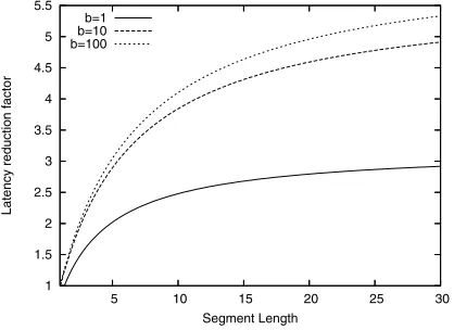
Figure 3 shows a plot against Ls for various values of b. As
expected, CAPS does better when the segment length is longer since a packet can be cut-through switched for a longer time before needing to be fully received. At a segment length of 1, the scheme falls back to the conventional scheme (notably, there is no degradation in performance). At reasonableLs, say 15, there
is a 2.5x to 5x reduction. With multiple flows, this reduction is likely to be even higher. Intuitively, this is because the access inefficiency is higher at higher loads, and while 802.11 magnifies this by the number of hops, CAPS only multiplies it by the number ofsegments. Our simulation results in section IV confirm this intuition.
1 1.5 2 2.5 3 3.5 4 4.5 5 5.5
5 10 15 20 25 30
Latency reduction factor
Segment Length b=1
b=10 b=100
Fig. 3. Latency reduction factor of CAPS over 802.11 as a function of segment length.
A more detailed version of the analysis and other plots may be found in [2].
IV. EXPERIMENTALANALYSIS
We have implemented a simulation model of CAPS and an abstraction of a cut-through physical layer inns-2[8]. To develop our model, we have modified the C++ implementation of the 802.11 module in ns-2. In particular we have implemented two major changes to the source code. The first change is for CAPS and enables multihop support of 802.11 MAC frames. To enable this, we augmented the RTS,CTS,DATA,ACK frames with a target destination field. On the transmission path of the 802.11 MAC, we inserted appropriate hooks to allow the update of relevant frame fields, and to allow access to the forwarding table at each hop. On the reception path, intermediate hops can relay any 802.11 MAC frame while only segment termination nodes can generate CTS and ACK frames.
The second change is for the CPL in which pipelining of frame bits occurs. In our model, when the first bit of frame is detected by the WirelessPHY module, the entire frame is retrieved and forwarded after a delay equivalent to the time to pipeline the packet. This is approximated by the time to transmit the CAPS and CPL headers. A two-orthogonal-channel model (one channel for control traffic and another for data) has been added to support CPL7 All frames are transmitted based on information contained in the transit table. The transit table is an array (indexed by source and destination) of keep/relay/discard enumerations and is populated based on information learnt through 802.11 frames and/or the forwarding table. For carrier sensing to work effectively in our environment, the NAV duration has been set to a function of the number of hops and transmit times of the S-RTS and DATA frames.
An instance of a multihop wireless mesh network is created by placing a set of N2 nodes in a N x N square area. Nodes are stationary8 and are placed in a Manhattan grid. Routes among nodes are statically configured with the help of a NO Ad-Hoc Routing Agent (NOAH) [9]. In all our experiments, we assume a channel rate of 11Mbps for both 802.11 and CAPS. For traffic generation, a fraction p of all nodes are selected randomly to be sources of traffic while nodes, not too close from sources, are picked randomly as destinations. Each source can generate CBR traffic at a rate of R packets per second. To speed up simulations, we use longer packets instead of many packets. Packet sizes varied between 8 Kbits (base size) to 32 Kbits (represents 4 back-to-back packets). This abstractly models packet burst transmissions within RTS/CTS round trips. Each simulation lasts S seconds. A traffic session starts at a time uniformly distributed between 1 and(S−2D)seconds and lasts for a duration uniformly distributed around D seconds (namely [0.8D,1.2D]).
A. CAPS Performance
We now analyze the performance of CAPS versus that of 802.11 as a function of the network size and the offered load. In all our experiments, the rateRwas set to 1 packet/sec, the mean
7Because of the abstract way we model the pipelining, two channels are
sufficient (one for data and one for control).
8We note that CAPS works for mobile networks, but since the relevant
duration D to 50 seconds, and the simulation duration was 200 seconds9. Each data point is averaged over 5 randomly-seeded runs. Due to space constraints, we only present comparative results on the end-to-end latency, which is the time taken for a packet to go from its source to its destination, averaged over all flows. In all cases considered, the packet delivery rate was 100 %.
0 10 20 30 40 50 60 70 80 90 100
5 10 15 20 25 30 35 40 45 50
Latency (milliseconds)
Number of Hops CAPS vs 802.11/CSMA (1 flow)
CAPS 802.11
Fig. 4. Single flow (one source to one destination), relay-oriented PHY.
Figure 4 depicts the latency as a function of the number of hops for a single traffic flow (no contention). This preliminary simulation is to confirm and show the correspondence between our theoretical and simulation-based models. We see a linear relationship between latency and hops as predicted in section III-A (equation 4). CAPS outperforms 802.11 by at least a factor of 4. This result confirms our analysis.
10 15 20 25 30 35
6 8 10 12 14 16 18 20
Latency (milliseconds)
N (mesh of NxN) Latency vs N, p=12%, burst = 1pkt
CAPS 802.11
Fig. 5. Multiple flows, 1 pkt/burst, p = 12
Figures 5 - 8 depict the latency as a function of the side of a Manhattan grid, with multiple traffic flows, and for different combinations of the offered load (p) and the number of packets per burst. We use the side N of a Manhattan grid because it is hard to control precisely the number of hops in randomly generated flows. However, the number of hops should be roughly proportional toN. Recall thatpis the number of nodes randomly selected as sources of a traffic flow.
9Values of these parameters were chosen mainly for their simplicity.
0 50 100 150 200 250 300 350 400 450
6 8 10 12 14 16 18 20
Latency (milliseconds)
N (mesh of NxN) Latency vs N, p=12%, burst = 32pkts
CAPS 802.11
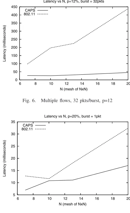
Fig. 6. Multiple flows, 32 pkts/burst, p=12
5 10 15 20 25 30 35
6 8 10 12 14 16 18 20
Latency (milliseconds)
N (mesh of NxN) Latency vs N, p=20%, burst = 1pkt
CAPS 802.11
Fig. 7. Multiple flows 1 pkt/burst, p=20
Figure 5 shows the latency withp= 12% and a single packet per burst. The latency of CAPS remains nearly constant while that of 802.11 increases linearly. The initial drop is likely due to an artifact of our traffic flow generation process: the number of flows is proportional to the number of nodes and so a 7x7 network has fewer flows than a 13x13 network. This may cause statistical variability as well as getting unlucky in terms of congestion.
In Figure 6, the burst size is 32 packets, and there is a significantly larger gap in the latency. This is because CAPS
0 50 100 150 200 250 300 350 400 450
6 8 10 12 14 16 18 20
Latency (milliseconds)
N (mesh of NxN) Latency vs N, p=20%, burst = 32pkts
CAPS 802.11
reservation is amortized over a larger number of packets whereas each packet costs more in 802.11. ForN = 20, there is a factor of 8.5x reduction in latency.
Figures 7, 8 depict the latency performance for a higher offered load (p= 20%). Once again, there is a factor of about 2x decrease
at 1 pkt/burst and about 8x in the case of 32 pkts/burst.
Considering the relative latency performance from the above figures for the range of likely typical load/burst profile, a summary CAPS outperformance factor is between 3.5x and 8x depending upon the number of hops. It might be higher still if we increase the number of hops, but unfortunately the high fidelity nature of our simulations resulted in prohibitively large run times for larger grids. Gains are higher with smaller number of higher-rate flows than with a larger number of lower-rate flows.
V. RELATEDWORK
Medium access control in ad hoc network has been a much-studied topic. There are too many works to cite and discuss, but a survey, classification and numerous references can be found in [10]. Most of these techniques are per hop techniques in the sense that packet has to re-contend all over again after being relayed one hop, due to which the latency is proportional to the number of hops. In contrast, CAPS acquires the channel for multiple hops at a time so that the latency is proportional to the number of segmentswhich could be as low as 1.
Physical layer cut-through switching in wired networks (called cut-through routing or wormhole routing) have been well-studied [11], [12]. In cut-through routing, packets entering a network node on one interface are forwarded, without storing, on another interface. Although the basic idea is similar, the problem is vastly different in ad hoc networks, chiefly due to thebroadcast nature
of communications and the resultant need for access control. Further, transmission and reception require a number of steps in waveform processing, and node mobility requires dynamic switching.
In the context of mobile ad hoc wireless networks, there exists work on “label switching” at the medium access or link layer [13], [14] which pushes the forwarding function one layer down. In [13], access time is reduced by having the ACK for a packet double up as an RTS for the next hop. Our architecture involves a more fundamental change compared to these works – switching is done not at the MAC but the physical layer, and floor acquisition is done for multiple hops at a time. A “multi-hop RTS” concept is proposed in [15], but for the completely different problem of antenna pointing. The multi-hop RTS we describe is different in function and operation. Path setup/teardown techniques abound in the literature [4], [6], [5], but are significantly different in that they are network layer techniques that still use a hop-oriented MAC whereas CAPS is at the MAC layer.
Finally, [16] investigates latency reduction using path based access, along with cooperative diversity, as one of the corner-stones of the next generation MANET architecture. However, the proposals there are at quite a high level and do not represent a solution to the problem.
VI. CONCLUDINGREMARKS
We described CAPS, a protocol for channel access over path segments that extends the hop-oriented RTS/CTS/DATA/ACK
handshake to a path-segment-oriented regime. Along with a cut-through physical layer (CPL), CAPS enables data packets to be switched with very low latency within a segment, dramatically reducing overall end-to-end latency. Our analysis shows that the CAPS reduces the end-to-end latency by more than a factor of 4x. Using ns-2, we have conducted experiments on an abstract model of the ROPL and CAPS on a Manhattan grid topology with random streams of traffic. Our simulations show a gain of 3.5x to 8x in latency over conventional hop-oriented networking based on 802.11.
A number of exciting research directions exist, both in the general area of latency reduction and specifically on advancing CAPS. An obvious one is to reduce the gap between access and usage in CAPS which negatively impacts network capacity. TDMA-oriented path access control is another promising but unexplored direction. The concept of adaptively controlling the segment length based on error and other characteristics is a chal-lenging but fruitful topic. More sophisticated theoretical analysis using stochastic techniques is needed for a fuller understanding of the limitations and tradeoffs. Finally, implementing the CPL and CAPS into a prototype testbed, either using conventional hard-ware or a softhard-ware radio is necessary to complete the validation of this concept.
REFERENCES
[1] http://www.darpa.mil/sto/solicitations/WAND/index.html
[2] R. Ramanathan, F. Tchakountio, “Ultra Low Latency MANETs”, BBN Technical Memorandum No. TM-2023, available at http://www.ir.bbn.com/ ramanath/pdf/ull-techreport.pdf
[3] R. Ramanathan, J. Redi, C. Santivanez, D. Wiggins, S. Polit, “Ad Hoc Networking with Directional Antennas: A Complete System Solution,”IEEE
Journal on Selected Areas in Communications, Vol. 23, No. 3, Mar. 2005,
pages 496-506.
[4] S. Ramanathan, M. Steenstrup, “Hierarchically-organized, Multihop Mobile Networks for Multimedia Support”, ACM/Baltzer Mobile Networks and
Applications, Vol. 3, No. 1, pp 101-119.
[5] C. Zhu, M.S. Corson, “QoS Routing for Mobile Ad Hoc Networks,”Proc.
IEEE Infocom, 2003.
[6] G-S. Ahn, A. T. Campbell, S-B. Lee, and X. Zhang, “INSIGNIA,” Internet Draft, draft-ietf-manet-insignia-01.txt, Oct. 1999.
[7] M.S. Gast, “A Definitive Guide”, O’Reilly and Associates, April 2002. [8] The Network Simulator, NS-2. http://www.isi.edu/nsnam/ns.
[9] NO AdHoc Routing Agent (NOAH). http://icapeople.epfl.ch/widmer/uwb/ns-2/noah/
[10] R. Jurdak, C.V. Lopes, and P. Baldi, “A Survey, Classification and Compar-ative Analysis of Medium Access Control Protocols for Ad Hoc Networks,”
IEEE Communications Surveys, Vol. 6, No. 1, First Quarter 2004.
[11] P. Kermani and L. Kleinrock, “Virtual Cut-through: A New Computer Communication Switching Technique”, Computer Networks, 3(3):267–286, September 1979.
[12] E. Leonardi, F. Neri, M. Gerla, P. Palnati, “Congestion Control in Asyn-chronous High-Speed Wormhole Routing Networks”,IEEE Communications
Magazine, Nov. 1996.
[13] A. Acharya, A. Misra, and S. Bansal, “A Label-switching Packet Forwarding Architecture for Multi-hop Wireless LANs,”IBM Tech. Rep., 2002. [14] D. Raguin, M. Kubisch, H. Karl, A. Wolisz, “Queue-Driven Cut-through
Medium Access in Wireless Ad Hoc Networks” IEEE Wireless
Communi-cations and Networking Conference (WCNC), Atlanta, Georgia, USA, March
2000
[15] R.R. Choudhary, X. Yang, R. Ramanathan, N. Vaidya, “On Designing MAC Protocols for Wireless Networks using Directional Antennas,”IEEE
Transactions on Mobile Computing, May 2006.