Deformation Design Method Based on SBF Model
https://doi. org/10.3991/ijoe. v14i03. 8417
Qinzhou Niu!!"#$Yi Liu
Guilin University of Technology, Guilin, China
niuqinzhou@126. com
Abstract—The structure-behavior-function model is a kind of concept sign model and we apply it to the deformation design mainly to express the de-sign concept and dede-sign process. In this paper, the SBF model is used to express a complete design experience knowledge and is used as a node for design rea-soning. We also add the non-axiomatic logic and a calculation algorithm of se-mantic similarity to the SBF model to accomplish the process of deformation design. Finally, turbine blade is taken as an example to prove that the method can realize the deformation designing of parts. Meanwhile, non-axiomatic logic which is able to reduce the repetitive work of the designers is an effective way to simplify the designing.
Keywords—structure-behavior-function, non-axiomatic logic, deformation de-sign
1
Introduction
The deformation design is a comprehensive practical design method which extracts the main variable parameters from the local feature structure, as well as modifies its values of dimension, with the preservation of the basic functions of the product and a small change of the working principle, in order to meet the different needs of the users, and improve the response speed for the market. Deformation design is divided into two types i.e. the deformed of the geometric dimensions and the restructuring deformed of the overall structure. The deformation of the geometric dimensions is the change of the parameters of individual parts , but the structural characteristics of the product is not affected. But based on the individual needs of customers, the restructur-ing deformed of the overall structure changes the type of parts or the number of com-ponents. This deformation will usually change overall structure. Therefore, the de-formation design includes both the conceptual design and the detailed design.
Through external functions, an extended SBF model allows the designer to master the objects which are associated with the designed part in various life cycle.
The combination of artificial intelligence and design theory is a direction of design theory. The non-axiomatic logic(NAL)[3-4]which is an intelligent reasoning method can be applied to conceptual design and innovative design. A brief introduction of it is presented here. Non-axiom logic is a term logic and it has the following characteris-tics: 1)Term logic is a kind of syllogistic reasoning. Each proposition is in the form of the "subject, copula, predicate". The term here refers to a certain concept that can be represented by the name of the concept, while the copula can be interpreted as "is" or "associated with". 2)The specific reasoning form is that two propositions that have a term in common are known, which can be used to produce the third proposition (i. e. the conclusion).
The remainder of the paper is organized as follows. In section two, we introduce the SBF ontology model which is used to indicate design knowledge. Section three introduces non-axiomatic logic model of the deformation designing. The fourth sec-tion describes the semantic calculasec-tion of deformasec-tion design reasoning. In secsec-tion five, through an examples, the concrete realization of the deformation design theory proposed in this paper is discussed. Section six introduces a deformed design system. Section seven is conclusion.
2
Model of SBF Ontology Representation of Deformed Design
Knowledge
2.1 SBF model
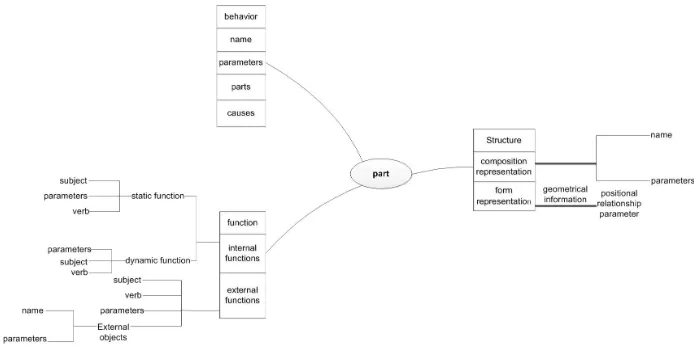
Structure. Structure refers to the appearance of the product, and is divided into composition representation and form representation. The composition representation describes what parts are included in the product and their parameters. Each part in the composition representation can be illustrated by <name, parameters>. Name describes the name of the part, and the parameter is the physical attribute. In order to support the detailed design, the original SBF model is expanded to include form representa-tion. The form representation describes the geometrical information of the part by the positional relationship parameter between the features.
Behavior. The behavior of a part refers to the change of its own state in its life cy-cle, such as the movement of the workbench. The original SBF model only considers the behavior that intend to achieve the desired function, but the extended SBF model also includes the behavior of a part in a variety of life cycles such as machining. An-other difference is that the extended SBF model uses quantitative methods to repre-sent the degree of change in state. The behavior can be reprerepre-sented quantitatively by four elements <name, parts, parameters, causes>. Name represents the name of a behavior. The part refers to which part the behavior belongs to, and the parameter intend to quantify the change of state. Cause is a object which stimulates the current behavior.
Function. The traditional SBF model only considers the relationship between input and output. In extended SBF model, the function is defined as an expected relation-ship between a part (subject) and another part (object) in any life cycle. The concept of function here is more like affordance.
Function can be divided into internal functions and external functions. An internal function means that the subject and the object belong to one product, and the internal functions can be further divided into static and dynamic functions. In static functions, objects are often treated as static parts. For example, the workbench has the function of carrying the workpiece. The workpiece can be seen as a static object. A static func-tion can be expressed as three elements <subject, verb, parameters>. The verb is used to describe the functional relationship. Dynamic function is concerned with the change of dynamic behavior of the object , and a dynamic function can be expressed with three elements <subject, verb, parameters>.
Fig. 1. An structure-behavior-function model
3
Non-axiomatic Logic Modeling of Deformation Design
Process
In this paper, select reasoning rule of NAL as the main reasoning form of the de-formation design, because NAL provides us with not only deduction, induction, ab-duction and other reasoning methods but their formula of true value. These can com-pletely meet our needs in the deformation design. Another important feature of NAL which distinguishes it from other reasoning systems is that reasoning can be done with insufficient knowledge and resources. When it is used to answer questions raised by existing knowledge , these knowledge can be uncertain and incomplete. So every knowledge in the system is only correct to some extent, and each piece of knowledge can be revised according to new knowledge[3]. On the basis of the original NAL model, we have not only improved its terms, but also introduced an algorithm for confidence c. Because the original non-axiomatic logic does not explicitly put for-ward the algorithm of confidence, it only estimates confidence empirically. After the addition of the computational model, the accuracy of the true value which base on both a quantitative calculations and a empirical estimate is greatly increased. We use the true value to assess the deformation process. A deformation with a higher true value represents a higher degree of reliability, and a deformation only with a lower true value represents that the deformation requires further verification. For the sake of convenience, we use nodes to stand for a design implementation of the object.
3.1 A Brief Introduction to Non-axiomatic Logic
lan-guage, the general proposition is composed of subject, predicate, the inheritance rela-tion, and the true value:
S
!
P <f, c>Where S denotes the subject. P denotes the predicate.
!
represents the inher-itance, and <f, c> denotes the true value of the proposition. The proposition indicates that S is the specificity of P and P is the generalization of S. True value of the propo-sition is represented by a number pairs <f, c>. f is the frequency that represents the proportion of successful evidence in all available evidence. c is the confidence, con-sidering the evidence that the system has now and in the future. Proposition with true value is the complete reasoning, and the proposition without true value can only be a logical guess. NAL is described as an inheritance relationship. We can treat each term as a node, and the proposition is the concrete relationship between the two nodes, while corresponding truth value is the strength of the relationship. The reasoning in the logic is expressed in form of a syllogism. A pair of statements are given. If they share a common term, then the conclusion between the other two terms can be derived from the reasoning.deduction M
!
P <f1, c1> abduction P!
M <f1, c1> S!
M <f2, c2> S!
M <f2, c2> S!
P <f, c> S!
P <f, c>Induction M
!
P <f1, c1> M!
S <f2, c2> S!
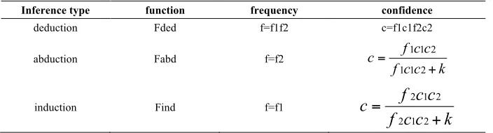
P <f, c>Table 1. A summary of basic syllogistic rules
Inference type function frequency confidence
deduction Fded f=f1f2 c=f1c1f2c2
abduction Fabd f=f2
k c c f
c c f c
+ =
2 1 1
2 1 1
induction Find f=f1
k
c
c
f
c
c
f
c
+
=
2 1 2
2 1 2
4
Semantic Computation of Deformed Design Reasoning
4.1 Calculation method of f
Frequency f:f is the proportion of the successful deformed. NAL has an experi-ence-grounded semantics. That is to say the determination of frequency needs to base on multiple experiments. In fact, a lot of design is difficult to obtain the existing ex-perimental data, because the design work itself may be entirely new. To solve this problem, for those that can not find knowledge of the design, the real frequency can be replaced by a mean value which is estimated by a certain number of experts.
4.2 The calculation algorithm of confidence c
Ontology coding. In order to complete the deformation between the two CAD models, we describe two different concepts with the product semantic expression language (PSRL) to determine whether two different CAD models are semantically similar[6]. The advantage of this approach is that the semantics of the CAD model can be clearly expressed. This can help us to compare the semantic similarities of these models. Note that the ontology here refers to the concept of the term mentioned above. For example, suppose that the 11th stage rotational blade of a turbine is a data ontology, and the sub-last one is another data ontology. The PSRL for the functions of the two ontology is described below.
function
!
11th rotational blade!!
internal function (dynamic function (subject!
rotational blade!verb!
rotate!functional parameter!
10000rpm) !static function (subject!
rotational blade!functional relation!
reaction degree!functional parameter!
0.23)) !=!
external function (subject!
rotational blade!verb(efficiency!relative velocity)!functional parameter (efficiency!
0.9085!relative velocity!
360 m/s)!external objects (name
!
steam))function
!
sub-last stage rotational blade!!
internal function (dynamic function (subject!
rotational blade!verb!
rotate!functional parameter!
10000rpm) !static function (subject!
rotational blade!functional relation!
reaction degree!functional parameter!
0.4)) !=!
external function (subject!
rotational blade!verb(efficiency!relative velocity)!functional parameter (efficiency!
0.8962!relative velocity!
480 m/s) !external objects (name!
steam))With the reasoning mechanism PSRL, we can see that their description is very sim-ilar. In order to achieve the transformation between the two models, we want to quan-tify the semantic similarity between them. In recent years, a lot of measure methods have been put forward to solve this issue. In this paper we have chosen Abdul-Ghafour’s method[7], which is a attribute-based approach. Specifically, the semantic similarity of two concept can be aggregated as a weighed sum of the similarity of their function, behavior and structure. Let C1, C2 as a concept pair. SimG(C1, C2) is
of C1 and C2 . SimJ (C1, C2)is the structure similarity of C1 and C2. Then semantic
similarity of C1, C2 can be defined as:
Sim (C1, C2) =w1SimG (C1, C2) +w2SimX (C1, C2) +w3SimJ (C1, C2) (1)
Where w1, w2, w3 is the weights, and , w1+w2+w3=1. This paper chooses Petrakis’s
method which is one of the attribute-based similarity measure to calculate the contri-bution components SimG (C1, C2) , SimX (C1, C2) and SimJ (C1, C2) .
Simsynsets/glosses(C1, C2)=|S(C1)S(C2)|/|S(C1)S(C2)| (2)
Where S (C1), S (C2) are the attribute sets of concepts C1 and C2, respectively.
The weight of the similarity calculation. This section will describe a calculation method of weights. For the sake of generality, the n contribution components f1 (C1,
C2), f2 (C1, C2) . . . fn (C1, C2) are taken into account in the similarities of C1 and C2.
w1, w2, w3 . . . wn are the weights of f1 (C1, C2), f2 (C1, C2) . . . fn (C1, C2)
respec-tively. And
0
!
w
1,
w
2,
w
3....
w
n!
1
, w1+w2+w3. . . wn=1. Then the overall semantic similarity can be expressed as:Sim (C1, C2) =w1f1(C1, C2)+w2f2(C1, C2). . . +wnfn(C1, C2) (3)
In general, the Pearson correlation coefficient can be used to evaluate the actual similarities and calculated similarities of a certain number of sample pairs. The higher the correlation coefficient is, the better the accuracy of the calculated similarities are[8]. It is difficult to obtain the actual similarity of a sample pair, since the similari-ty is a kind of subjective judgment of human. The actual similarisimilari-ty also need to be replaced by a mean value which is estimated by a certain number of experts. Accord-ing to the above description, we intend to calculate a group of weights that can max-imize the Pearson correlation coefficient. The specific algorithm is as follows, let N be the number of concept pairs whose semantic similarity need to be measured. Ai
(Ci1, Ci2) is the actual semantic similarity of the i-th concept pair. U=[fi1(Ci1, Ci2),
fi2(Ci1, Ci2). . . fin(Ci1, Ci2)]T is a vector. V=[Ai (Ci1, Ci2)]T is a vector. W=[w1, w2,
w3. . . wn]T is also a vector. Then the Pearson correlation coefficient between
actu-al similarity and cactu-alculated similarity can be expressed as:
Corr(WTU, V)= cov( , ) cov( , )
) , cov(
V V w U U w
V U w T
T
=
!
!
!
VV UU T
UV T
w w
w
(4)
Where cov is covariance, and cov(U, U)=UU, cov(U, V)=UV, cov(V, V)=
VV are the following matrices respectively:
! ! ! ! ! ! " # $ $ $ $ $ $ % & )) C (C f ), C (C ))...cov(f C (C f ), C (C f cov( ), ) C (C f ), C (C f cov( . . . . . . . . . )) C (C f ), C (C ))...cov(f C (C f ), C (C f cov( ), ) C (C f ), C (C f cov( i2 i1 in i2 i1 in i2 i1 i2 i2 i1 i1 i2 i1 in i2 i1 in i2 i1 in i2 i1 i1 i2 i1 i2 i2 i1 i1 i2 i1 i1 i2 i1 i1 (5) (6) (7) To solve the w that can maximize corr(wTU, V), we use canonical correlation
anal-ysis method[9]. The conclusion is that w is the eigenvector of the largest eigenvalue of the matrix UU-1UVVV-1VU.
WhereVV=
[
cov(
A
i(C
i1C
i2),
f
i1(C
i1C
i2)
)...
cov(
A
i(C
i1C
i2),
f
in(C
i1C
i2))
]
(8) However, the element of w is not the final result of the calculation. Because some elements may be less than 0, and the sum of remaining elements( greater than 0 ) usually not equal to 1. The final weight is solved by the following standardized meth-od:Let p=(p1, p2. . . pn) is the result of canonical correlation analysis method and
w=[w1, w2. . . wn]T is the final weights. For all pl<0, let pl=0 and wl=0, then
wl=pl/(p1+p2. . . pn)
5
Example of Deformed
We use the 11th stage, the sub-last stage , the last stage rotational blade of a steam turbine as an example to illustrate how to use the above method specifically. In the actual design of bowed and twisted turbine blades, the versatility should be taken into account. It is very helpful to use the type of blade that the factory has been used. Be-cause the workload of designing a bowed and twisted blade is very large, especially the last stage blade is more difficult. The design of a long blade often cost years, so it is an effective way to truncate or lengthen blade to meet the requirement of the design on the basis of the existing blade[10].
The initial work is that two concept pairs are composed of 11th stage, the sub-last stage and the sub-last stage , the last stage. We use y1, y2, y3 stand for the 11th stage,
the sub-last stage , the last stage rotational blade , respectively. Therefore, we have got two concept pairs(y1, y2), (y2, y3) . The specific calculation algorithm is divided
First, we should obtain the frequency f and actual semantic similarity of the two sample pairs. As mentioned before, the real frequency value and actual semantic simi-larity will be replaced by a mean value which is estimated by a certain number of experts. Specifically, six teachers and 30 students who have the knowledge of the design for the blade are invited to carry out this assessment. These teachers and stu-dents judge each concept pair on a scale 0, 0.1, 0.2 . . . 1. And then the three highest ones and three lowest ones are removed, so that we get the mean value of the remain-ing 30 ones. The results is f1=0.8125 , A1=0.76 and f2=0.9331 , A2=0.9267
The second step is to calculate the semantic similarity of the function, behavior and structure of the concept pairs. These three similarities can all be calculated by Petrakis's method. For example, with the functional description of (y1, y2) which is
mentioned above, we can calculate the semantic similarity . S(y1)S(y2)=16, S(y1)
S(y2)=22, based on expression(2)SimG (y1, y2) =0.7272. Similarly, Simx (y1, y2)
=0.6470.SimJ (y1, y2) =0.5238
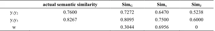
Third, calculate the value of the weights and the semantic similarity of the concep-tual pairs which is the value of confidence. The results are shown in the following table.
Table 2. semantic similarities of function, behavior and structure, the value of weights actual semantic similarity SimG Simx SimJ
y1y2 0.7600 0.7272 0.6470 0.5238
y2y3 0.8267 0.8095 0.7500 0.6000
w 0.3044 0.6956 0
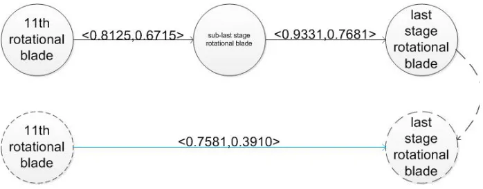
According to the weights and semantic similarity based on expression (1), we can get c (y1, y2) =0.6715, c (y2, y3) =0.7681. In the non-axiomatic design logic, we can
express the above deformation process as a graph.
Fig. 2. An example of propositions
Fig. 3. A deductive deformation design reasoning
6
Conclusion
In this paper, the non-axiom logic is applied to the deformation design , and the blades of steam turbine are taken as an example to prove that this method is feasible. The main innovation is that the SBF model and an algorithm for confidence are added to the non-axiom logic which effectively improves the accuracy of true value of the non-axiom logic. The method can achieve a quantitative assessment of the defor-mation process. With insufficient knowledge , the goals of getting rid of the heavy repetitive work of conventional design and making the product more innovative have been realized. In the process of practical application of NAL , we also found some characteristics of this theory.
7
Acknowledgment
Funding supported by National natrual Science Foundation of China (No 51365010).
8
References
[1]Bhatta, S. R. , & Goel, A. K. (1997). A functional theory of design patterns. International Joint Conference on Artifical Intelligence (Vol. 55, pp. 294-300). Morgan Kaufmann Pub-lishers Inc.
[2]Prabhakar S, Goel A K. (1998). Functional modeling for enabling adaptive design of de-vices for new environments. Artificial Intelligence in Engineering, 12(4):417-444. https://doi.org/10.1016/S0954-1810(98)00003-X
[3]Wang, P. (2011). Rigid Flexibility: The Logic of Intelligence. Springer Publishing Com-pany, Incorporated.
[5]Chen Y, Huang J, Xie Y, et al. (2013) Modeling detailed design knowledge with the ex-tended structure–behavior–function model. Artificial Intelligence for Engineering Design Analysis & Manufacturing, 27(4):415-420. https://doi.org/10.1017/S0890060413000164 [6]Patil, L. , Dutta, D. , & Sriram, R. (2005). Ontology-based exchange of product data
se-mantics. IEEE Transactions on Automation Science & Engineering, 2(3): 213-225. https://doi.org/10.1109/TASE.2005.849087
[7]Abdul-Ghafour, S. , Ghodous, P. , Shariat, B. , Perna, E. , & Khosrowshahi, F. (2014). Semantic interoperability of knowledge in feature-based cad models. Computer-Aided De-sign, 56(11):45-57. https://doi.org/10.1016/j.cad.2014.06.001
[8]Lu W, Qin Y, Qi Q, et al (2016). Selecting a semantic similarity measure for concepts in two different CAD model data ontologies[J]. Advanced Engineering Informatics, 30(3):449-466. https://doi.org/10.1016/j.aei.2016.06.001
[9]Härdle, W. K. , & Hlávka, Z. (2012). Canonical correlation analysis. Journal of Financial Economic Policy, 6(2):179-196. https://doi.org/10.1007/978-3-642-17229-8_15
[10]Shi Zhoudao. (1990) . Turbine Design Basics. Beijing: China Machine Press, pp. 90
9
Authors
Qinzhou Niu is a professor of college of Information Science and Technology in the Guilin University of Technology. He mainly works in the area of manufacturing informatization and artificial intelligence.
Yi Liu is with the College of Mechanical and Control Engineering, Guilin Univer-sity of Technology, Guilin, China.