International Journal of Electronics Communication and Computer Engineering
Volume 2, Issue 1, ISSN (Online): 2249–071X, ISSN (Print): 2278–4209
Adaptive Modem for a Software Defined Radio System
at its Front End
D. VinothVenkatesh, Assistant Professor
Department of Electronics and Communication Engineering, Latha Mathavan Engineering College, Kidaripatti ,Madurai
Abstract - Software defined radio (SDR) is the future Trend
for mobile communication design. As, the hardware Merges into software gradually in communication system, SDR is supposed to facilitate high-speed multimedia Application for future mobile standards. SDR is flexible Reconfigurable and multi-standard system, which is Capable of providing efficient communication. An adaptive Modem forms an integral part of SDR system with robust and high data rate capability. Our project proposes the design and development of a module namely the Adaptive modem for the SDR system using LabVIEW as the tool. This project accomplishes performance analysis of Adaptive Modulation scheme in changing channel conditions. The various modulation schemes analyzed for adaptive modem are BPSK, 16 Quadrature Amplitude Modulation (QAM) and 64 QAM.
Keywords - Software Defined radio, Adaptive modem,
Labview
I. INTRODUCTION
The term SDR signifies that the same hardware architecture can be programmed or reconfigured to cope with any radio standard. The major application of SDR will be in mobile communication transceivers, generic cellular base stations and military radio systems. Realization of SDR will increase the potential to rapidly develop and introduce new value-added services and revenue streams with increased flexibility of spectrum management and usage for mobile network operators. Adaptive modulation is an important component of software radio Adaptive modulation is a way to improve the tradeoff between spectral efficiency and bit error rate. . Multimedia service requires high data rate and good QOS (Quality of Service) as well, therefore adaptive modulation suits well for fulfilling its requirement. A software-defined radio consists of a programmable communication system where functional changes can be made by merely updating software. In this paper, a software-defined radio 16-QAM (Quadrature Amplitude Modulation) modem system is implemented. Radios built using SDR concepts offer Standard architecture for a wide range of communications products non-restrictive wireless roaming for consumers by extending the capabilities of current and emerging commercial air-interface standards Uniform communication across commercial, civil, federal and military organizations potential for significant life-cycle cost reductions over the air downloads of new features and services as well as software patches advanced networking capabilities to allow truly “portable”networks. SDR-enabled devices (handhelds) and equipment (network) can be
dynamically programmed in software to reconfigure the characteristics of the hardware. This is achieved through the use of a set of clearly defined APIs residing on top of a flexible hardware layer. There are three key benefits to a software radio: Performance, Stability, and Flexibility Software implementations of digital base band processing have traditionally been used in digital radio and data applications such as telephone modems, cable modems, wireless data modems and mobile phones (using digital modulation schemes such as PSK, MSK, QAM, GMSK and GFSK). An area still often overlooked is that of implemented with ease in software radio and deliver a level of performance that is close to perfection. By using digital filters in the final IF of a system one can, for example, obtain a pass band with very steep skirts, a tightly controlled group delay or built-in equalization. Digital implementations of IF and baseband processes are free from all sources o drift. Besides enabling levels of performance that were previously eliminating the need for post-assembly alignment or adjustment. With the recent advent of software-defined radio [1], wireless communication systems have become applicable solutions to a wider range of challenging applications. However, wireless communication standards require different computational complexities as shown in table 1 [2].
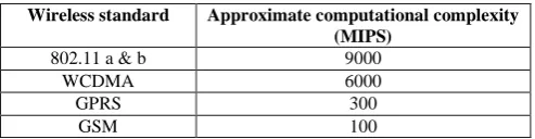
Table 1 computational complexity of some wireless Communication standards
Wireless standard Approximate computational complexity (MIPS)
802.11 a & b 9000
WCDMA 6000
GPRS 300
GSM 100
International Journal of Electronics Communication and Computer Engineering
Volume 2, Issue 1, ISSN (Online): 2249–071X, ISSN (Print): 2278–4209
available in the market for development and testing of SDR systems. For example, the Sundance’s SMT8096
Development platform is equipped with an ADC/DAC (analog-to-digital converter), a Texas Instruments TMS320C6416 DSP as a baseband processor, and an FPGA for pre- and post signal processing [9]. Knowledge of VHDL and DSP programming is required to use the SMT8096 platform. Here, the software implementation of the QAM modem system is accomplished using Labview as a time-efficient and cost effective solution. Labview is a graphical programming environment developed by National Instruments which allows high-level or system-level design via its flow-charting intuitive block-based programming as compared to the commonly used text-based programming languages. A design using LabVIEW is achieved by integrating different blocks, components or subsystems, called Virtual Instruments (VI), within a graphical framework [10-11].
II. ADAPTIVE MODEM
The main concept of adaptive modulation is to maintain a Constant performance by varying transmitted power level, modulation scheme, coding rate or any combination of these schemes. This allows us to vary the data rate without sacrificing BER performance. In a wireless network, because the communication environment varies continually, it is necessary to adapt to fluctuations in the communication environment while communication is in progress (the Adaptive Modulation Technique).In simple words, adaptive modem is an intelligent communication
discussed later. A known bit sequence of length 10 is used as the frame marker. This frame marker is chosen to carry low correlation with PN sequences.
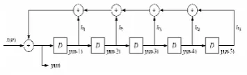
Figure 1: PN generation with linear feedback shift register.
Pulse shape filter
The generated message sequences are passed through a raised cosine FIR filter to create a band-limited baseband signal. The excess bandwidth beyond the Nyquist frequency is specified by a roll-off factor of the filter. In our implementation, a roll-off factor of 0.5 is used.
QAM modulator
The output of the raised cosine filter is then used to build a complex envelope of a QAM signal expressed where ck indicates a complex message, made up of two real messages ak and bk and ck= ak+jbk. After modulating S(t) with ejwt the transmitted QAM signal, s(t) can be expressed as shown in equation (2) .Transmitting two signals by modulating them with QAM, where the transmitted signal will be of the form as shown in equation (3)
^ technique which adapts itself to prevailing channel
conditions to deliver best possible performance.
S (t) =Re[S (t) eiwt] (2)
III.SOFTWARE DEFINED RADIO: QAM MODEM
The building blocks of the QAM modem system are stated in receiver. The first three modules (message source, pulse shape filter, and QAM modulator) make up the transmitter part and the other modules make up the receiver part. A brief description of each block follows. Message source Pseudo Noise (PN) sequences are used for this purpose. A PN sequence is generated with a 5-stage linear feedback shift register structure, see Figure 1, whose connection polynomial
S (t) = I (t) cos2fo (t) +Q (t) sin2fo (t) (3)
At the receiver, these two modulating signals can be demodulated using a coherent demodulator. Such a receiver multiplies the received signal separately with both a cosine and sine signal to produce the received estimates of I(t) and Q(t) respectively. Because of the orthogonality property of the carrier signals, it is possible to detect the modulating signals independently
R(t) =1/2 I(t)[1+ cos(4f (t))]+ 1/2 Q(t) sin(4f (t)) (4)
is given by
H (D) =1+D2+D5 (1)
o o
Hilbert transform
Where D denotes delay and the summations represent modulo 2 additions. The sequence generated via Eq. (1) has a period of 31(=25-1).Two PN sequence generators are used in order to create the message sequences for both the in-phase and quadrature phase components. In the constellation QAM, the reference signals are located at each quadrant. Frame marker bits are inserted in front of the generated PN sequences. This is done for frame synchronization which is
International Journal of Electronics Communication and Computer Engineering
Volume 2, Issue 1, ISSN (Online): 2249–071X, ISSN (Print): 2278–4209
following equation (6).
R(NT)= r(NT)+j r(NT) (5)
U(t)=U(t)+I U(t) (6)
Decision Based Carrier Tracking
Now we examine the phase offset denoted by, between the transmitter and the receiver. Based on this offset, the received signal can be written as where cn indicates the output of a slicer mapping a received sample to the nearest ideal reference in the signal constellation. As a result, the base band error at the receiver and the phase convergence is given by the equations below
R(NT)= r(NT)e-jwnT (7)
E(NT)= cs-r (NT) (8)
Cn= (n-1) +k(n) (9)
Pulse Shaping Filter
If we denote the Channel response as h(f) then the condition for ISI free response is given by
H(nTs)= [1: n=0 and 0; n≠0] (10)
IV.IMPLEMENTATION OF THE QAM MODEM
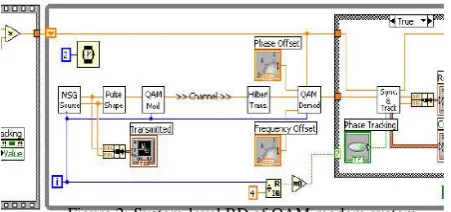
This section presents the LABVIEW software implementation of the QAM modem system. A Labview program consists of two major components: Front Panel (FP) and Block Diagram (BD). A Front Panel provides a graphical user interface while a Block Diagram contains building blocks of a system resembling a flowchart. Labview blocks are called Virtual Instruments, or VIs. The interested reader is referred to [10-11] for details on Labview programming. A system-level BD of the QAM modem is shown in Figure 2.
for this purpose. Frame marker bits are inserted in front of these sequences to achieve frame synchronization. The generated samples are oversampled 4 times according to the specification of the pulse shape filter. This is done by comparing with 0 the remainder of a global counter. Thus, out of four executions of this VI, one message sample (frame marker bit or PN sample) is generated. For the remaining three executions of the VI, zero samples get generated. The total length of the message for one period of a PN sequence and frame marker bits is 164, which is obtained by 4 (oversampling rate) × [10 (frame marker bits) + 31 (period of PN sequence)]. A constant array of 10 complex numbers is used to specify the marker bits. The real parts of the complex values are used as the frame marker bits of the in-phase samples and the imaginary parts as the frame marker bits of the quadrature-phase samples. The PN Generator VI, shown as an icon in Figure 3, generates a pseudo-noise sequence of length 31 by XORing the values of the second and fifth shift registers.
4.2 Pulse shape filter: Next, the generated samples are passed through a pulse shape filter. A raised cosine filter is used to serve as the pulse shape filter. An FIR filter (FIR Filter Ptbypt VI) is utilized for this purpose. The two outputs of the pulse shape filter are combined to construct the complex value pulse shaped message signal. The filter coefficients can be obtained by any filter design tool such as Labview DFD toolkit and stored in an array of constants. The output of the pulse shape filter is illustrated in Figure 3. As shown in the figure, the digital sequence is smoothed or filtered to minimize any inter symbol interference (ISI).
4.3 Modulator:
Figure 3: pulse shape filter
Figure 2: System-level BD of QAM modem system. An overview description regarding the implementation of each block follows.
4.1 QAM Transmitter
Message source: The first component of the QAM modem is the message source. Here, PN sequences are used
The signal passed through the pulse shape filter is then connected to the QAM modulator. The QAM modulated signal s (t) is obtained by taking the real part of the pre-envelope signal s (t) +. This is achieved by performing a complex multiplication between the complex input and a complex carrier consisting of a cosine and a sine waveform. QAM Receiver
4.4 Hilbert transformer:
have an integer group delay, an even number, such as 32, is specified as the filter order.
4.5 phase and frequency tracking
The initial phase estimation is achieved using the phase of the complex data at the beginning of the marker bits. Considering that the ideal reference is known for the first bit of the frame marker, 1 + i in our case.
Figure.4 Phase and Frequency Tracking
This allows us to obtain the phase difference between the ideal reference and the received frame marker bits. The real
and imaginary parts of data at the beginning of the marker bits are also passed to the Phase and Frequency Tracking VI to provide the initial constellation. The sub VI of the frame synchronization is now complete. Note that in order to control the flow of data for the frame synchronization, local variables, shown as a label with two border lines, are used in the Figure5.
V.RESULTS
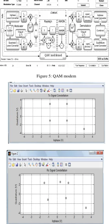
This section provides the simulation study done to test the performance of the SDR modem system. To watch the simulation outcome, a waveform chart and an XY graph are added to the system-level BD shown in Figure 2.If there exist a phase and a frequency offset with no tracking, the received signal appears as shown in Figure 5. As displayed in this figure, the constellation of the received signal is rotated, and the amplitudes of some of the received samples become too small. Obviously, the received signal will change by introducing channel noise. By executing the phase tracking routine, the phase error, affected by the initial phase and frequency difference, is minimized and the received signal becomes a perfect reproduction of the transmitted signal except for the time delay. More specifically, the change in the constellation via the phase and then the frequency tracking can be shown. The constellation of the samples in the I-Q plane becomes that of the ideal reference as the tracking operation progresses. The expected results show that
the developed software-defined radio system provides successful decoding of the transmitted message samples.
Figure 5: QAM modem
Figure 6: QAM constellation: (a) phase offset exists between transmitter/receiver
below shown output shows the theoretical result with the obtained error output, here
environment.
VI.CONCLUSION AND FUTURE WORK
In this proposed paper, QAM based modem is adaptable for the power level changes in various standards. In particular, a 4-QAM-modem system consisting of a message source, a pulse shape filter, a modulator, an automatic gain controller, a Hilbert transformer, demodulator and a phase and frequency tracker was built in the graphical programming environment of LABVIEW. Based on this a 16-QAM modem can be built using LabVIEW system and can be used in the SDR system which can be capable of operating in different
REFERENCES
[1]J. Mitola, The Software Radio Architecture, IEEE communications Magazine, May 1995, 26-38
[2]J.Crocket “DSP architectures for wireless communications”1998
International Symposium on advanced radio technologies
[3] Safadi, M.S.; Ndzi, D.L., "Digital Hardware Choices for Software Radio (SDR) Baseband Implementation," Information and Communication Technologies, ICTTA '06. 2nd, vol.2, no., pp. 2623-2628, 24-28 April 2006 [4] W.H.W.Tuttlebee“Software Defined Radio: Baseband Technologies for 3G Handsets and Basestations”Wiley; 1 edition (March 1, 2004) ISBN-10: 0470867701
[5] S. Tretter, Communication System Design Using DSP Algorithms, Klumer Academic/Plenum Publishers, 2003.
[6] D. Bryan, "QAM for Terrestrial and Cable Transmission", IEEE Trans. Consumer Electronics, vol. 41, no. 3, pp.383-391, 1995.
[7] G. Karam, K. Maalej, V. Paxal, and H. Sari, "Variable Symbol-rate Demodulators for Cable and Satellite TV
Broadcasting," IEEE Trans. Broadcasting, vol. 42, no.2, 1996, pp. 102-109. [8] L. D'Lunaetal., "A Single-chip Universal Cable Set-top Box/Modem Transceiver," IEEE Journal of Solid-State
Circuits, vol. 34, no. 11, 1999, pp. 1647-1660.
[9] Sundance, Software Defined Radio Development Platform.
http://focus.ti.com/lit/ml/sprt348a/sprt348a.pdf
[10] N. Kehtarnavaz and N. Kim, Digital Signal Processing System-Level Design Using LabVIEW, Elsevier, 2005.
[11] National Instruments, LabVIEW User Manual, Part Number 320999E-01, 2003.
[12] N. Kehtarnavaz and C. Gope,“DSPSystem Design Using Labview and Simulink: A Comparative Evaluation,”
Proceedings of ICASSP, vol. 2, 2006, pp. 985-988.
[13] Sturman, Taj A. Bowyer, Mark D.J. Petfield, Neil R. Astrium Limited, Anchorage Road, Portsmouth, Hampshire, “Skynet 5: MILSATCOM using SDR”, Military Communications Conference, 2007.MILCOM 2007. IEEE, Oct. 2007, on page(s): 1-7.
[14] Wasif. M. Elahi .M. Sanghavi. C. Sch. Of Electr. Sci., VITUniv, Vellore, “Analysis and Implementation of Adaptive Modem for SDR”,
Wireless Communications, Networking and Mobile Computing, 2007. WiCom 2007. International Conference on Sept. 2007, on page(s): 1248-1251.
[15]Globa, L.S. Kurdecha, V.V. Inst. Of Telecomm. Syst., NTUU "KPI",
Kiev “software updating of the mobile