INTRODUCTION
Adhesion is in the literature [1] defined as the ability of mutual adhesion of two contact materi-als. Adhesion is a result of attractive forces be-tween the particles of surface layers of two con-tacting different substances. In the transport tech -nology, adhesion means the ability of the trans-port device to transfer the tensile force between the drive wheels and the carriage track.
To define the contact of a rotating drive crane wheel on a steel rail, the adhesion coefficient is used instead of the friction coefficient. The adhe -sion coefficient expresses the ability to transfer tangential forces of the contact surfaces of two different surface roughness without slipping.
The physical nature of adhesion has not yet been satisfactorily explained. The original idea that the microscopic unevenness of the wheel and rail surfaces acts as gearing, has long since been abandoned, as the precision and finely machined crane wheels have higher adhesion values than the roughly machined wheels.
Travelling cylindrical or conical drive wheels of the crane are made of steel or cast iron. For cranes and crane trolleys, the torque must always be brought to two opposite wheels from the drive. There are two basic ways of arranging the drive of the drive wheels of the cranes - individual and central. The central drive uses one drive unit where the engine torque multiplied by the gear ratio is evenly brought to the drive wheels.
The individual drive uses a given number of drive units, equal to the number of drive wheels.
The crane tracks consist of steel rails or stan-dard rolled bars of I, U, HEA, HEB cross sec -tions and the like made of 10 and 11 structural steel classes.
Due to the crane wheel and rail materials used, the friction coefficient between the wheel and the rail has low values, the adhesion weight of the cranes is an important parameter of the cranes. The adhesion weight is the part of the total weight of the crane that acts on the drive wheels, because only these wheels provide the tensile force through friction.
Volume 13, Issue 2, June 2019, pages 92–99
https://doi.org/10.12913/22998624/106244
Adhesion Coefficient on the Limit of Slippage at Star-Up
of the Manual Crane Trolley
Leopold Hrabovský
1*, Martin Mantič
2, Věra Voštová
31 VŠB - Technical University of Ostrava, 17. listopadu 2172/15, 708 33 Ostrava - Poruba, Czech Republic 2 Technical Univerzity of Košice, Letná 9, 042 00 Košice, Slovak Republic
3 Czech Technical University in Prague, Jugoslávských partyzánů 1580/3, 160 00 Prague 6 - Dejvice, Czech
Republic
* Corresponding author’s e-mail: leopold.hrabovsky@vsb.cz
ABSTRACT
Cranes are common handling devices used in construction, assembly and engineering plants. Bridge cranes with
a suspended crane trolley (electric or manual operated hoist) are used in almost all engineering and service
opera-tions. The trouble-free operation of these devices depends on many factors; one of the parameters influencing the
operation of crane trolleys (crane trucks) and crane bridges is adhesion. The presented paper describes the
theoreti-cal assumptions, experimental determination and verification of the coefficient of adhesion on the limit of slippage
at starting of the manual crane trolley.
Keywords: coefficient adhesion, crane trolley, hoist, handling device.
Research Journal
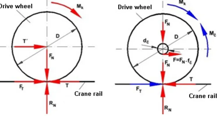
Accepted: 2019.04.26The tensile force on the circumference of the crane drive wheel (acting on the rail) T [N] is in equilibrium with the longitudinal rail response (i.e. the crane wheel tensile force) FT [N]. The ability to produce this fixed line (rail) reaction against the tensile force at the circumference of the drive wheel is called adhesion.
The tensile force on the circumference of the drive crane wheels is not unlimited as, after reach-ing a certain tensile force, the partial drive wheels begin to slip (i.e. rotate significantly faster than the speed of travel) on the surface of the crane rail. This phenomenon occurs when the extent of the longitudinal reaction of the rail drops.
The tensile force on the crane wheel circumfer-ence T [N] can be determined from the relation (1).
(1)
If more than one wheel of the crane trolley is driven by one drive unit, then the tensile force on the circumference “n2” of the drive wheel of the crane T [N] can be expressed according to the relation (1) and the tensile force on the circum-ference of one driven wheel T1 [N] according to the relation (2).
(2)
The tensile force on the circumference of the wheel T [N] is limited by the conditions of adhesion (the state of the rolling surfaces, the presence of pollutants, the wheel load and the dynamic balance of drive, etc.) and must meet the inequation (3).
Tmax ≤ Ft = FN ∙ μmax[N] (3)
The highest tensile force on the circumfer-ence of the travelling drive wheel, which is not yet slipped, is called the tensile force on the adhe-sion limit FTadh [N], see (4).
FTadh = RN ∙ μ [N] (4)
where RN [N] - axial force (rail reaction), μ [-] - adhesion coefficient.
The value of the adhesion factor is influenced by a number of factors, particularly weather con-ditions and the condition of the rail contact sur-faces and the drive crane wheel.
In terms of the tensile strength of adhesion, the extent of the adhesion coefficient at low speeds is the most important, where the crane trolleys have the greatest tensile force and therefore the great-est risk of slippage.
EXPERIMENTAL STATION
The device for determining the adhesion coefficient on the limit of slippage of the man -ual suspended crane trolley, see Fig. 2, consists of two basic parts [3]. The first is represented by the own crane trolley 1, the second by the fixed crane track (rolled profile I 140) 2, on which the crane trolley 1 (forward or reverse movement, exerted by the manual force of the operator) travels.
The suspended crane trolley 1 is fitted with four cast iron conical travel wheels 3, two of which are driven 3b and two drives 3a.
The drive travelling wheels 3a are mounted on the right cross member 4 of the crane trolley 1. On the circumference of the driving wheels 3a there is a gearing with straight teeth (number of teeth z = 36). The right cross member 4 consists of two axially symmetrical parts, left 5 and right 6. Both the drive travelling wheels 3a (with an internal hub diameter of 28 mm) are fitted with play on the wheel axis 7, which passes through the holes in the left 5 and right 6 part of the right cross member 4. The lock ring for the shafts 8 prevents the travelling wheel 3 from sliding out of the wheel axis 7.
The driven travelling wheels 3b are mounted on the left cross member 9 of the crane trolley 1. The left cross member 9 is also formed by two axially symmetrical parts, the left 10 and the right 11. Both the driven travelling wheels 3b are fit -ted with play on the wheel axis 7, which passes through the holes in the left 10 and the right 11 part of the left cross member 9. The lock ring for the shafts 8 prevents the travelling wheel 3b from sliding out from the wheel axis 7.
A hole is created in the right side 6 of the right cross member 4, into which the outer cylindrical surface of the pinion hub 12 is inserted. The pin-ion hub 12 is provided with three holes (8.5 mm diameter), by means of which the pinion hub 12 is attached to the outer surface of the right side 6 of the right cross member 4 with the bolts 13.
The pinion shaft 19 is inserted into the hole of the pinion hub 12. Against sliding out from the pinion shaft 19, a groove is created at a certain
distance from the pinion shaft end 19, to which the lock ring 17 is placed.
In the face of the pinion shaft 19 a hole with in -ternal thread is created. An ex-ternal threaded part of the prism 18, onto which a washer 15 and a spring washer 16 are previously mounted, is screwed into the internal thread of the pinion shaft 19.
An internal hole of the torque sensor 20 is in-serted onto the prism 18. The torque sensor 20 has an internally threaded hole (6 mm depth) on its shell at the end. The bolt shank 21, on which the washer 22 is mounted, is threaded through the hole in the holder 23. The threaded part of the bolt 21 is threaded into the hole with M4 internal thread into the torque sensor 20, thereby prevent-ing movement around the torque sensor axis 20. Fig. 2. The device for determining the adhesion coefficient on the limit of slippage of the manual suspended
crane trolley
A hole is created in the other end of the holder 23 through which the bolt shank 25 is threaded, which then passes through the holes (6.2 mm di-ameter, distance from the longitudinal axis of the torque sensor 20 is 51.25 mm) created in the left 5 and right 6 parts of the right cross member 4. The washer 26 is placed under the head of the bolt 25. The washer 26, the spring washer 27 and the nut 28 are mounted on the threaded part of the bolt 25 extending from the hole in the left part 5 of the right cross member 4.
Holes are created in the two cross members 4 and 9 through which the pins of the suspension bar 29 are threaded. The washers 30 are thread-ed onto the pins on the outside of both the cross members 4 and 9. The split pins 31 prevent slid-ing the suspension bar 29 out from both the cross members 4 and 9.
Holes are created in the two cross members 4 and 9, through which the threaded rod 35 is threaded, which defines the distance between the two inner surfaces - the right part 11 of the left cross member 9 and the left part 5 of the right cross member 4 of the cross members 4 and 9 by means of the nuts 34, the washers 33 and the spring washers 32.
The two longer arms of the sensor holder 37 are slid over onto both the threaded rods 34. The arms are placed into a desired (precisely defined)
position by means of washers 33, spring washers 32 and nuts 34. The two longer arms of the sensor holder 37 are provided with two holes. The two arms of the sensor holder 37 are connected in one unit on one side by the shorter arm. Two holes are created on the shorter arm of the sensor holder 37. The bolts 40 are threaded through these holes, the spring washers 27 and the washers 26 are slid onto their shanks. The bolt shanks 40 extending from the holes of the shorter arm of the sensor holder 37 are provided with the washers 26 and the threaded parts of the bolts 40 are screwed into the internal threads at the top of the load sensor 36.
Two holes are drilled on the lower flange of the rolled profile I 140 2 (crane track). The short -er arm of the holding plate 41 is attached to the lower surface of the crane track 1, in which two holes are created. The bolts 39 are inserted into the holes from the underside of the holding plate 41, on which the spring washers 27 and the wash-ers 26 are mounted. The bolt shanks 39 then pass through the opposite holes (from the underside of the lower flange) of the rolled profile I 140 2. The washers 38, the washers 26, the spring washers 27 and the nuts 28 are gradually mounted on the threaded parts of the bolts 39 extending on the upper surfaces of the lower flange of the rolled profile I 140 2. The holding plate 41 is connected to the crane track 2 in a mutually demountable manner with this bolt connection.
Two holes are created in the longer arm of the holding plate 41 in its lower part. The bolts 40 are threaded through these holes and they are fitted with the spring washers 27 and washers 26. The bolt shanks 40 extending from the holes of the longer arm of the holding plate 41 are provided with the washers 26 and the threaded parts of the bolts 40 are screwed into M6 internal threads in the lower part of the load sensor 36. The hold-ing plate 41 is connected to the crane trolley 1 in a mutually demountable manner with this this threaded connection.
EXPERIMENTAL DETERMINATION OF
ADHESION COEFFICIENT ON THE LIMIT
OF SLIPPAGE AT STARTING OF THE
CRANE TROLLEY
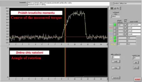
The effect of the resulting torque (from the weight of the load on the lever arm) produces the tensile force T [N] on the circumference of the drive crane wheels [4]. It is assumed according to Chapter 2 “Theory of Transmis-sion of Tensile Force through AdheTransmis-sion” that this force is in balance with an adhesion force FT [N]. At some point, due to the increase in torque Mk2 [N. m] the drive crane wheels slip on the rail. The moment of slippage as well as the torque Mk1 [N. m] according to Fig. 3 is recorded by a tensometric torque sensor and a rotation angle sensor. The torque increase and the angle of rotation of the driving pinion of the drive wheels of the crane truck are read by means of a measuring card. The course of both read quantities is graphically represented in a measurement program created in LabWiew (see Fig. 4).
At the moment of the slippage of the drive crane wheel on the rail, its angle of rotation, which is capable of being detected by the sensor (due to the installed perforated disk which is fixed to the measuring rotor and the two optical sen-sor mounted on the stator), as the perforated disk moving simultaneously with the rotor interrupts the light of the fork optical sensor by its group of holes and bridges [5]. The resulting light intensity changes are converted into voltage pulses by the phototransistors, the number of which (90 holes) is a measure of the rotation angle that are record-ed in the measurement program graph through the measurement card.
The crane trolley is gradually loaded in the centre of gravity with a load of the known weight m [kg], over the weight mz [kg]. Due to the sym-metry of the seating of the travelling wheels, it is possible to calculate the adhesion weight of the FN [N] of the drive wheels acting on the crane rail according to the relation (5).
FN = mN∙ g = = (mk + m + mz) ∙ g [N] (5)
where: mN [kg] - the adhesion weight of the crane truck acting on the drive wheel, n - the number of all traveling wheels, n1 - the number of non-driven crane wheels. The total torque Mk [N. m], see Fig. 3, on the circumference of the drive wheels can be calculat-ed according to the relation (6), providcalculat-ed that the losses in the geared transmission are neglected.
Mk =Mk1∙ i = Mk1∙ [Nm] (6)
where: i - gear ratio, z2 - number of teeth of the drive pinion, z1 - number of teeth on the circumference of the drive crane wheel.
Fig. 5. The model of the device for determining the adhesion coefficient on the limit of slippage of the suspended
Fig. 3 shows that the torque on the circumfer-ence of one drive crane wheel Mk2 [N. m], gains the value, see (7).
[Nm] (7)
The value of the adhesion coefficient on the limit of slippage of the suspended crane truck can be calculated according to the relation (8).
[-] (8)
where fč [-] - arm journal friction coefficient (for sliding seating fč = 0,07 ÷ 0,1); R [m] - ra-dius of the crane wheel; rč [m] - pin radius of the crane wheel seating; FN [N] - the adhesive weight of the crane wheel acting on the crane rail, see the relation (5). The derived relation (8) results from the mo-ment equation (9), see Fig. 1, for the axis of the drive travelling wheel.
∑ M = 0: Mk - Mč - FT ∙ R = 0 (9)
where Mč [N. m] - journal friction moment, ac-cording to Fig. 1 it gains the value, see the relation (10).
Mč = FN∙ fč∙rč[Nm] (10) The torque value Mk1 [Nm] is read from the graphical record, see Fig. 4, at the moment of the drive wheel pinion rotation, corresponding to the beginning of the slippage of the drive wheels on the rail (shown by the displacement of the line by 1 pulse in the “y” axis direction), see bottom of Fig. 4).
The torque Mk [N. m] on the circumference of the drive wheels is calculated:
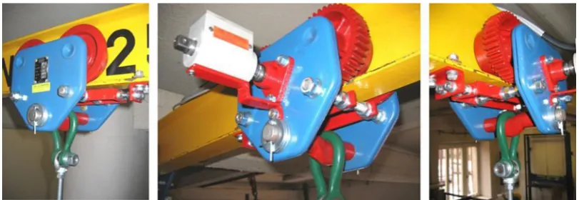
a) according to the relation (6), with the known value of Mk1 [N. m] (gained from the measure-ment from the record see Fig. 4), the number of the pinion teeth z1 and the travelling wheel z2. The value is entered in the relation (8), from which the required adhesion coefficient on the limit of slippage at starting of the crane truck µ [-] is calculated [6]. A measuring device model created in SolidWorks 2012 x 64 Edition SP 5.0 is shown in Fig. 5 and Fig. 6 shows an im-Fig. 6. The implemented device for determining the adhesion coefficient on the limit of slippage of the suspend
-ed manual crane trolley
Fig. 7. The model of the device for determining the adhesion coefficient on the limit of slippage of the suspended
plemented device for determining the adhesion coefficient on limit of slippage of the suspend -ed manual crane trolley.
b) according to the relation (3), with the known value of the maximum Mk1 [N. m] (gained by means of the load sensor 36, see Fig. 2), the value of the maximum number of the pinion teeth z1 and the travelling wheel z2.
The model of this version of the measuring device for determining the adhesion coefficient on the limit of slippage of the suspended manual crane trolley created in SolidWorks 2012 x 64 Edition SP 5.0 is shown in Fig. 7.
CONCLUSIONS
The paper describes the design of the measur-ing station, the purpose of which is to determine the adhesion coefficient of the drive wheels on the limit of slippage from the recorded value of the torque applied to the drive pinion and the pinion angle of the manual crane trolley.
In the first version, the adhesion coefficient of the drive wheels of the crane trolley is determined from the maximum torque applied to the drive pin -ion at the beginning of slippage of the drive wheels on the surface of the lower flange of the crane rail.
In the second version, the adhesion coefficient of the drive wheels of the crane trolley is determined
from the maximum value of the sensed tensile force at the beginning of the slippage of the drive wheels on the surface of the lower flange of the crane rail.
The effect of the resulting torque (from the weight of the load on the lever arm) produces the tensile force on the circumference of the drive crane wheels. This force is in balance with an adhesion force. At some point, due to the increase in torque the drive crane wheels slip on the rail. The moment of slippage as well as the torque is recorded by a ten-sometric torque sensor and a rotation angle sensor. The torque increase and the angle of rotation of the driving pinion of the drive wheels of the crane truck are read by means of a measuring card. The course of both read quantities is graphically represented in a measurement program created in LabWiew.
The presented paper in the chapter “Experi -mental Determination of Adhesion Coefficient on the Limit of Slippage at Start-up of the Crane Trolley” also describes the experimental determi -nation of the adhesion coefficient on the limit of slippage at starting of the crane trolley and Table 1 shows the pilot test values.
Acknowledgements
This work has been supported by The Minis-try of Education, Youth and Sports of the Czech Republic from the Specific Research Project SP2019/101.
Table 1. The adhesion coefficient on the limit of slippage at starting of the crane trolley
No. measurement m = 0 kg m = 25 kg m = 50 kg
Mk1 [Nm] Mk
[Nm] [-]µ Mk1 [Nm] [Nm]Mk [-]µ Mk1 [Nm] [Nm]Mk [-]µ
1 0.32 1.013 0.262 0.93 2.945 0.285 1.24 3.927 0.228
2 0.30 0.950 0.244 0.87 2.755 0.264 1.46 3.167 0.273
3 0.34 1.077 0.281 0.89 2.818 0.271 1.37 4.338 0.254
4 0.31 0.982 0.253 0.90 2.850 0.274 1.29 3.167 0.280
5 0.33 1.045 0.271 0.86 2.723 0.261 1.42 4.497 0.265
∑ µi 1.321 ∑ µi 1.355 ∑ µi 1.300
∑ µi/i 0.262 ∑ µi/i 0.271 ∑ µi/i 0.260
No. measurement m = 75 kg m = 100 kg
Mk1 [Nm] Mk
[Nm] [-]µ Mk1 [Nm] [Nm]Mk [-]µ
1 1.95 6.175 0.262 2.19 6.935 0.227
2 1.87 5.922 0.250 2.34 7.410 0.244
3 2.03 6.428 0.274 2.46 7.790 0.258
4 1.99 6.302 0.268 2.27 7.188 0.236
5 1.89 5.982 0.253 2.42 7.663 0.253
∑ µi 1.307 ∑ µi 1.218
REFERENCES
1. Klimecký, O., Veverková H., Bailotti K., Müller,
J.: Manipulace s materiálem. Doprava v lomech.
VŠB-TU Ostrava 1988, pp. 320.
2. Polák, J., Pavliska, J., Slíva, A.: Dopravní a mani-pulační zařízení I. VŠB-TU Ostrava 2001, pp. 104.
3. Hrabovský, L.: The Plant for analyssis coefficient of adhesion of betwen-wheel. Elektronický časopis Perner´s Contacts.
4. Michalik, P., Dobřanský, J., Hrabovský, L., Petruš,
M.: Assessment of the manufacturing
possibil-ity of thin-walled robotic portals for conveyance workplaces. Advances in Science and
Technol-ogy Research Journal. 12(1), 2018, 338-345. DOI: 10.12913/22998624/87063.
5. Hrabovský, L.: Action on Crane Runway Caused by Horizontal Forces due to Crane Skewing. Key Engineering Materials, 669, 2016, 391-399. DOI: 10.4028/www.scientific.net/KEM.669.391.
6. Hrabovský, L.: Stream Lined Emission Particles Handling for Civil Engineering Purposes. IOP Conference Series: Materials Science and Engi