Research Journal
Volume 10, No. 31, Sept. 2016, pages 169–176
DOI: 10.12913/22998624/64015 Research Article
ANALYSIS OF THE PRE-ROTATION ENGINE LOADS IN THE AUTOGYRO
Zbigniew Czyż1, Tomasz Łusiak2, Daniel Czyz1, Dariusz Kasperek3
1 Department of Thermodynamics, Fluid Mechanics and Aviation Propulsion Systems, Faculty of Mechanical
Engineering, Lublin University of Technology, 36 Nadbystrzycka Str., 20-618 Lublin, Poland, e-mail: z.czyz@ pollub.pl, [email protected]
2 Department of Airframe and Engine, Polish Air Force Academy, 35 Dywizjonu 303 Str., 08-521 Dęblin, Poland,
e-mail: [email protected]
3 URSUS S.A. Lublin, 7 Frezerów Str., 20-209 Lublin, Poland, e-mail: [email protected]
ABSTRACT
The paper presents the analyzes of the pre-rotation engine loads in the Taurus auto-gyro manufactured by Aviation Artur Trendak from Poland. Based on the NACA-9
H-12 airfoil characteristics of the drag coefficient, on which the rotor blade was made,
forces acting on the rotor during pre-rotation have been calculated. The paper presents
the characteristics of the drag coefficient as a function of angle of attack for Re = 1,800,000 and Re = 2,600,000. For the speed range of 0 to 400 rpm torque resulting from the drag forces and the power required to drive the rotor were calculated.
Keywords: pre-rotation, main rotor, aerodynamics, aerodynamic loads, gyroplane,
autogyro.
INTRODUCTION
Pre-rotation is the coupling of the engine
which drives the pusher propeller and the main
rotor. This combination is designed for the drive of the main rotor for particular
rotation-al speeds to have a short start. During takeoff
the main rotor of the gyroplane must achieve
the required rotational speed at which the lift
force generated enables its separation from
the wall. The gyroplane main rotor acts thanks to the phenomenon of autorotation, which is
self-propelled by an airfoil through it [1]. The
airflow is generated by the flight speed of the aircraft. If the gyrocopter is equipped with an
additional pre-rotation system the distance that
the aircraft must travel on the runway until its separation from the wall due to the increase in
the lifting force is several times shorter than a
takeoff without pre-rotation. Initial time of in -creasing the rotor and reached rotational speed
have a significant impact on the time and length of a take-off road of a gyroplane [2].
The simplest type of the pre-rotation rotor system for gyrocopters is manual pre-rotation of the impeller. This method is used in amateur
structures. A safe untwisting rotor achieves low speed, approx. 4–10 rpm. Having such a small value of rotational speed, the gyroplane needs a long way to take off. Along this way, it is neces -sary to set the rotor at a high angle of attack in order to obtain parameters that are appropriate for
takeoff conditions. Systems of pre-rotation use different solutions which include:
• a flexible shaft,
• a hydraulic or pneumatic engine,
• an electric engine,
• reactionary propulsion,
• a rigid shaft.
This work is to check the possibility of using the pre-rotation system equipped with an electric motor. In the existing solutions of constructions, the rotor is driven from 0 rpm to approx. 150–200
rpm. The optimum rotor speed reaches approx. 40– 60% of nominal speed of the main drive motor [2].
RESEARCH OBJECT
A gyroplane to which a system of a
pre-rotation rotor is being developed is Taurus.
Taurus is a multi-tasking gyroplane equipped with 3 seats (1 + 2) produced by Aviation Artur Trendak&Son [3]. Figure 1 shows the visualiza -tion of Taurus gyroplane.
It is a gyroplane with a curb weight of 285 kg and a maximum take-off weight of 600 kg. It is equipped with an internal combustion engine CA 912 ULT (RST) 135 hp. The diameter of its rotor is 8.8 m. The basic performance parameters of the Taurus are shown in Table 1.
DESIGN ASSUMPTIONS OF THE
PRE-ROTATION SYSTEM
The system of pre-rotation should allow the gyroplane rotor to spin from 0 rpm to approx. 250 rpm. It is also required to transfer the suitable power to the main rotor with respect to the reached revolution per minute. The gyroplane to which this pre-rotation system is dedicated has a two-blade main rotor with a diameter of 8.8 m. The real value of pre-rotation drive power must be sufficient to achieve the required speed in a relatively short pe -riod of time. The pre-rotation system should also
have the lowest weight and dimensions possible not
Fig. 2. Schematic of the designed pre-rotation system
Fig. 1. Taurus gyroplane [3]
Table 1. Basic performance of the Taurus [3]
Performance parameters
Minimum speed 50 km/h
Cruising speed 130 km/h
Maximum speed 170 km/h
Impassable speed 210 km/h
Rate of climb 4.1 m/s
The minimum length of the runway 150 m
The minimum length the landing distance 0 - 5 m
Maximum ceiling flight 4000 m
Fuel consumption 25 l/h
Endurance 4.5 h
to limit the gyroplane during flight. This pre-rota
-tion system cannot interfere with the opera-tion of the rotor. Figure 2 shows a diagram of the proposed pre-rotation system where the electric motor as a starter motor drives with a gear rotor. The starter is powered by electrical energy stored in the battery.
In this paper, our calculations are based on the NACA air-9 H-12 airfoil with a chord equal to 220 mm which is very popular in gyroplanes. Figure 3 depicts the applied airfoil with a rotor blade (4.4 m long), the construction of which is based on this
airfoil.
Figures 4 and 5 show the characteristics of the applied airfoil drag coefficient as a function of angle of attack for Re = 2,600,000 and Re = 1,800,000.
DETERMINING THE FORCES ACTING ON
THE ROTOR DURING PRE-ROTATION
The main elements of the gyroplane rotor are its blades. The rotor blades during pre-rotation are driven by the propulsion system. Fig. 3. NACA-9 H-12 airfoil and gyroplane rotor
blade based on the NACA-9 H-12 airfoil
Fig. 4. Characteristics of the drag coefficient as a function of angle of attack for Re = 2,600,000. Own elaboration based on [4]
Blades due to their fundamental role in the functioning of the rotor are among the most im-portant parts of this assembly. The safety of the
whole drive system depends on their strength
and durability. The destruction of the blade is
usually equivalent to the destruction of the air
-craft. During operation, the following stresses are formed in rotor blades [5, 6]:
• tensile induced by the centrifugal forces of ro-tating masses of the blade;
• bending induced by air acting on the part of
the airfoil,
• bending induced by the centrifugal forces from the rotating mass of the blade;
• tangent induced by the action of torsional
forces induced by the airflow;
• tangent induced by the action of torsional mass forces of the blade;
• bending induced by the transverse vibrations of the blade;
• tangent induced by the torsional vibration of
the working part of the blade.
Due to the approved scope of work, it was
decided to reduce these loads to those that have a direct effect on pre-rotation and the
drive system. Therefore, our further calcula -tions take into account only the load induced
by the airflow, namely the drag force. Drag is the force that exerts air or other gas on the
body. It results from the movement of the body
relative to the air [7]. Figure 6 shows the mass loads (centrifugal) and aerodynamic loads of
the rotor blade.
In order to determine the power of pre-ro
-tation needed to spin the rotor, the algorithm in Figure 7 was formulated. Angular velocity
ω [rad/s] determined by substituting the value
of rotational speed n [rpm] to Equation 1. It is
assumed that the drive system should guaran-tee pre-rotation speed n = 250 rpm then:
(1)
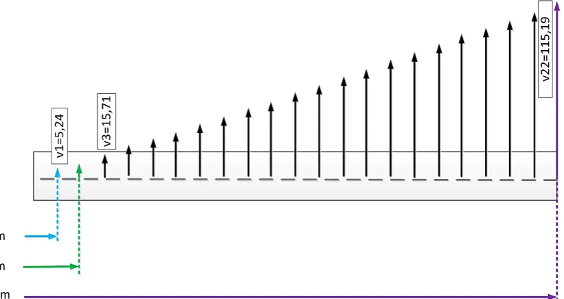
In the next step, the linear velocity has
been calculated at selected distances from the
axis of rotation. This makes it possible to de -termine distribution of the drag force over the
entire length of the blade with the same res -olution as the designated speed. To calculate linear velocity v [m/s], Equation 2 is used. By substituting in Equation 2 as already calculated
angular velocity and the corresponding values of radius R [m] obtained for R = 0.2 m, linear velocity equals to 5.24 [m/s].
(2)
To determine the drag force of the resultant
acting on the blade, the speed was determined at distances of 0.2 m along the entire length of the blade, i.e. from 0 to 4.4 m. Figure 8 shows
a diagram illustrating the approach to calcula-tions of linear velocities according to differ-ent lengths of the rotor blade. Linear velocity v assumes a linear relationship and takes the
value of 115.19 m/s at a predefined required
rotational speed n = 250 rpm.
Fig. 6. Diagram of the mass and aerodynamic loads
To determine the Reynolds Numbers (3), it is necessary to know air density ρ (working fluid), coefficient of dynamic viscosity μ and
characteristic dimension of the object l being
to flow around. These values were determined using the fluid properties calculator [8]. The calculations were performed at 20 ̊C. For this temperature air reaches a density of 1.2047 kg/m3 and a dynamic viscosity coefficient is
1.8205e-5 kg/(m∙s). For the first one consid
-ered, the Reynolds Number for linear velocity v1 equals 69297.38. The values of Re for the other measurement points were calculated in the same way (Figure 10).
(3)
Due to the lower Reynolds Number, drag co
-efficient Cx required to calculate the drag force is read from the drag force coefficient characteristic as a function of angle of attack for Re = 1,800,000
for the roughened surface of the leading edge and
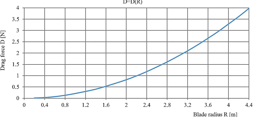
at an angle of attack equal to 2 ̊. Cx for the above conditions is 0.009. The drag force is described in Equation 4.
Fig. 8. Linear velocities according to different lengths of the rotor blades
(4) where: D – generated drag force [N],
Cx – drag coefficient [–],
S – the surface area of the airfoil at an angle of blades α=2° [m2],
ρ – density of air [kg/m3],
v – linear velocity [m/s].
For the first calculation point, i.e. for v = 5.24
and radius R = 0.2 m, drag force D is:
D = 0.009·1.2047·0.053·5.242/2 = 0.01 [N]
The results of drag force D for the other
calculation points are shown in Figure 11. Torque M [Nm] is generated by drag force D described by Equation 5. Figure 12 shows
the results of the calculation of the torque gen -erated by the rotor blade.
M = D · R (5)
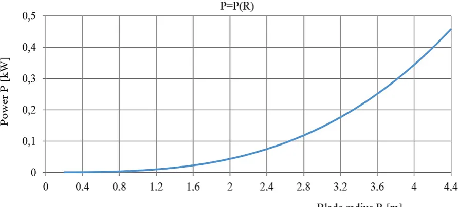
Power P [kW] is needed to drive the
pre-rota-tion described in Equapre-rota-tion 5. To obtain a rotapre-rota-tion -al speed n = 250 [rpm] for the selected radius R1
where torque M = 0.002 Nm, the required power for a drive unit is 0.000043 kW.
(6)
The polynomial designated by the
meth-od of least squares (6) describes the change
Fig. 10. Reynolds Number for the individual measuring points
in power value P depending on the blade ra-dius R. The maximum deviation value by polynomial approximations of degree 3 is: -5.307854604817E-7, while the minimum de
-viation is: 5.98531739350993E-9. The total power resulting from the drive of a single blade rotor was calculated as the sum of the value of the power for the considered blade radii.
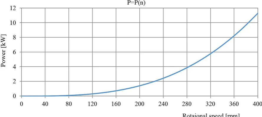
According to the above algorithm, the cal
-culations for the speed range of 0 to 400 rpm
are made. The dependence of the estimated
power required to maintain a certain speed of
rotation of the rotor in the TAURUS gyroplane depending on the value of the frequency of ro
-tation is shown in Figure 14.
CONCLUSIONS
At a speed of n = 250 rpm, the power re
-quired to drive the single blade rotor is 2.75 kW or for the double blade rotor is 5.5 kW. The total torque for the same rotational speed is 210.23 Nm. This is the torque which drives
Fig. 12. Results of the calculations of the torque generated by the rotor blade with α = 2 ̊
Fig. 13. Results of the calculation power required to obtain a rotational speed n = 250 rpm
P(R) = 0.00537532418001592 ∙ R3 - 6.99872258491349E - 8 ∙ R2
a rotor under given conditions in the input. For the drive rotor powered by an electric motor or
the internal combustion engine coupled to the
rotor by gearing, the torque is smaller, which is
related to a gear ratio.
REFERENCES
1. Antkowiak K. Pilotaż - ABC wiatrakowca. Przegląd lotniczy, 9/2011, 2011, 2-5.
2. Delega M., Krzymień W. Weryfikacja rozwiązań prerotacji wirnika wiatrakowca. Prace Instytutu Lotnictwa, 3 (236), 2014, 35-40.
3. http://trendak.eu/models/taurus/tech_data. 4. Stivers S.L., Rice J.F. Aerodynamic character
-istic of four Naca airfoil sections designed for
helicopter rotor blades, Washington, 1946. 5. Szczeciński S. i in. Zespoły wirnikowe silników
turbinowych. WKIŁ, Warszawa 1982.
6. Lipka J. Wytrzymałość maszyn wirnikowych. WNT, Warszawa 1967.
7. Leishman J.G. Principles of Helicopter Aerody
-namics. University of Maryland, College Park, 2006.
8. Fluid Properties Calculator: http://www.mhtl. uwaterloo.ca/old/onlinetools/airprop/airpr.
Fig. 14. Power to maintain a certain rotational speed of the TAURUS gyroplane rotor
![Table 1. Basic performance of the Taurus [3]](https://thumb-us.123doks.com/thumbv2/123dok_us/8808528.1775922/2.595.89.484.412.749/table-basic-performance-taurus.webp)
![Fig. 4. Characteristics of the drag coefficient as a function of angle of attack for Re = 2,600,000.Own elaboration based on [4]](https://thumb-us.123doks.com/thumbv2/123dok_us/8808528.1775922/3.595.116.479.306.504/fig-characteristics-coefficient-function-angle-attack-elaboration-based.webp)