RESEARCH NOTE
SLOPE STABILITY ANALYSIS USING A NON-LINEAR
OPTIMIZATION TECHNIQUE
H. M. V. Samani
Civil Engineering Department, Faculty of Engineering
Shahid Chamran University, Ahwaz, Iran, [email protected]
M. Meidani
Civil Engineering Department, School of Engineering Shiraz University, Shiraz, Iran
(Received: December 27, 2001 – Accepted in Revised Form: February 6, 2003)
Abstract In this study, a limit equilibrium method has been developed that satisfies all conditions of equilibrium and assumes circular slip surfaces. All force and moment equilibrium equations are employed without using simplification assumptions. A non-linear optimization technique is used to solve the system of equations with the corresponding constraints. The proposed method is capable to determine the interslice forces, factor of safety, and the coordinates of the critical slip surface center and the length of its radius. Examples for various unknown slope stability parameters are presented and compared to other conventional methods. The concept of the proposed method can be simply extended to multi-layered soil problems with circular and non-circular slip surfaces.
Key Words Slope Stability, Limit Equilibrium, Nonlinear Optimization, Slip Surface, Factor of Safety
ﻩﺪﻴﻜﭼ
ﻩﺪﻴﻜﭼ
ﻩﺪﻴﻜﭼ
ﻩﺪﻴﻜﭼ
ﻖﻴﻘﺤﺗﻦﻳﺍﺭﺩ
ﻲﻣﺎﺿﺭﺍﺍﺭﻝﺩﺎﻌﺗﻂﻳﺍﺮﺷﻪﻴﻠﻛﻪﻛﺖﺳﺍﻩﺪﺷﻩﺩﺍﺩﻪﻌﺳﻮﺗﻱﺪﺣﻝﺩﺎﻌﺗﺵﻭﺭﻚﻳ ﻭﺪﻳﺎﻤﻧ
ﻲﻣﺽﺮﻓﻱﺍﻩﺮﻳﺍﺩ ﺍﺭﺵﺰﻐﻟﺡﻮﻄﺳ ﺪﻨﻛ
. ﻩﺪﻨﻨﻛﻩﺩﺎﺳﺽﺮﻓﻪﻧﻮﮕﭽﻴﻫﻥﻭﺪﺑ ﺎﻫﺭﻭﺎﺘﺸﮔﻭﺎﻫﻭﺮﻴﻧﻝﺩﺎﻌﺗﺕﻻﺩﺎﻌﻣ
ﺪﻧﺍ ﻩﺪﺷ ﻩﺩﺮﺑ ﺭﺎﻜﺑ ﺵﻭﺭ ﻦﻳﺍ ﺭﺩ
.
ﻣﺩﻮﻴﻗ ﻩﺍﺮﻤﻬﺑ ﺕﻻﺩﺎﻌﻣﻦﻳﺍ ﻞﺣﻱﺍﺮﺑ ﻲﻄﺧ ﺮﻴﻏ ﻱﺯﺎﺳ ﻪﻨﻴﻬﺑ ﺵﻭﺭ ﻪﻃﻮﺑﺮ
ﺖﺳﺍ ﻩﺪﺷﻩﺩﺎﻔﺘﺳﺍ
. ﻉﺎﻌﺷﻭﺵﺰﻐﻟﻩﺮﻳﺍﺩ ﺰﻛﺮﻣﺕﺎﺼﺘﺨﻣ ،ﻱﺍﻪﻌﻄﻗﻦﻴﺑ ﻱﺎﻫﻭﺮﻴﻧﻦﻴﻴﻌﺗﻲﻳﺎﻧﺍﻮﺗﻩﺪﺷﻪﺋﺍﺭﺍﺵﻭﺭ
ﻲﻣﺍﺭﺍﺩﺍﺭﻥﺁ ﺪﺷﺎﺑ
. ﻝﻭﺍﺪﺘﻣﻱﺎﻬﺷﻭﺭﺎﺑﻥﺁﺞﻳﺎﺘﻧﻭﻪﺋﺍﺭﺍﻒﻠﺘﺨﻣﺭﺍﺪﺒﻴﺷﺡﻮﻄﺳﻱﺭﺍﺪﻳﺎﭘﻱﺎﻫﺮﺘﻣﺍﺭﺎﭘﺎﺑﻲﻳﺎﻬﻟﺎﺜﻣ
ﺖﺳﺍ ﻩﺪﺷ ﻪﺴﻳﺎﻘﻣ ﺮﮕﻳﺩ
. ﻲﺘﺣﺍﺭ ﻪﺑ ﻱﺩﺎﻬﻨﺸﻴﭘ ﺵﻭﺭ ﻢﻴﻫﺎﻔﻣ
ﺵﺰﻐﻟ ﺡﻮﻄﺳ ﺎﺑ ﻱﺍ ﻪﻳﻻ ﻱﺎﻬﻛﺎﺧ ﻪﺑ ﻂﺴﺑ ﻞﺑﺎﻗ
ﻲﻣﻱﺍﻩﺮﻳﺍﺩﺮﻴﻏﻭﻱﺍﻩﺮﻳﺍﺩ ﺪﺷﺎﺑ
.
1. INTRODUCTION
Many methods for analyzing slope stability have been developed. The limit equilibrium methods are considered the most common ones for practical purposes (Duncan [1]). Equilibrium methods, such as Lowe and Karafiath [2] and U.S. Army Corps of Engineers [3] satisfy force equilibrium conditions. Ordinary method of slices (Fellenius [4]) satisfies moment equilibrium conditions. Bishop’s modified method [5] satisfies moment and vertical force equlibriums. Morganstern and Price’s method [6],
as do methods that satisfy all conditions of equilibrium (Duncan and wright [9]).
Locating the slip surface with the lowest factor of safety is an important part of analyzing slope
stability. Most of the methods that assume circular critical slip surfaces use systematic changes in the position of the center of circle and length of the radius to find the critical circle that has the lowest factor of safety. Nguyen [10] and Chen and Shao [11] used optimization techniques to find the critical slip surface. Spencer [12] found that circular slip surfaces were as critical as logarithmic spiral slip surfaces for all practical purposes. Celestino and Duncan [13] and Spencer found that, in analyses where the slip surface was allowed to take any shape, the critical slip surface found by the search was essentially circular.
In this study, a method has been developed that satisfies all conditions of equilibrium and assumes the slip surfaces to be circular. A non-linear optimization technique has been employed in the analysis to determine the unknown parameters.
2. PROPOSED METHOD
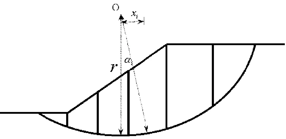
Figure 1 shows a potential sliding mass along a trial slip surface through a homogeneous slope. The sliding mass is subdivided into a number of vertical slices. The free body diagram of a slice is
i
W
1+
i
E
1
+
i
X
i
S
i
P
i
E
i
X
Figure 2. Free body diagram of a slice.
illustrated in Figure 2 The forces acting on the slice are its own weight Wi , side forces, both which have
shear component Xi , and normal components Ei ,
and the shear resistance Si and the normal force Pi
which act on the base of the slice. Equating the moment of the weight of the sliding mass with the moment of the external forces acting on the slip surface, about the center O of the slip circular surface yields:
r S x
Wi i i
∑
⋅ =∑
⋅ (1)in which Xi and r are shown in Figure 1.
The relation between the shear strength of failure and equilibrium shear stress along the shear surface can be expressed as:
F f
τ =
τ (2)
in which F is the factor of safety. Combining Equation 2 with the Mohr-Columb equation gives:
(
)
[
C P l u tan]
F 1
i i
i − ⋅ φ ′
+ ′ =
τ (3)
where:
C’ = drained cohesion of the soil
φ’ = drained internal friction angle l i = the slice base length
u i = pore water pressure
Vertical equilibrium for the slice i gives: sin S cos P X X
Wi + i − i+1= i⋅ αi + i ⋅ αi (4) Resolving for Piyields:
(
W X X)
sec S tanPi = i + i − i+1 ⋅ αi − i⋅ αi (5) Substituting the last expression in Equation 3 and after manipulation gives:
{
(
)
[
+ − ⋅ α − ⋅]
⋅ φ′}
+ ⋅′ φ′ ⋅ α + = +
∑
tan l u sec X X W l C tan tan F 1 S i i i 1 i i i i i i (6)Hence, by substituting the last expression for Si in
Equation 1 yields:
(
)
[
]
∑
∑
= α ⋅ ⋅ − φ′ ⋅ α + φ′ ⋅ − α − + + ⋅′ + 0 sin W r tan tan F tan l u sec X X W l C r i i i i i i 1 i i i i (7) The summation of the normal interslice forcesshould also be zero:
(
Ei −Ei 1)
=0∑
+ (8)Resolving the forces acting on the slice in a tangential direction to the base of the slice:
i 1 i i i 1 i i
i (E E ) cos (W X X ) sec
S = − + ⋅ α + + − + ⋅ α
(9) Therefore:
∑
∑
(Ei−Ei+1)= Si⋅secαi−(Wi+Xi−Xi+1)⋅tanαi(10) Insertion of the value of Si from Equation 6 into
Equation 10 yields:
(
)
{
}
α −φ′ ⋅ α + φ′ − α − + +
∑
+ i i i i i 1 i i i i ' sec tan tan F tan l u sec X X W l C
(
Wi +Xi −Xi+1)
tanαi =0(11) Equations 7 and 11 are the moment and force
equilibrium equations, respectively. These equations are considered to be the fundamental equations, which should be solved to determine the unknowns Xi for every slice and the factor of safety F. The
number of equations is less than the number of unknowns and the system is thus indeterminate.
3. OPTIMIZATION TECHNIQUE
In this study, it is desired to solve Equations 7 and 11 to obtain the shear interslice forces Xi, and the
possible to constraint the unknown values to lower and upper limits in order to be able to obtain the appropriate solution. This requires adequate experience and engineering judgment. In this study, an optimization technique has been used to solve the problem. In this regard the objective function is selected as:
2
2 (Eq.11)
) 7 . Eq ( Function
Objective = + (12)
which is subjected to the following constraints:
F r r Yc c Yc Xc c Xc X N X X 2 X X 1 X ) Limit Upper ( F 0 ) Limit Upper ( r ) Limit Lower ( ) Limit Upper ( y ) Limit Lower ( ) Limit Upper ( x ) Limit Lower ( ) Limit Upper ( X ) Limit Lower ( : : ) Limit Upper ( X ) Limit Lower ( ) Limit Upper ( X ) Limit Lower ( N N 2 2 1 1 ≤ ≤ ≤ ≤ ≤ ≤ ≤ ≤ ≤ ≤ ≤ ≤ ≤ ≤ (13) The transformed conjugate nonlinear optimization
method (Box 1966) is used for minimizing the objective function given by Equation 12. In this technique which is an iterative method, each iteration of the procedure commences with a search down n linearly independent directions called the conjugate directions. The method does not require calculation of derivatives and it is based on a searching procedure. The method starts searching from different initial points distributed in the problem domain in order to find the global minimum. It is obvious that the unknowns which satisfy Equations 7 and 11 and the constraints given by Equation 13 should make the objective function given by Equation 12 equal or close to zero. This goal is achieved by the optimization technique.
A computer program has been developed in this study in which circular slip surfaces are concerned and the slip surface is divided into a number of vertical slices. Based on the dimensions of the slice and soil properties, the interslice forces are determined. This program is linked to the optimization program in order to determine the
unknowns given by Equation 12 and 13. The coordinates of the critical slip surface and its center are obtained by a searching technique in a given domain . The optimizatin technique solves for the factor of safety and interslices forces starting from an arbirary circle and proceeds for other circles in the given domain. The critical slip circle will be the one with the lowest factor of safty. The computer program is adapted by such a way that if desired any of the unknowns can be taken out of the optimization procedure and given as known parameters.
In this stage of the study, to examine the method, a number of simple cases with homogeneous and dry soils have been analyzed.
4. ILLUSTRATIVE EXAMPLES
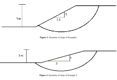
Example 1
The geometry of the slope is shown in Figure 3. The parameters of the soil are given as:γd = 16 kN/m3 c’ = 10 kPa
φ’ = 15°
The coordinates of the slip circle center and its radius are:
xc = 12.6 m. yc = 20.6 m. r = 10.6 m.
As was mentioned before, a computer program has been written so that any of the unknowns can be taken out of the optimization procedure and given as known parameters. In this example, the slip surface geometry parameters are taken out of the optimization procedure and given as known parameters. In examples 3 and 4, which will be illustrated later, the slip circle geometry parameters are considered to be unknowns, i.e., they are included in the optimization parameters.
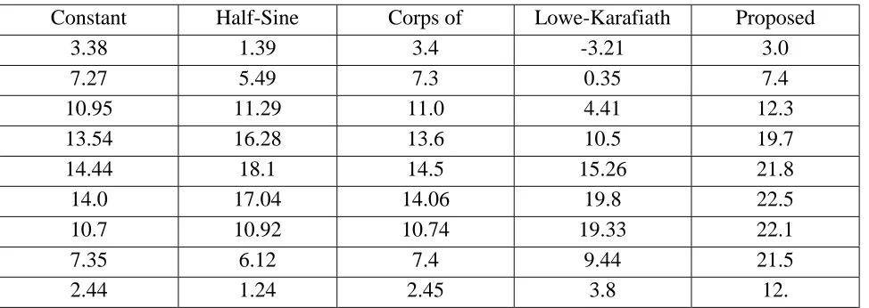
Factors of safety determined by the proposed method and other conventional slope stability analysis methods for 10 slices are given in Table 1. Interslice shear forces are given in Table 2.
in Figure 4. The soil parameters are given as:
γd = 18 kN/m
3
c’ = 12 kPa
φ’ = 10°
The coordinates of the slip circle center and its radius are:
xc = 14.2 m. yc = 17.4 m.
r = 9.4 m.
Results of this example are given in Tables 3 and 4.
Example 3
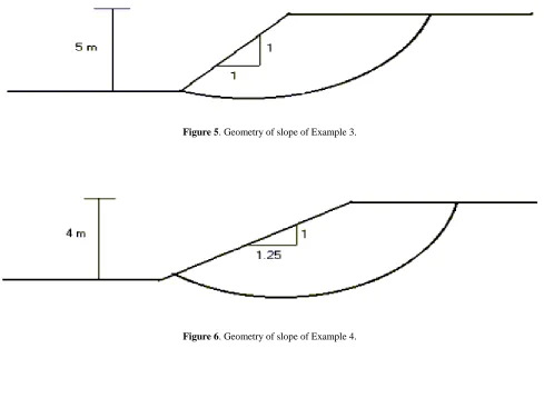
The slope of this example is illustrated in Figure 5. In this example, it is desired to find the coordinates of the critical slip circle center and its diameter in addition to the shear interslice forces and factor of safety.Soil properties are given as:
γd = 16 kN/m3
Figure 3. Geometry of slope of Example1.
Figure 4. Geometry of slope of Example 2.
TABLE 1. Factors of Safety Calculated by Different Methods for Example 1.
c’ = 10 kPa
φ’ = 10°
The results found by the proposed method and other methods are given in Tables 5 and 6. The calculated coordinates of the of critical slip circle TABLE 2. Interslice Shear Forces Calculated by Different Methods for Example 1.
Constant Interslice
Half-Sine
Corps of
Lowe-Karafiath
Proposed
3.81 1.62
0.96 2.14
0.60
7.15 5.31
3.35 4.98
8.60
9.86 9.75
6.76 8.2
11.7
11.41 12.92
10.27 10.95
13.6
11.46 13.35
12.64 12.37
13.9
9.85 10.76
12.7 11.7
12.35
7.57 7.39
10.72
9.55
11.8
3.32 2.46
5.21 2.54
1.69
-0.4 -0.2
-0.58
-0.35
-1.35
TABLE 3. Factors of Safety Calculated by Various Methods for Example 2.
Fellenius Bishop
Janbu
Morgenstern-Price
Proposed
method
2.263 2.394
2.125 2.391
2.437
TABLE 4. Interslice Shear Forces Calculated by Various Methods for Example 2.
Constant Half-Sine Corps
of
Lowe-Karafiath
Proposed
3.38 1.39 3.4 -3.21 3.0
7.27 5.49 7.3 0.35 7.4
10.95 11.29 11.0
4.41 12.3
13.54 16.28 13.6
10.5 19.7
14.44 18.1 14.5 15.26 21.8
center and radius are:
xc = 10.8 m.
yc = 17.0 m
r = 7.0 m.
Example 4
Geometry of the slope is shown in Figure 6. Similar to the previous example, xc,yc and r of the critical slip circle in addition
to the interslice shear forces and factor of safety are to be determined. Soil properties are given as:
γd = 16kN/m
3
c’ = 10kPa
φ’ = 10°
The results associated with the factor of safety and the shear interslice forces are given in Tables 7 and 8. The calculated coordinates of the of critical slip circle center and radius are:
xc = 10.8 m.
yc = 16.2 m
r = 6.2 m.
5. CONCLUSION
In general, the results found by the proposed method indicate that it gives slightly higher factor of safeties. The main advantage of the developed method compared to other methods that satisfy both force and moment equilibriums is that no simplification assumptions are required to be used Figure 5. Geometry of slope of Example 3.
in the developed method. The non-linear optimization technique employed in this study to solve the system of the equilibrium equations with the corresponding constraints is a powerful mean because it does not require calculation of derivatives and it is based on a searching procedure. In this study, simple cases are concerned in which the soil is homogeneous, dry and there is no earthquake force acting on the slices. The concept of the proposed method can be simply extended to multi-layered soil problems with circular and non-circular slip surfaces.
6. ACKNOWLEDGEMENT
The authors would like to acknowledge the
financial support of Shahid Chamran University, Ahvaz, Iran.
7. APPENDIX I NOTATION
Xi interslice shear force component
Ei interslice normal force component
Si shear resistance on the base of the slice
shear stress of faillure
Pi normal force on the base of the slice
Wi slice weight
F factor of safety
f
τ
shear strength of failureτ
equilibrium shear stressC’ cohesion of the soil TABLE 5. Factors of Safety Calculated by Various Methods for Example 3.
Fellenius Bishop Janbu Morgenstern-Price Proposed method
1.081 1.103 1.069 1.102 1.106
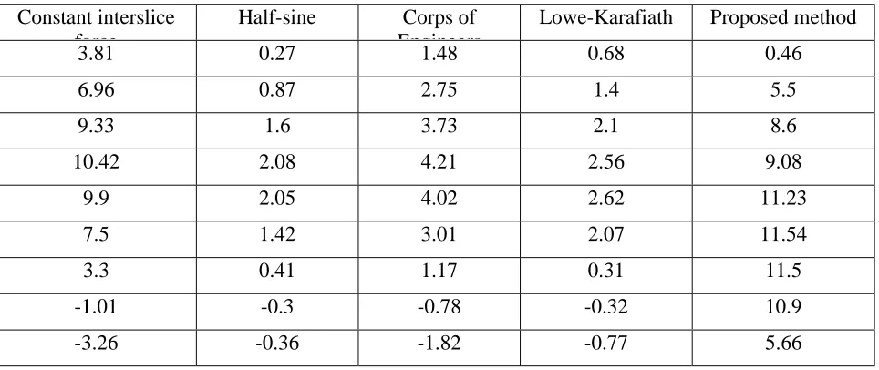
TABLE 6. Interslice Shear Forces Calculated by Various Methods for Example 3.
Constant interslice force
Half-sine Corps of
Engineers
Lowe-Karafiath Proposed method
3.81 0.27 1.48 0.68 0.46
6.96 0.87 2.75 1.4 5.5
9.33 1.6 3.73 2.1 8.6
10.42 2.08 4.21 2.56 9.08
9.9 2.05 4.02 2.62 11.23
7.5 1.42 3.01 2.07 11.54
3.3 0.41 1.17 0.31 11.5
-1.01 -0.3 -0.78 -0.32 10.9
φ’ internal friction angle
l I the slice base length u I pore water pressure
i
α
angle between vertical line that passes through the circle center and the radius that passes through the middle of the slice basexc x coordinate of slip circle yc y coordinate of slip circle r radius of slip circle
γd dry unit weight
8. REFERENCES
1. Duncan, J. M., “State of the Art: Limit Equilibrium and Finite Element Analysis of Slopes”, J. of Geotechnical Engrg., ASCE, Vol. 122, No. 7., (1996), 577-593. 2. Lowe, J. and Karafiath, L., “Stability of Earth Dams upon
Draw Down”, Proc., 1st Pan-Am. Conf. On Soil Mech.
and Found. Engrg., Mexico City, 2, (1960), 537-552. 3. U. S. Army Corps of Engineers, “Engineering and Design
Stability of Earth and Rockfill Dams”, Engr. Manual EM 1110-2-1902, Dept. of The Army, Corp of Engrs., Ofc. Of The Chf. Of Engrs, (1970).
4. Fellenius, W., “Erdstatische Berechnungen mit Reibung und Kohasion”, Ernst, Berlin (in German), (1927). TABLE 7. Factors of Safety Calculated by Various Methods for Example 4.
Fellenius Bishop Janbu Morgenstern-Price Proposed method
1.401 1.428 1.366 1.426 1.450
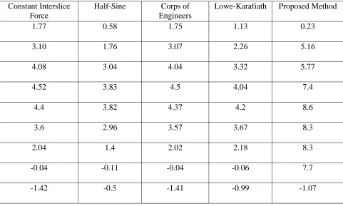
TABLE 8. Interslice Shear Forces Calculated by Various Methods for Example 4.
Constant Interslice Force
Half-Sine Corps of
Engineers
Lowe-Karafiath Proposed Method
1.77 0.58 1.75 1.13 0.23
3.10 1.76 3.07 2.26 5.16
4.08 3.04 4.04 3.32 5.77
4.52 3.83 4.5 4.04 7.4
4.4 3.82 4.37 4.2 8.6
3.6 2.96 3.57 3.67 8.3
2.04 1.4 2.02 2.18 8.3
-0.04 -0.11 -0.04 -0.06 7.7
5. Bishop, A. W., “The Use of The Slip Circle in The Stability Analysis of Slopes”, Geotechnique, London, 5(1), (1955), 7-17.
6. Morganstern, N. R. and Price, V. E., “ The Analysis of The Stability of General Slip Surfaces”, Geotechnique, London, 15(1), (1965), 79-93.
7. Janbu, N., “ Slope Stability Computation”, Soil Mech. And Found. Engrg. Rep., The Technical University of Norway, Trondheim, Norway, (1968).
8. Spencer, E., “ A Method of Analysis of The Stability of Embankments Assuming Parallel Interslice Forces”,
Geotechnique, London, 17(1), (1967), 11-26.
9. Duncan, J. M. and Wright, S. G., “The Accuracy of Equilibrium Methods of Slope Stability Analysis”, Engrg. Geol., 16(1), (1980), 5-17.
10. Nguyen, V. U., “Determination of Critical Slope Failure
Surface”, J. Geotech. Engrg., ASCE, 111(2), (1985), 238-250.
11. Chen, Z. and Shao, C., “Evaluation of Minimum Factor of Safety in Slope Stability Analysis”, Can. Geotech. J., 25(4), (1988), 735-748.
12. Spencer, E., “ Circular and Logarithmic Spiral Slip Surfaces”, J. Soil Mech. and Found. Div., ASCE, 95(1), (1969), 227- 234.
13. Celestino, T. B. and Duncan, J. M., “ Simplified Search for Non-Circular Slip Surface”, Proc., 10th Int. Conf. on Soil Mech. And Found. Engrg., A. A. Balkema, Rotterdam, The Netherlands, 3, (1981), 391-394.