MULTILEVEL INPUT RING-TCM CODING SCHEME:
A METHOD FOR GENERATING HIGH-RATE CODES
M. Ahmadian-Attari
Dept. of Electrical Engineering, K. N. Toosi University of Technology P.O.Box 16315-1355, Tehran, Iran, Fax: +98 21 862066, [email protected]
(Received: September 29, 1999 – Accepted in Revised Form: March 1, 2001)
Abstract The capability of multilevel input ring-TCM coding scheme for generating high-rate codes with improved symbol Hamming and squared Euclidean distances is demonstrated. The existence of uniform codes and the decoder complexity are also considered.
Key Words High-Rate, Non-Binary, Ring-TCM, Multilevel, Uniform Code
ﻴﻜﭼ
ﻩﺪ
...
ﺪﻛ ﺬﮔ
ﺭﺍ
TCM
ﻞﺒﻤﺳﻲﺘﻗﻭ ﻱﻮﻘﻠﺣ
ﻲﺟﻭﺮﺧﻭﻱﺩﻭﺭﻭﻱﺎﻫ
ﺪﻛ ﻪﻘﻠﺣﺮﺻﺎﻨﻋ
ﺩﺍﺪﻋﺍﺯﺍﻲﺗﻭﺎﻔﺘﻣﻱﺎﻫ
ﻣ ﺢﻴﺤﺻ ﺜ ﻼ
Zp
ﻭ
Zq
ﺪﻛﺪﻴﻟﻮﺗ ﺖﻴﻠﺑﺎﻗ ﺎﻬﻧﺁ ﺯﺍﻲﻜﻳ ﻪﻛ ﺖﺳﺍ ﻲﺒﻟﺎﺟ ﺹﺍﻮﺧ ﻱﺍﺭﺍﺩ ﺪﻨﺷﺎﺑ
ﺎﺑ ﻻﺎﺑ ﺥﺮﻧ ﺎﺑ ﻱﺎﻫ
ﻲﮔﺪﻴﭽﻴﭘ
ﻲﻣﻝﻮﺒﻗﻞﺑﺎﻗﻲﺗﺎﺒﺳﺎﺤﻣ ﺪﺷﺎﺑ
. ﻪﻟﺎﻘﻣﻦﻳﺍﺭﺩ
ﻲﮕﻧﻮﮕﭼ
ﺪﻛﻲﺣﺍﺮﻃ ﮔ
ﺥﺮﻧﺎﺑﺪﻛﺪﻴﻟﻮﺗﻱﺍﺮﺑﺐﺳﺎﻨﻣﺭﺍﺬ
ﺍﺭﺍﻩﺍﻮﺨﻟﺩ ﺋ
ﻭﻪـ ﻲﮔﺪﻴﭽﻴﭘ
ﺭﺍﺩﺮﺑﺪﻛﻲﺗﺎﺒﺳﺎﺤﻣ
ﻪﺑﺎﺸﻣ ﻱﺎﻫﺪﻛﺎﺑ
ﻲﻳﺎﺗﻭﺩ
ﺖﺳﺍ ﻩﺪﺷﻪﺴﻳﺎﻘﻣ
.
ﺪﻛ ﺎﻫ ﻳ
ﻦﻳﺍ ﻪﺑﻪﻛﻲـ
ﻲﻣﻲﺣﺍﺮﻃﺵﻭﺭ
ﻪﻜﻨﻳﺍﺮﺑﻩﻭﻼﻋﺪﻧﻮﺷ ﻲﮔﺪﻴﭽﻴﭘ
ﺭﺩﺩﺮﺑﺭﺎﻛﻱﺍﺮﺑﺍﺭﻱﺮﺘﻬﺑﺕﺎﺼﺨﺸﻣ،ﺪﻧﺭﺍﺩﻱﺮﺘﻤﻛﻲﺗﺎﺒﺳﺎﺤﻣ
ﻱﺎﻬﻟﺎﻧﺎﻛ ﮔ ﻨﻳﺪﻴﻓﻭﻲﺳﻮ ﮓ
ﻲﻣﻥﺎﺸﻧ ﺪﻨﻫﺩ
.
INTRODUCTION
Modulo-p input, modulo-q output ring-TCM codes, where p and q are powers of two, were originally proposed by the author as an efficient coding scheme for fading channels [1,2]. In this scheme by selecting p, q, and v (the number of memory cells) for a given k and n, the condition of avoiding parallel trellis transitions is satisfied. Then, by a computer search program, the best codes with maximum diversity factor, L, and maximum product squared Euclidean distance, PSED, which are the most important parameters for designing codes for fading channels applications [3], are found. In this paper we show the capability of a special version of these codes for generating high-rate codes with reasonable decoder complexity.
HIGH-RATE TRELLIS CODES
High-rate, or low-redundancy convolutional codes are of interest for bandwidth-constrained applications. The trellis diagram corresponding to such an encoder would have a lot of branches departing and entering each state and a complex Viterbi decoder. High-rate binary convolutional codes are tailored by puncturing a low-rate code, called the
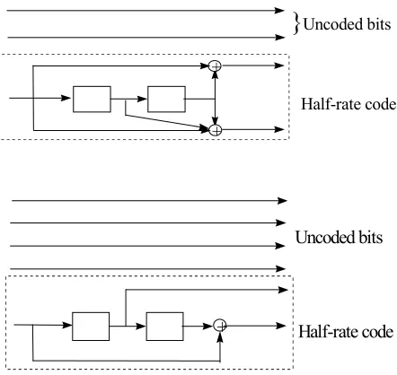
parent code [4-6]. High-rate TCM codes are obtained by adding uncoded bits to a low-rate good code [7] as shown in Figure 1. This results in parallel trellis transitions which reduces L and d2
free, the symbol
Hamming and squared Euclidean distances, respectively. This paper introduces an alternative approach to these methods.
Figure 1. Obtaining rate 3/4 and 5/6 TCM codes from a lower rate code.
+
+
}
Uncoded bitsHalf-rate code
+
Uncoded bits
Figure 2. Modulo-p input, modulo-q output encoder.
MULTILEVEL INPUT, Q-ARY OUTPUT CODES
Consider the multilevel systematic convolutional encoder (MCE) shown in Figure 2, where input and output symbols are elements of modulo-p and modulo-q rings of integers, respectively, and additions and multiplications are performed in Zq.
Non-systematic codes do not require p to be a power of two or even a non-prime integer. Also for
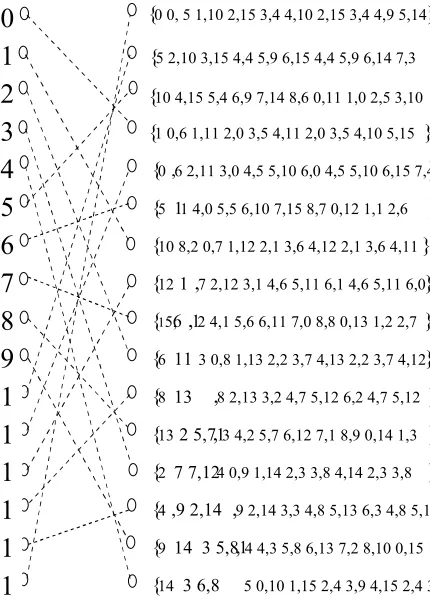
k > 1 it is not necessary that all input symbols belong to the same set of integers. An example is designed in Figure 3, where symbols from GF(3) and GF(5) are encoded to generate two symbols from Z16.
The rate of this code is Rc = (log1615)/2 = 0.488
and the system is capable of transmitting (log23 +
log25) Rc = 1.908 bits per symbol. The closest
uncoded scheme to be compared with is QPSK, which transmits 2 bits per symbol. The number of branches entering or leaving any node in its 16-state trellis diagram is 31 x 51 = 15. In Figure 4
dashed lines indicate the absence of one transition from each state. The shortest error event path is S0S7S3S0 with d2free = 5.854 and L = 5. Denoting
the set of 15 vectors corresponding to states S0, S1,
and S2, by ϕ0, ϕ1, and ϕ2, respectively, it is seen
that all sets corresponding to other states are their cossets. Therefore, existence of uniform codes from this class may be assessed.
To obtain codes with larger L and PSED, it is customary to expand space the state of a
Figure 3. A non-systematic encoder with inputs from different sets of integers.
Figure. 4. Trellis diagram of the encoder shown in Figure. 3, only forbidden transitions are sketched.
code by powers of two. One advantage of this method is the capability of increasing L without doubling the number of encoder’s state. Hence, there would be a wide range of possible trellis diagrams from one with parallel transitions to a fully connected one and from the latter to a
0
1
2
3
4
5
6
7
8
9
1
1
1
1
1
1
{0 0, 5 1,10 2,15 3,4 4,10 2,15 3,4 4,9 5,14 6 4 4 9 14 6 3 8 8 } {5 2,10 3,15 4,4 5,9 6,15 4,4 5,9 6,14 7,3
8 11 0 0 1 2 10 3 1 4 } {10 4,15 5,4 6,9 7,14 8,6 0,11 1,0 2,5 3,10
4 0 2 3 10 4 1 4 6 } {1 0,6 1,11 2,0 3,5 4,11 2,0 3,5 4,10 5,15 }
{0 4,
6 2,11 3,0 4,5 5,10 6,0 4,5 5,10 6,15 7,4 8 12 0 1 1 6 2 11 3 } {5
6
11 4,0 5,5 6,10 7,15 8,7 0,12 1,1 2,6 3 11 4 1 2 6 3 11 4 0 } {10 8,2 0,7 1,12 2,1 3,6 4,12 2,1 3,6 4,11
0 6 6 4 11 0 6 }
{12 3 1 ,
7 2,12 3,1 4,6 5,11 6,1 4,6 5,11 6,0
8 13 0 2 1 2 }
{1 5,6 ,12 4,1 5,6 6,11 7,0 8,8 0,13 1,2 2,7 } {6 11 3 0,8 1,13 2,2 3,7 4,13 2,2 3,7 4,12
1 6 4 12 1 6 }
{8 2 13 ,
8 2,13 3,2 4,7 5,12 6,2 4,7 5,12 6 1 6 8 14 0 3 1 } {13
4 2 5,7 ,13 4,2 5,7 6,12 7,1 8,9 0,14 1,3 2 8 3 13 4 3 2 8 3 } {2
6 7 7,12 4 0,9 1,14 2,3 3,8 4,14 2,3 3,8 4 13 2 6 8 4 13 } {4
1
,9 2,14 ,9 2,14 3,3 4,8 5,13 6,3 4,8 5,13
6 2 8 1 0 }
{9
3 14 3 5,8 ,1
4 4,3 5,8 6,13 7,2 8,10 0,15 1,4 2 9 3 14 4 4 2 }
{14 3 6,8 5 0,10 1,15 2,4 3,9 4,15 2,4 3,9
Figure 5. A semi-systematic encoder with inputs from different sets of integers.
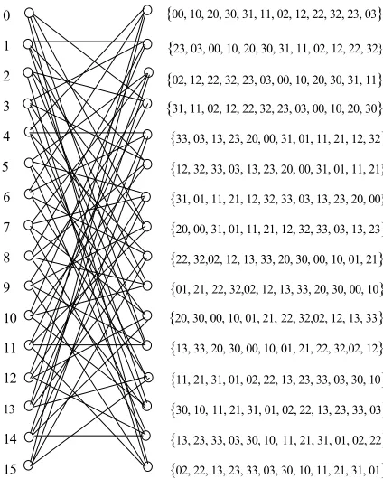
half-connected one. The next example is a semi-systematic code shown in Figure 5.
By selecting a2 from GF(3) instead of Z4, only
12 branches would inter or leave any node in its 16-state trellis diagram. In Figure 6 only transitions, which are deleted by this technique, are represented. This modification results in an improvement in the code parameters compared to the other 16-state codes with fully connected trellis or parallel transitions as summarized in Table 1. Table 1 compares some possible ways to construct a 16-state encoder, where the number of branches, nbr,, is so designed as to be equal or
less than the number of states, nst and r indicates
Figure 6. Trellis diagram of ring code (12)(32)(11)/12;only deleted transitions from a fully connected trellis are plotted.
the throughput of the system.
Ring-TCM codes are defined in this table by their corresponding coefficients as:
g g g gk g gk g g gk f f f
ν ν ν ν ν ν ν ν
1 2 1 1
1 2
1 01 02 0 1 1
K − −K −K K / −K . Since the
second and third codes have a fully connected
TABLE 1. Some Possible Schemes for Constructing 16-State Codes.
No. Code Scheme Rc nst nbr L d2free r PSED C
1 00 00 05 07 Ungerboeck [7] 0.75 16 8 1 1.628 2.25 8.25
2 (21)(13)/10 Z4 to Z16 0.5 16 16 4 6.15 2 8.9 8.55
3 (69)(13)/14 Z4 to Z16 0.5 16 16 6 5.4 2 3.58 8.55
4 (26)(14)/7 GF(2) & Z8 to Z16 0.5 16 16 4 5.08 2 5.89 8.55
5 (21)(54)/3 GF(3) & GF(5) to Z16 0488 16 15 5 5.854 1.9 5.4 8.46
6 (12)(32)(11)/12 GF(3) & Z4 to Z4 0.896 16 12 3 6.0 3.2 8.0 8.13
7 (23)(13)(22)/11 GF(3) to Z4 0.792 16 9 2 8.0 2.5 16.0 7.7
+ + +
a2∈GF( )3
a1∈Z4 x1∈Z4
x2∈Z4
2 1 2 3 1 1
1 2
0
1
2
3
4
5
6
7
8
9
10
11
12
13
14
15
{00, 10, 20, 30, 31, 11, 02, 12, 22, 32, 23, 03}
{23, 03, 00, 10, 20, 30, 31, 11, 02, 12, 22, 32}
{02, 12, 22, 32, 23, 03, 00, 10, 20, 30, 31, 11} {31, 11, 02, 12, 22, 32, 23, 03, 00, 10, 20, 30} {33, 03, 13, 23, 20, 00, 31, 01, 11, 21, 12, 32}
{12, 32, 33, 03, 13, 23, 20, 00, 31, 01, 11, 21}
{31, 01, 11, 21, 12, 32, 33, 03, 13, 23, 20, 00}
{20, 00, 31, 01, 11, 21, 12, 32, 33, 03, 13, 23} {22, 32,02, 12, 13, 33, 20, 30, 00, 10, 01, 21}
{01, 21,22, 32,02, 12, 13, 33, 20, 30, 00, 10}
{13, 33, 20, 30, 00, 10, 01, 21, 22, 32,02, 12}
{20, 30, 00, 10, 01, 21,22, 32,02, 12, 13, 33}
TABLE 2. Possible Solutions for m and n for Bit-to-Symbol Conversion.
trellis their trellis diagrams are not plotted. The encoder of the last code in this table is similar to Figure 5 with the exception that x1is obtained by
combining a1 and a2. Now, 7 out of 16 branches
are removed and results in a longer error event path.
Because the total number of branches in not always divisible by the number of states, the trellis diagram would be non-homogeneous in the sense of lacking some transitions in a stage. Notice that this differs from the case in which different number of branches leave or enter each state [8]. This virtue can cause a longer error event path, which is desirable.
Another advantage of this method is the possibility of constructing codes with any rate of interest; e.g., (log26 3) / , (log29 4) / ,L. The sixth and seventh codes of Table 1 are good competitors for the Ungerboeck code. Since the information sequence is normally a binary stream, this scheme requires a binary to multilevel conversion. When pi (i = 1, 2, ..., k) are not
powers of two, the number of symbols generated by this converter does not match the number of bits in the data stream. Because all information bits should be converted to the ring symbols without any loss, the closest integers m and n to satisfy the inequality 2m in
i
p
≤
∑
offer the conversion strategy. For the first example wehave 2 3 5 15
2 3 9
m n n m
n
≤ × ⇒ ≤ log =
log . . The nearest
solutions for m and n are given it in Table 2.
By selecting n = 2 and m = 7 the converter is delivered blocks of 7 bits and generates 2 symbols belonging to GF(3) and 2 symbols belonging to
GF(5) but only 27 = 128 out of these 32x52 = 225
possible combinations are enough to convey the information and the remaining 97 are not used. Such a multilevel source is not uniform since the probability of generating symbols is not the same in all cases. As the length of the binary blocks is increased, the conversion will be more efficient. The price of this accurate bit-to-symbol conversion is an increase in the memory of the converter. It is seen that binary blocks of length 39 can be converted into blocks consisting of ten GF(3) and ten GF(5) symbols, which can be sent with equal probability.
DECODER COMPLEXITY
When the Viterbi decoder is designed for ring-TCM codes, the trellis branches are labeled by elements of a ring rather than bits. Also, the number of branches originating from each node of the trellis and therefore, the number of path metrics to be compared at each step will be increased by a factor of (p/2)k compared to a
binary TCM with the same k and nst.
The computation consists of adding the accumulated metrics to the branch weight, comparing the resulting metrics, and selecting the lowest ones as the new state metrics. We use the complexity measure defined in [9] as: C = log2(CPBM + CACS),
where CPBM and CACS are the complexities of
computing the parallel branch metrics and add, compare, select units, respectively. The total number of branches at each stage is: nst.pk. Since
each branch is labeled by n-tuple symbols, the
n 1 2 3 4 5 6 7 8 9 10
m 3 7 11 15 19 23 27 31 35 39
number of additions and comparisons required to determine the branch metrics are nadd = n.nst.pk,
and ncomp = nst(pk – 1). In order to compare the
complexity of codes with different dimensions, the number of overall computations is normalized to two-dimensional case. Therefore, the normalized complexity of the decoder in the absence of parallel transitions is given by: C = log2CACS =
log2{nst[(n + 1)pk – 1]/n}. The decoder
complexities of sample codes are given in the last column of Table 1 for comparison. Not only the sixth and seventh codes obtain better parameters, they are also less complex than their binary counterpart.
CONCLUSIONS
h Multilevel input ring-TCM coding scheme, apart from advantages of modulo-p input, modulo-q output ring-TCM codes could generate high-rate codes with larger L and PSED.
h Because of lacking parallel trellis transitions these codes are less complex than their 2-dimensional TCM counterparts with parallel transitions.
h Uniform codes from this class exist.
LIST OF SYMBOLS AND ABBREVIATIONS
TCM Trellis Coded Modulation GF(q) Field of integers modulo-q
Zq Ring of integers modulo-q
Rc = k/n Rate of a code with k input and n
output symbols
v Number of memory cells in a
convolutional encoder
L Diversity factor, the symbol
Hamming distance
PSED Product Squared Euclidean Distance
d2
free Squared Euclidean distance
MCE Multilevel Convolutional Encoder
nst Number of state in a trellis code
nbr Number of branches in a trellis
code
r Throughput, the number of
information bits in a transmitted symbol
C Computational complexity
CPBM Complexity of Parallel Branch
Metric unit in the Viterbi decoder
CACS Complexity of Add, Compare,
Select unit in the Viterbi decoder
REFERENSES
1 . Ahmadian-Attari, M. and Farrell, P. G., “Class of TCM
Codes Over Rings of Integers Modulo-q”, Electronics
Letters, Vol. 32, No. 18, (August 29, 1996), 1668-1670. 2. Ahmadian-Attari, M. and Farrell, P. G., “Efficient
Ring-TCM Codes Over Fading Channels”, IEEE Proc.
GlobeCom’96, London, UK, (November 18-22, 1996), 1248-1252.
3. Divsalar, D. and Simon, M. K., “The Design of Trellis Coded MPSK for Fading Channels: Performance
Criteria”, IEEE Trans. COM-36, No. 9, (September.
1988), 1004-1012.
4. Cain, J. B., Clark, G. C. Jr. and Geist, J. M., “Punctured Convolutional Codes of Rate (n-1)/n and Simplified
Maximum Likelihood Decoding”, IEEE Trans. IT-25,
No.1, (January. 1979), 97-100.
5. Haccoun, D. and Begin, G. ,“High-Rate Punctured Convolutional Codes for Viterbi and Sequential
Decoding”, IEEE Trans. COM-37, No. 11, (November.
1989),1113-1125.
6. Begin, G. and Haccoun, D. “High-Rate Punctured Convolutional Codes: Structure, Properties and
Construction Technique”, IEEE Trans. COM-37, No. 12,
(December. 1989), 1381-1385.
7. Ungerboeck, G., “Channel Coding with Multilevel / Phase
Signals”, IEEE Trans. IT-28, No.1, (January. 1982),
55-67.
Binary Adder Channel with Two Users”, IEEE Transactions IT-32, No. 6, (November. 1986), 787-796.
9. Pietrobon, S. S. and Costello, D. J. Jr., “Trellis Coding
with Multidimensional QAM”, IEEE Trans. IT-39, No.