International Journal of Engineering
J o u r n a l H o m e p a g e : w w w . i j e . i rAnalysis of Oscillation Amplitude and Phase Error in Multiphase LC Oscillators
S. Seifi, H. Miar-Naimi*
Department of Electrical Engineering, Babol University of Technology, Iran
P A P E R I N F O
Paper history:
Received 30 September 2012
Received in revised form 30 December 2012 Accepted 24 January 2013
Keywords:
Coupling Factors Fabrication Mismatches Multiphase LC Oscillators Phase Errors
Wireless Communications
A B S T R A C T
This work proposes a novel method to find the phase error and oscillation amplitude in multiphase LC oscillators. A mathematical approach is used to find the relationship between every stage's output phase and its coupling factor. To much more general analysis, every stage assumed to have a different coupling factor. The mismatches in LC tanks are considered as the main source of phase errors and accordingly the phase deviation of each stage is calculated in a distinct equation. Then, the amplitude of oscillation for each stage is individually derived using phase error results. Not only considering different coupling factors increases the generality of this work but also the results are in better conformance with simulations compared to previous works. The theoretical results are evaluated and confirmed through extensive simulations using ADS software.
doi: 10.5829/idosi.ije.2013.26.06c.04
1. INTRODUCTION 1
Oscillators play an important role in wireless communications nowadays [1]. For example, modern wireless transceivers are composed of low noise amplifiers (LNA), frequency synthesizers (FS) and filters. Frequency synthesizers use local oscillators for downconverting RF signals to base band [2, 3]. This conversion is often implemented by zero IF or direct conversion receivers [4, 5]. Also, downconversion of received signals using signals at much lower frequency than them is possible using multiphase oscillators [6, 7] which results in avoiding difficulties of high frequency signal production. Moreover, the important role of multiphase oscillators in clock and data recovery circuits is undeniable [8]. Several methods have been proposed for multiphase oscillator design. One way to achieve multiphase outputs is to use a divide by N circuit [9, 10], however using this method requires an input signal that is at least N times the frequency of the desired output. Ring oscillators can make multiphase outputs but they suffer from poor phase noise/power tradeoff [11, 12]. Another way to achieve multiphase signals is to use LC oscillators in the same structure proposed in [13]. Because of LC tanks that work as a bandpass filter the phase noise in this structure is
*Corresponding Author Email: [email protected] (H. Miar-Naimi)
improved [14]. Using this structure, Geng and Dai [15] implemented a varactorless quadrature LC VCO which uses transformer coupled oscillators. By controlling the current passing through the coupled inductors, the tank inductance can widely change providing a high frequency, wide tuning range VCO. Cho et al. [16] also proposed an eight phase LC VCO at 37-38.5 GHZ. Unlike the LC oscillator [8] which forms a loop of inductors with equivalent grounded capacitors at each node, they formed a loop of capacitors with equivalent grounded inductors at each node which was analogous to a high-pass filter configuration and could sustain high frequency signals.
All the mentioned applications for multiphase oscillators are achievable only for precise output phase differences but mismatches like deviations from the desired values for capacitors and inductors in the LC tank, parasitic effects and in general, fabrication mismatches can affect the amplitude and phase of the output signals. In the work carried out by Romanò et al. [13] phase error was first calculated considering the mismatch of a single (but generic) LC tank and then the statistical properties of the phase error were linked to the general case of random mismatches distributed among all the LC-tanks. Mazzanti et al. [17] studied the effect of mismatches on the output signals of two different kinds of quadrature oscillator using an analytical approach. Mirzaei et al. [18] discussed and
illustrated the quadrature oscillator's phase accuracy describing the generalized Adler's equation. In the work of Ghonoodi and Miar Naimi [19] a new approach was used to find the amplitude and phase error of a quadrature oscillator using different coupling factors. As it can be seen the mentioned works mostly focused on the quadrature phase accuracy except for [13] which considered the same coupling factors for all stages. So, in this work we derive closed form equations for phase error and output amplitude of an oscillator with arbitrary stage numbers considering different coupling factors for each stage while trying to improve the achieved results reported elsewhere [13].
The rest of the paper is organized as follows: in section 2, first a brief description of the multiphase LC oscillator is provided then its phase errors are calculated and shown in a closed form equation considering arbitrary stage numbers and coupling factors. Then, effective parameters on the phase errors are discussed considering the extracted equations. In section 3, the amplitude of oscillation for each stage is calculated distinctively. The theoretical results are evaluated and verified versus simulations in ADS software in section 4. Finally, in section 5 the results and conclusions of this work are presented.
2. MULTIPHASE OSCILLATORS
Figure 1(a) shows the schematic diagram of a typical multiphase LC oscillator. As shown, the first stage consists of two networks. The Gm1 network is mainly
used to create a negative resistance to compensate the loss of parasitic resistances of the tank. If there are no other stages, by choosing proper values for tail current
and transistors dimensions, the composition of Gm1
network and the LC tank alone can oscillate. Because of the differential structure, the two output signals are 180°
out of phase. Adding Gmc1 network provides a path for signal to go through other stages (the above considerations are true for other stages as well).
1, 2,..., n
m m m are tail current ratios of Gmcn and
n
Gm networks in every stage, and called coupling factors. When there are no mismatches, choosing equal coupling factors results in the circuit symmetry and therefore no phase and amplitude deviations is imposed to the outputs.
The simplified block diagram of the multiphase oscillator is shown in Figure1 (b). Fulfilling the Barkhausen criteria [20] for oscillation imposes the phase shift of 360° to the loop. Because of the last stage peculiar connection, when coupling factors are equal and no mismatches are imposed to the circuit, phase difference between two successive stages should be as Equation (1):
N
p q
D = (1)
where Dq is the phase difference between two successive stages and N is the number of stages.
Considering the first stage phase equal to zero (reference phase) every stage output phase can be expressed by Equation (2):
( 1)
n n Np
q = - (2)
where qn is the output phase of nth stage and phase errors are equal to zero.
(a)
+
-+
-+
-+
-+
-+
-+
-+
-+
-1
V+ V2+ V3+ VN+
1
V- V2- V3- VN
-(b)
But tolerances in fabrication process cause circuit elements mismatch so phase is no longer available by Equation (2). In fact due to random nature of fabrication mismatches, phase error can have any value depending on the mismatch. In the case of LC oscillators, studies show that capacitor and inductor mismatches of the tanks are the main sources of phase deviations ([13] and [19]). For calculating phase errors, in every stage straightforward circuit theory yields the Equation(3):
( )
On nRLC n
V ± = -Z jw ´I±
(3)
where On
V± is the output voltage of every stage,
n
I± is the
current passing through each tank and ( )
nRLC
Z jw is the
LC tank impedance and it is defined as Equation (4): 1
( )
1 1
nR LC
n
p n n
Z j
j C
R L
w
w
w
=
æ ö
+ ç - ÷
è ø
(4)
where w is the oscillation frequency, Ln and Cn are the nth stage inductor and capacitor values respectively and
pn
R is the equal parallel resistance of the tank which results of Ln and Cn parasitic resistances.
On the other hand, the selectivity of the tanks assumed to be high enough so that the output voltages can be considered sinusoidal with very good approximation [17], and can therefore be expressed in phasor form as Equation (5):
n
o n n
V +=AÐq
(5)
where An is the oscillation amplitude for nth stage. (The
analysis focused on n o
V+ but the same sayings are true for
n o
V- either).
When steady-state oscillations are reached, transistors operate in the large-signal regime and behave much like switches. Therefore, the current injected into each tank is assumed to be square wave, aligned with its corresponding driving voltage. The fundamental harmonic of the currents injected into each tank are easily found with Fourier’s theory as Equations (6) and (7) [19]:
( ) ( )
1 2 bias 1 1 1 N
I I p q m q
p
+= é Ð + + Ð ù
ë û (6)
( ) ( 1)
2 1 1
n bias n n n
I I p q m p q n N
p
+
-é ù
= ë Ð + + Ð + û < £ (7)
where Ibiasis the tail current of Gmn networks.
The phase of Equations (6) and (7) can be found as Equations (8) and (9):
1
1 1
2 2 2
N I+ p q q a
Ð = + + - (8)
1 1
2 2
n n
n n
I+ p q - q a n N
Ð = + + - < £ (9)
where an is defined as Equation (10):
( )
2
1 cos
2 1 2 cos 1
-= £ £
+ +
n n
n n
m
N n N
m m
N
p a
p (10)
For detailed analysis reader can refer to appendix (A). Equations (11) and (12) can be found applying the phase condition for Equation (3):
( 1)
1 1 2
N
p q q
j -a = - - (11)
1 1
2
n n
n n n N
q q
j -a = - - < £ (12)
where jn is the LC tank phase and can be found by Equation (13):
2
1 pn(1 n n )
n
n
R L C
tg
L
w j
w - éê - ùú =
ê ú
ë û
(13)
On the other hand, for two successive stages Equation (14) can be found elsewhere [19] relatingjn and two successive stages mismatche considering small deviations for inductors and capacitors. This parameter is defined asxn:
1
( ) ( ) n n
n n n
n n
L C
x tg tg Q
L C
j - - j = æçD +D ö÷
è ø
(14)
where DLn =Ln-1-Ln and DCn =Cn-1-Cn. Using Equation (2) and considering phase errors resulting from mismatches, the phase difference between two successive stages can be considered as Equations (15) and (16):
( N 1) Np e1
p-q -q = +y (15)
1 n 1
n n Np e n N
q -q - = +y < £ (16)
where
1
e
y is the phase error between Nth stage and first stage andyen (n¹1) is the phase error between (n-1)th stage and nth stage.
1 0 n N e n y = = å (17)
Equation (18) can be extracted using Equations (11), (12), (15) and (16):
( )
2 n n tg tg N p j = æç +b ö÷è ø (18)
where bn is considered as Equation (19):
(19)
Expanding Equation (18) will lead us to Equation (20):
(20)
Using Equation (20) for two successive stages and considering Equation (14) will lead us to Equation (21):
(21)
Since phase error in the multiphase oscillator usually have small value and an can be considered small then
n
b has a small value and tg
( )
bn »bn. In a multiphase oscillator N must be greater than 1 so 2 12
tg N
p
æ ö £
ç ÷
è ø ;
therefore Equation (21) can be rewritten as Equation (22): 2 1 1 1 1 1 2 2 1 2 2
en en
n n n
en en
n n tg N x tg N
y y p
a a
y y
p a a
-é + - ù é´ + æ öù
ê ú ê çè ÷øú
ê ú ë û
ë û
=
+
é ù
æ ö
- ç ÷´ê + + ú
è ø êë úû
(22)
Rewriting Equation (22) helps us find a recursive relationship for every stage phase error as Equation (23):
1
n n
e Pn e Sn
y = ´y - + (23)
where Pn and Sn are defined as Equation (24) and Equation (25): 2 2 n n n q x tg
N P
q x tg N
p
p
æ ö
+ ´ çè ÷ø
=
æ ö
- ´ ç ÷
è ø
(24)
( 1 ) ( 1 )
1 2 2
2
n n n n n
n
n
x tg q
N S
x tg q
N
p a a a a
p
-
-é- æ ö + ù-
-ç ÷
ê è ø ú
ë û
= ´
æ ö
´ ç ÷
-è ø
(25)
The parameterq in Equations (24) and (25) is defined as Equation (26):
2 1 2 q tg N p æ ö
= + ç ÷
è ø (26)
From Equation (23) N-1 equations can be extracted for
N phase errors. By using Equation (17) as the Nth equation, phase errors in a multiphase LC oscillator can be found as Equation (27):
1
2
1
2 2
3 3
0 1 1 1 1 0
0 0 0 0
0 0 0 0
0 0
0 0 0 0
n e e e N N P S P S I P S y y y
-æ æ - - - -öö æ ö
æ ö ç ç ÷÷ ç ÷
ç ÷ ç ç ÷÷ ç ÷
ç ÷ ç= -ç ÷÷ ´ç ÷
ç ÷ ç ç ÷÷ ç ÷
ç ÷ ç ç ÷÷ ç ÷
ç ÷ ç ç ÷÷ ç ÷
è ø è è øø è ø
K K K
M M M M M M
K
(27)
where, I is the unit matrix.
Note that the phase errors extracted in Equation (27) are expressed in radians.
For N=2 solving Equation (27) will lead us to Equations (28) and (29):
( )
( ) ( )
2
2 2 2
1 2 1 2
2
1
1 2
e SP Q LL CC
y = = - æçD +D ö÷ -a +a + a -a
+ è ø (28)
( )
( ) ( )
1 2 2 2 2 1 1 2 1 2
e e Q LL CC
y = -y = çæD +D ö÷ - a +a - a -a
è ø (29)
It can be seen that considering a small value for
(a a1+ 2)/ 2, Equation (29) has been derived in [19] too
but as it is clear, Equation (29) is only true for 2 stage oscillators while Equation (27) is applicable for N stage oscillators.
There are several parameters that can affect phase errors. Because of the simplicity of equations for 2 stage oscillators these parameters are discussed considering Equation (29) but the same sayings are true for an N
stage multiphase oscillator. According to Equation (29), phase error can be reduced by reducing Q. But as shown in [13] and [18], the phase noise is inversely proportional to the quality factor (Q) of the tank so reducing Q will result in phase noise increase. Another way to reduce phase errors is to choose high coupling factors. To show that, Equation (29) is rewritten as Equation (30) choosing the same coupling factors for all stages:
( )
1 2 2 2 1
e Q LL CC
y = æçD +D ö÷ -a
è ø (30)
where a a= 1=a2. From Equation (10) increasing coupling factors will result in the increase of an. Therefore according to Equation (30) phase error is reduced but as shown in [13] and [19] increasing coupling factors will increase the phase noise. Thus, a fundamental tradeoff between noise performance and phase accuracy exists and has to be carefully taken into account during the design.
2
en
n n
y
b = +a
( ) ( ) 2 ( ) 1 2 n n n tg tg N tg tg tg N p b j p b
æ ö +
ç ÷
è ø
=
æ ö
- ç ÷´
è ø ( ) ( ) ( ) ( ) ( ) ( ) 2 1 2 1 1 1 2 1 2 2 n n n
n n n n
tg tg tg
N x
tg tg tg tg tg tg
N N
p
b b
p b b p b b
--
-é æ öù é - ù´ +ê ç ÷ú
ë û ë è øû
=
æ öé ù æ ö
- ç ÷ë + û+ ç ÷
3. AMPLITUDE OF OSCILLATION
This section calculates the oscillation amplitude for each stage using phase errors resulted from section 2. For this purpose, a linear method (like [17] and [19]) is employed and discussed here.
According to Equation (3) every stage's amplitude can be calculated as Equation (31):
( ) n
n RLC n
A =Z jw ´I+
(31)
For a parallel RLC tank the impedance amplitude
( ( )
nRLC
Z jw ) can be found as Equation (32) using
Equations (4) and (13):
( ) 2 ( ) 1 n pn RLC n R Z j tg w j = + (32)
Equation (32) can be reduced to Equation (33) using Equation (18) and considering small value for bn:
2 1 2 ( ) 1 2 n pn n RLC R tg N Z j tg N p b w p
æ - × æ öö
ç çè ÷ø÷
è ø
=
æ ö
+ ç ÷
è ø
(33)
The amplitude of current injected into the LC tank in each stage according to Equations (6) and (7) can be found as Equation (34):
2
2 1 2 cos
n bias n n
I I m m
N
p p
+ = + + æ ö
ç ÷
è ø (34)
Now the oscillation amplitude of every stage can be found as Equation (35) using Equations (31), (33) and (34):
1
2
n n n
A tg
N
p l æ b æ öö
= × -ç × ç ÷÷
è ø
è ø (35)
whereln is defined as Equation (36):
2
2 cos
2
1 2 cos
bias pn
n n n
I R N m m N p p l p æ ö
´ ´ ç ÷
æ ö
è ø
= × + + ç ÷
è ø
(36)
Looking into Equation (35) and considering Equation (19) indicates that every stage can have different oscillation amplitudes with respect to its coupling factor and phase error. It is noteworthy that in most of the previous works like [13] all the coupling factors are considered equal and the effect of mismatches on the oscillation amplitude is neglected. Other works such as [17] and [19] which take the imbalances into account are only true for quadrature oscillators. Therefore, this work provides a more general analysis for oscillation amplitude of a multiphase oscillator.
4. SIMULATION RESULTS
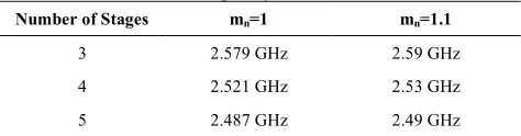
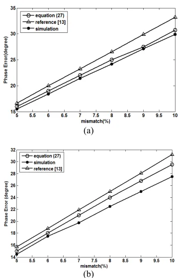
For verifying the extracted equations in this work several simulations performed using 0.18 µm technology in ADS software. For this purpose 3, 4 and 5 stage oscillators is designed. (The results for 2 stage oscillators are discussed in [19] so there is no need to repeat them here.) Note that phase errors in this work were calculated considering different coupling factors so they are potentially more general than previous works but by choosing equal coupling factors the provided results can be compared with other works. Each oscillator is simulated with 2 different coupling factors (mn=1 and mn =1.1) to ensure the equations accuracy and show the effect of coupling factors increase on the phase errors. The simulations are done using 1.8 (V) power supply and
I
bias is considered equal to 1mA. The LC tank in each stage composes of 0.5 pF capacitor and 8 nH inductor and the quality factor (Q) of each tank is equal to 4. All transistors have the same aspect ratio [W/L] of 10[µm]/0.18[µm]. Simulations are performed considering different mismatches in a range of 5% to 10% between first stage's inductor and other inductors of the circuit (the impact of the same amount of capacitor mismatch is identical). Figure 2(a) and (b) show the results for phase error (1
e
y ) in a 3 stage oscillator for mn=1, mn =1.1, respectively. The same condition is provided for 4 and 5 stage oscillators and the results are shown in Figures 3 and 4. As predicted in section 2, phase errors decrease by increasing the coupling factors. The oscillation frequency of the simulated circuits are listed in Table 1.
TABLE 1. Oscillation frequency of the simulated oscillators
Number of Stages mn=1 mn=1.1
3 2.579 GHz 2.59 GHz
4 2.521 GHz 2.53 GHz
5 2.487 GHz 2.49 GHz
It can be seen that by increasing mismatches the simulation and theoretical results are losing their correspondence but they are still in a good conformity. For interpreting this phenomenon we should take a look at Equation (21). As told before the third term in the denominator of Equation (21) is neglected because of the small values for bn and 2
2 tg N p æ ö ç ÷
è ø; but according to
Equation (14) increasing mismatches will increase the
value of xn. So the multiplication of
( ) ( )
2
1
2 n n
tg tg tg
N
p
b - b
æ ö
ç ÷
è ø by xn, which is neglected
approximation used before, loses its accuracy and the theoretical values are resulted. This phenomenon is more obvious in Figure 2 because in 3 stage oscillators the term 2
2
t g N p
æ ö ç ÷
è ø has the greatest value compared to 4 and 5 stage oscillators.
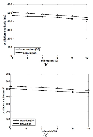
Figure 5 (a), (b) and (c) compares theoretical and simulation results for oscillation amplitude of the first stage versus different mismatches applied to the first stage's inductor in 3, 4 and 5 stage oscillators, respectively. The coupling factors are considered equal to 1. Other parameters are like the previous simulations. The mismatches are applied to the inductor of LC tank but the same results can be extracted if the same percent mismatches are applied to the LC tank capacitor.
(a)
(b)
Figure 2. ye1versus mismatches for (a) mn=1 and (b) 1.1
n
m = in a 3 stage oscillator
(a)
(b)
Figure 3. ye1versus mismatches for (a) mn =1 and (b)
1.1
n
m = in a 4 stage oscillator
(a)
(b)
Figure 4. ye1versus mismatches for (a) mn=1 and (b) 1.1
n
m = in a 5 stage oscillator
(b)
(c)
Figure 5.Oscillation amplitude ( )A1 versus mismatches in (a) 3 stage (b) 4 stage (C) 5 stage oscillator
5.CONCLUDING REMARKS
In this work, we analyzed phase and amplitude of multiphase LC oscillators. We extract closed form equations for calculating phase error and oscillation amplitude in an arbitrary stage number oscillator considering different coupling factors. Not only the generality of the work is increased because of choosing different coupling factors but also the results obtained from the equations are in better conformance with simulations. We show that by increasing coupling factors phase errors can be reduced however it will cause phase noise increase. At last we verify and evaluate the equations by simulating 3 oscillators with different stage numbers.
6. REFERENCES
1. Un, K. F., Mak, P. I. and Martins, R. P., "Analysis and design of open-loop multiphase local-oscillator generator for wireless applications", , IEEE Transactions on Circuits and Systems I: Regular Papers, Vol. 57, No. 5, (2010), 970-981.
2. Hussein, A. and Elmasry, M., "Fractional-n frequency synthesizer for wireless communications", in Circuits and Systems, ISCAS 2002. IEEE International Symposium on, IEEE. Vol. 4, (2002), IV-513-IV-516 .
3. Vassiliou, I., Vavelidis, K., Haralabidis, N., Kyranas, A., Kokolakis, Y., Bouras, S., Kamoulakos, G., Kapnistis, C.,
Kavadias, S., and Kanakaris, N., "A 65 nm cmos multistandard, multiband tv tuner for mobile and multimedia applications",
IEEE Journal of Solid-State Circuits, , Vol. 43, No. 7, (2008), 1522-1533.
4. Kuo, M. C., Kao, S. W., Chen, C. H., Hung, T. S., Shih, Y. S., Yang, T. Y., and Kuo, C. N., "A 1.2 v 114mwdual-band direct-conversion dvb-h tuner in 0.13 m CMOS", IEEE Journal of Solid-state Circuits, Vol. 44, No. 3, (2009), 740-750.
5. Loke, A. and Ali, F., "Direct conversion radio for digital mobile phones-design issues, status, and trends", , IEEE Transactions on Microwave Theory and Techniques, Vol. 50, No. 11, (2002), 2422-2435.
6. Mazzanti, A., Sacchi, E., Andreani, P. and Svelto, F., "Analysis and design of a double-quadrature CMOS VCO for subharmonic mixing at ka-band", IEEE Transactions on Microwave Theory and Techniques, , Vol. 56, No. 2, (2008), 355-363.
7. Lee, K., Park, J., Lee, J. W., Lee, S. W., Huh, H. K., Jeong, D. K., and Kim, W., "A single-chip 2.4-GHz direct-conversion CMOS receiver for wireless local loop using multiphase reduced frequency conversion technique", IEEE Journal of Solid-State Circuits, , Vol. 36, No. 5, (2001), 800-809.
8. Lee, J. and Razavi, B., "A 40-Gb/s clock and data recovery circuit in 0.18-μm cmos technology", IEEE Journal of Solid-State Circuits, Vol. 38, No. 12, (2003), 2181-2190.
9. Maligeorgos, J. P. and Long, J. R., "A low-voltage 5.1-5.8-Ghz image-reject receiver with wide dynamic range", IEEE Journal of Solid-State Circuits, Vol. 35, No. 12, (2000), 1917-1926. 10. Gao, X., Nauta, B. and Klumperink, E., "Advantages of shift
registers over dlls for flexible low jitter multiphase clock generation", IEEE Transactions on Circuits and Systems II: Express Briefs, Vol. 55, No. 3, (2008), 244-248.
11. Maneatis, J. G. and Horowitz, M. A., "Precise delay generation using coupled oscillators", IEEE Journal of Solid-State Circuits, Vol. 28, No. 12, (1993), 1273-1282.
12. Kinget, P., Melville, R., Long, D. and Gopinathan, V., "An injection-locking scheme for precision quadrature generation",
IEEE Journal of Solid-State Circuits, , Vol. 37, No. 7, (2002), 845-851.
13. Romanò, L., Levantino, S., Samori, C. and Lacaita, A. L., "Multiphase lc oscillators", IEEE Transactions on Circuits and Systems I: Regular Papers, Vol. 53, No. 7, (2006), 1579-1588. 14. Kim, J. J. and Kim, B., "A low-phase-noise CMOS lc oscillator
with a ring structure", in Solid-State Circuits Conference, Digest of Technical Papers. ISSCC. 2000 IEEE International, (2000), 430-431, 475.
15. Geng, X. and Dai, F. F., "An x-band transformer-coupled varactor-less quadrature current-controlled oscillator in 0.18",
IEEE Journal of Solid-State Circuits, Vol. 45, No. 9, (2010), 1669-1677.
16. Cho, L. C., Lee, C. and Liu, S., "A 1.2-V 37-38.5-GHz eight-phase clock generator in 0.13-um CMOS technology", IEEE Journal of Solid State Circuits, (2007), 1261-1270.
17. Mazzanti, A., Svelto, F. and Andreani, P., "On the amplitude and phase errors of quadrature lc-tank CMOS oscillators", IEEE Journal of Solid-State Circuits, Vol. 41, No. 6, (2006), 1305-1313.
18. Mirzaei, A., Heidari, M. E., Bagheri, R., Chehrazi, S. and Abidi, A. A., "The quadrature lc oscillator: A complete portrait based on injection locking", IEEE Journal of Solid-State Circuits, Vol. 42, No. 9, (2007), 1916-1932.
19. Ghonoodi, H. and Miar Naimi, H., "Canceling tradeoff between phase noise and phase error in parallel coupled quadrature oscillators", in Electrical Engineering (ICEE), 2010 18th Iranian Conference on, IEEE, (2010), 459-464.
APPENDIX A
Calculation of the Phase of Current Injected to LC Tanks
As told before In+ can be found by Equations (6) and (7). Phasor diagram for I1+ according to Equation (6) is
shown in Figure 6 (the term 2Ibias
p is neglected).
Using Figure 6, the phase of I1+ can be found by Equation (A1):
(
)
1 1 1 1
I+ p q a
Ð = + - + W (A1)
whereW1 can be found as Equation (A2):
(
1)
1
2 N p- q -q
W = (A2)
Considering the fact that N 1
N
p
q - » -q p , for finding a1
, Equation (A3) can be written:
( ) ( )
( )
1 1
1 2
2 2 1
1 sin
1 1 1 2 cos( )
m tg F
tg F N
a
p p
-=
+
+ + - (A3)
Equation (A4) can be extracted immediately considering Figure 6:
1
1 2
1
1 cos 1
( )
sin
m
AD N
tg F F
AF m
N
p g p
+ +
+ = = (A4)
As shown in Equation (A4), the value of tg F F( 1+ 2)is defined as
g
.Using Equations (A3) and (A4) considering
2 2
F N
p p
» - ,
Equation (A5) can be extracted:
( 1 )
1 2
1 1
1 cos( ) 2
sin
2 cos 1
m
N
m m
N
p a
p
-»
æ ö
+ ç ÷+
è ø
(A5)
Use of the same approach for other stages will lead to the same equation. So assuming small values for
a
n , Equation (A6) can be extracted for the nth stage.( )
2
1 cos( ) 2 2 cos 1
n n
n n
m
N
m m
N
p a
p
-»
æ ö
+ ç ÷+
è ø
(A6)
The parameter an relates the output phase of a stage to the value of current passing through its tank which means by changing coupling factors one can change an
(through Equation (A6)) and according to Equations (6) and (7) the output phase would change either. Therefore, an can be considered as the effect of coupling factors on the output phase. Figure 7 shows the dependency betweenan and mn in a 3 stage oscillator.
Figure 6. Phasor diagram of (6) without considering the term 2
Ibias
p
Figure 7.an versus mn in a 3 stage oscillator
Analysis of Oscillation Amplitude and Phase Error in Multiphase LC Oscillators
S. Seifi, H.Miar-Naimi
Department of Electrical Engineering, Babol University of Technology, Iran
P A P E R I N F O
Paper history:
Received 30 September 2012
Received in revised form 30 December 2012 Accepted 24 January 2013
Keywords:
Coupling Factors Fabrication Mismatches Multiphase LC Oscillators Phase Errors
Wireless Communications
هﺪﯿﮑﭼ
ا
ﯾ ﺪﺑشوررﺎﮐﻦ ﯾ
ياﺮﺑارﯽﻌ ﯾ ﻪﻨﻣادوزﺎﻓيﺎﻄﺧﻦﺘﻓﺎ نﺎﺳﻮﻧردﯽﺟوﺮﺧژﺎﺘﻟوي
هزﺎﻓﺪﻨﭼيﺎﻫزﺎﺳ ي
LC ﯽﻣﻪﺋارا ﺪﻨﮐ
.
ياﺮﺑ
ﯾ ﻪﻄﺑارﻦﺘﻓﺎ ﻣي ﯿ ﺮﺿوﯽﺟوﺮﺧزﺎﻓنﺎ ﯾ
زاﻪﻘﺒﻃﺮﻫژﻼﭘﻮﮐﺐ ﯾ
ورﮏ ﯾ ردﺮﮑ ﯾ ﻌﻣﺎﺟياﺮﺑوهﺪﺷهدﺎﻔﺘﺳاﯽﺿﺎ ﯿ
ﺑﺖ ﯿ ﻠﺤﺗﺮﺘﺸ ﯿ ﻞ
ﺮﺿﻪﻘﺒﻃﺮﻫياﺮﺑ،هﺪﺷمﺎﺠﻧا ﯾ
ﺖﺳاهﺪﺷﻪﺘﻓﺮﮔﺮﻈﻧردﯽﺗوﺎﻔﺘﻣژﻼﭘﻮﮐﺐ
.
ﮏﻧﺎﺗردﻖﺑﺎﻄﺗمﺪﻋﻪﻣادارد LC
ﻪﺑﻒﻠﺘﺨﻣتﺎﻘﺒﻃ
ﺎﺒﻗﺎﻌﺘﻣوهﺪﺷضﺮﻓزﺎﻓيﺎﻄﺧﯽﻠﺻاﻊﺒﻨﻣناﻮﻨﻋ هﺪﺷﻪﺒﺳﺎﺤﻣﻪﻧﺎﮔاﺪﺟرﻮﻃﻪﺑﻪﻘﺒﻃﺮﻫزﺎﻓيﺎﻄﺧ
ﺖﺳا
.
ﻪﻨﻣادﺲﭙﺳ ژﺎﺘﻟوي
ﺎﺑدﺮﻓﻪﺑﺮﺼﺤﻨﻣرﻮﻃﻪﺑﻪﻘﺒﻃﺮﻫﯽﺟوﺮﺧ ﺎﺘﻧﮏﻤﮐ
ﯾ ﻪﺑزﺎﻓيﺎﻄﺧﺞ ﺖﺳاهﺪﻣآﺖﺳد
.
ﻪﻧ اﺮﺿﻦﺘﻓﺮﮔﺮﻈﻧردﺎﻬﻨﺗ ﯾ
ژﻼﭘﻮﮐﺐ
ﻌﻣﺎﺟتوﺎﻔﺘﻣ ﯿ
اﺰﻓااررﺎﮐﺖ ﯾ
ﺎﺘﻧﻪﮑﻠﺑهدادﺶ ﯾ
ﻪﺑﺞ اردهﺪﻣآﺖﺳد ﯾ
ﺑﻖﺑﺎﻄﺗﯽﻠﺒﻗيﺎﻫرﺎﮐﻪﺑﺖﺒﺴﻧرﺎﮐﻦ ﯿ
ﺒﺷﺎﺑيﺮﺘﺸ ﯿﻪ يزﺎﺳ ﺎﻫ
دراد
.
ﺎﺘﻧ ﯾ ﻪﺑيرﻮﺌﺗﺞ ﺒﺷﮏﻤﮐﻪﺑهﺪﻣآﺖﺳد ﯿﻪ
يزﺎﺳ مﺮﻧرددﺪﻌﺘﻣيﺎﻫ راﺰﻓا
ADS نآﺖﺤﺻوﯽﺳرﺮﺑ ﺎﺗﺎﻫ
ﯿﯾ ﺖﺳاﻪﺘﺸﮔﺪ
.
![Figure 1. Multiphase LC oscillator (a) circuit schematic diagram [13] and (b) block diagram](https://thumb-us.123doks.com/thumbv2/123dok_us/236171.2018273/2.595.86.509.533.733/figure-multiphase-oscillator-circuit-schematic-diagram-block-diagram.webp)