A b s t r a c t. The paper presents selected results and discussion of model investigations of horizontal silo pressure distribution during eccentric discharging for an outlet located in the lower part of a silo wall conducted at the Bia³ystok University of Technology using a ferrocement circular silo model. Tests were conducted using white mustard seeds were used as the agricultural bulk solid. Pressure were measured using a system of embedded pressure cells. The model studies revealed dynamic characteristics of eccen-tric pressure changes. Results were compared with the theoretical bulk solid pressures calculated on the basis of Eurocode 1 provi-sions. The results of these studies confirmed that a non-uniform distribution of discharge pressures occured in the silo wall in the very early stages of the eccentric discharging process. Conti-nuation of eccentric discharge leads to a more uniform pressure distribution.
K e y w o r d s: agricultural bulk solids, pressure, eccentric discharging, silo
INTRODUCTION
Eccentric discharge occurs in silos when the silo bottom outlet is located at any eccentricity from the centre of gravity of silo bin cross-section. For such a case the bulk solid flow channel during discharge forms eccentrically to the vertical axis of the silo bin and moves to the internal surface of the silo wall. In many cases this phenomena is thought to be the reason for a significant redistribution of horizontal bulk solid pressure at the silo wall height and along the silo wall perimeter. In some cases this type discharge condition can create pressure distributions which cause serious damage to the silo structure, as firstly reported Jenike (1967).
Some of the first detailed experimental studies on the eccentric silo unloading were performed by Pieper and Wagner (1968) in Germany using silo model. Since then, many other researchers have tried to precisely measure the bulk solid pressure on silo walls during eccentric dischar-ging eg Reimbert and Reimbert (1980), Wood (1983), Hamdy (1991), Molendaet al. (2000) and many others. Investi-gations have also been performed ‘in-situ’ on full-scale ec-centrically unloaded silos storing cementegHamdy (1991) and grain (£apko and Wójcik, 2004). However, the results of these studies have shown large amounts of variation depend-ing not only on eccentricity but many others factors, as well.
Eccentric unloading in silos is an important design factor which must be taken into account. Eccentric un-loading causes the redistribution of vertical and horizontal forces in the silo and produces bending moments in the cylindrical silo wall cross-sections, which should be taken into account by numerical analysis (Guaita et al., 2003; £apko and Prusiel, 2004; £apko and Wójcik, 2004).
Based on experimental model studies as well as investi-gation on real silo structures some idealized models for eva-luation of eccentric pressure distribution have been presen-ted in the last two decades (Martens, 1988; Safarian, 2001). Some of these propositions have been introduced into a few national Silo Codes (DIN 1055, 1987; AS 3774, 1996; PN-B-03262, 2002) and finally introduced into Eurocode 1 (EN 1991-4, 2006). In the European Silo Standard a non-uniform load distribution is specified on the silo wall perimeter for silos which discharge eccentrically. The load distribution is a function of reliability class of structure (called here Action Assessment Class) depending on the silo bin slenderness, its capacity and the eccentricity of the discharge outlet.
Pressure of agricultural bulk solids under eccentric discharging
of cylindrical concrete silo bin*
A. £apko
Faculty of Civil and Environmental Engineering, Bia³ystok University of Technology, Wiejska 45, 15-351 Bia³ystok, Poland
Received November 13, 2009; accepted December 20, 2009
© 2010 Institute of Agrophysics, Polish Academy of Sciences
Corresponding author’s e-mail: lapko@pb.bialystok.pl
*This work was supported by the State Committee for Scientific Research, Poland, under framework of Rector’s Project No. W/WBIŒ/13/06.
A
A
Agggrrroooppphhyhyysssiiicccsss
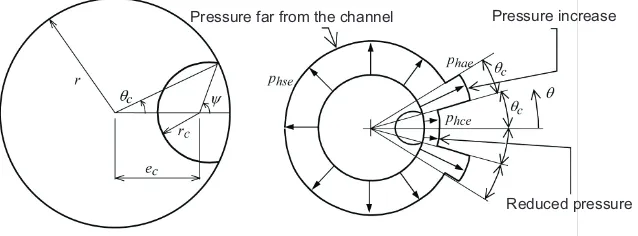
According to Eurocode 1 (2006) the idealized model of eccentric pressure is governed by the bulk and the solid flow channel eccentricityec. The standard distribution is shown
in Fig.1 consisting of the high channel edge pressurePhaein the zone adjacent to the flow channel, the decreased pressure Phcein the flowing zone and the static pressurePhsefar from the flowing channel. The standard design procedure is intended to identify conditions that are the most demanding for each silo geometry and structural arrangement. The flow channel is assumed to be a circular arch with the location and radius of the flow channel based on a minimization of the total frictional drag at the channel perimeter of the solid in the channel.
Experimental studies were performed using agriculture bulk solids at Bia³ystok University of Technology to assess the Eurocode provisions concerning the minimum and maxi-mum pressures in eccentrically unloaded silos. These studies are an extension of previous studies done by £apko and Konopacki (2001).
Experimental studies were conducted in both cylindri-cal silo models as well as in real grain silos equipped with eccentric outlets. The results are presented and discussed herein showing the dynamic characteristics and time depen-dent redistribution of bulk solid pressure due to eccentric discharging process. The experimentally measured pressu-res were compared with appropriate theoretical values based on Eurocode 1 (2006) procedures for silo structures classi-fied into the Action Assessment Class No. 3.
EXPERIMENTAL MODELLING OF LATERAL ECCENTRIC PRESSURE
Model investigation on lateral silo pressure during ec-centric discharging were conducted at the Faculty of Civil and Environmetal Engineering of Bia³ystok University of Technology on a large ferrocement cylindrical silo bin model (total height H= 2500 mm, diameter D = 800 mm and wall thickness t =14 mm), arranged on a separate stand (£apko and Konopacki, 2006). Silo wall pressure were measured using a system of embedded pressure cells. The silo was equipped with an eccentric silo discharge outlet
located in the side wall of the model silo (e
0equal to the radius of the cross-section of the silo model,e0=0.5D). Tests were conducted using white mustard seeds whose properties are given in Table 1.
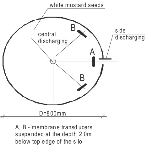
Horizontal pressures caused by the particulate solid were measured during both filling and eccentric discharge of the silo bin model using originally designed pressure disc cells suspended inside the bulk solids in the bin model. The cells were positioned at a depth of 20 cm above the level of the discharge outlet. The locations of the cells in the silo bin cross-section are shown in Fig. 2. The pressures cells were located to measure the theoretical maximum and minimum horizontal pressures predicted by Eurocode 1 (2006). Pressure cell A was located within the flow channel (minimum pres-sure) while pressure cells B – were located near the flow channel edges (in the zone of maximum pressure).
A detailed view of the lower part of ferrocement silo bin model and of the embedded pressure cell are shown in Fig.3. The wireless computerized measurement system was pre-viously used to measure pressure values in bins, described in the paper by £apko and Ko³³¹taj (2003).
Filling of the model bin required approximately 40 min while discharging of the bin required approximately 35 min. Pressure readings were measured from each load cells du-ring both loading and unloading of the model bin. Pressure readings were converted into horizontal pressures by a compu-ter. Selected diagrams of horizontal pressure registrations against time during filling and discharging are presented in Fig. 4a (for the first filling-discharging cycle) and in Fig. 4b (for the second similar cycle).
Pressure far from the channel Pressure increase
Reduced pressure
Fig. 1.Flow channel during eccentric discharging of silo bin and pressure distribution on silo bin perimeter according to Eurocode 1.
Property Mustard seeds
Effective friction angle (°) 27
Bulk density (kN m-3) 7.30
Colour white
Particle diameter (mm) 1¸2
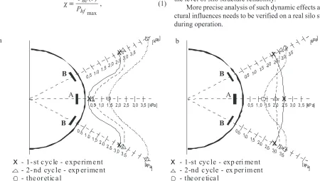
Horizontal pressures during the initial stages of eccentric discharge (1 min after the start of discharge) are shown in Fig. 5a for pressure cell A (located in the flow channel) and for pressure cells B (two cells which were located outside of the flow channel). The pressures within the flow channel were significantly smaller than those on the edge of the flow channel (pressure A/pressure B = 0.17). In Fig. 5b are shown the pressures measured (20 min after the start of discharge).The pressures measured within the flow channel were still smaller than those measured outside of the flow channel however the pressure differences between the two locations are not quite as significant (pressure A/ pressure B = 0.33). Pressures values predicted using the
B
A
D=8 00mm
white mustard seeds
central discharging
side discharging
A, B - memb ran e transd ucers suspe nded at the dep th 2,0m below top e dge of the silo
B
Fig. 2.Cross-section of silo bin model showing location of cells and position of side outlet.
1
2 3
Fig. 3.View of silo model with side outlet and embedded cell de-tails: 1 – membrane, 2 – base, 3 – wire.
Wys yp b ocz n y 26-01 -2006
-0,500 0,000 0,500 1,000 1,500 2,000 2,500 3,000
9:50: 24 10:04:48 10:19:12 10:33:36 10: 48:00 11: 02: 24 11: 16: 48 11: 31: 12 11:45: 36
czas [gg:m m:ss]
ci
S
n
ie
n
ie
[k
P
a
]
cz uj nik A cz uj nik B opró¿niani e
nape³nianie
eccentricdischarging
filling discharging
sensor B
pr es su re [k P a]
time [hh:mm:ss]
sensor A
Wysyp boc zny 26-01 -2006
-0, 500 0, 000 0, 500 1, 000 1, 500 2, 000 2, 500 3, 000 3, 500
11: 50:27 12: 04:51 12:19:15 12:33:39 12:48: 03 13: 02: 27
czas [gg:mm:ss]
c
iS
n
ie
ni
e
[k
P
a
]
cz ujnik A cz ujnik B opró¿nianie
nape³nianiefilling discharging
sensor A sensor B
pr es su re [k P a]
time [hh: mm:ss]
Fig. 4.Changes of pressure during filling and discharging phases of the silo model filled with white mustard seeds: a – for cycle 1, b – for cycle 2.
Pressure
(kPa)
Pressure
(kPa)
a
b
design procedures described in Euocode 1 (Silo Action Assessment Class 3) are shown in both Figs 5a and 5b. The pressure distribution predicted by Eurocode 1 matched clo-sely the shape of the pressures observed immediately after discharge started (Fig. 5a). Euorcode 1 did not predict as well the pressure distribution observed during the advanced stages of eccentric discharge (Fig. 5b). For this condition a more uniform distribution of pressure was observed.
Bulk solid pressure diagrams shown in Fig. 4a,b during eccentric discharging revealed visible dynamic characteri-stics. Dynamic effects on silo wall structure can be described for design purposes by dynamic coefficients. In a given time of eccentric pressure the static horizontal loads on the silo bin wall may be converted into dynamic values using a dy-namic coefficientc, expressed as the ratio:
c = P t
P
he
hf
( )
max
, (1)
where: Phe(t) – horizontal dynamic values of pressure
measured at a given timetduring eccentric discharging of the silo bin model, Phf max – horizontal static pressure
measured after the end of the filling process.
The time dependent changes of dynamic coefficients cal-culated as mean values from two test cycles during eccentric discharging through the side outlet are presented in Fig. 6.
In the initial phase of eccentric discharging, the value of coefficient computed on the basis of cell A measurements (in the flow channel) wasc= 0.11, whereas the same
coef-ficient computed from the registration using cells B (outside the flow channel) werec= 1.78 some 16 times larger.
The results of model tests indicating the dynamic bulk solids pressure characteristic revealed the possibility of fati-gue effects in silo wall structure which may strong influence the level of silo structure reliability.
More precise analysis of such dynamic effects and stru-ctural influences needs to be verified on a real silo structure during operation.
0, 5 1,0 1, 5 2,0 2,5 3, 0 3,5 [ kPa]
x
x
x
x
- 1- st c yc le - e xpe rim e nt - 2- nd cyc le - exp er ime nt - the or etic a l
A B
B
x
x
x
x
- 1-st cyc le - exp eri me nt - 2-nd c ycle - ex per im ent - the or e tica l
A B
B
0,5 1,01,5
2,0 2,53,0
3,5
[kPa] 0,51,0
1,52,0 2,53,0
3,5
[ kPa]
0,5 1, 0 1, 5 2,0 2, 5 3,0 3, 5 [kP a]
0,5 1,0 1,5
2,0 2,53,0
3,5
[ kPa] 0,51,0
1,52,0 2,5 3,0
3,5
[kPa]
Fig. 5.Comparison of experimental and theoretical lateral pressure values predicted for eccentric discharging of the silo model: a – 1 min after opening of outlet , b – 20 min after.
Ws pó³cz ynnik dy nam icz ny
-0, 400 -0, 200 0, 000 0, 200 0, 400 0, 600 0, 800 1, 000 1, 200 1, 400 1, 600 1, 800 2, 000
0 100 200 300 400 500 600 700 800 900 1000 1100 1200 1300 1400 1500 1600 1700 1800 1900 2000 2100 2200 2300
cz as [s]
w
a
rt
o
S
æ
w
s
p
ó
³c
zy
n
n
ik
a
d
y
n
a
m
ic
zn
e
g
o
c z ujnik A c z ujnik Bsensor B
time [s]
sensor A
d yn am ic co ef fi ci en t
Fig. 6.Changes of dynamic pressure coefficient during discharging process for silo model filled with white mustard seeds.
Dynamic
coefficient
Time (s)
DYNAMIC EFFECTS OF ECCENTRIC PRESSURE IN REAL SILO
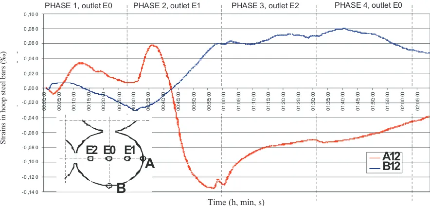
Tests were conducted in a full-scale grain elevator in Poland to determine the dynamic pressure effects during eccentric unloading. The reinforced concrete silo was 8.00 m in diameter and 29.5 m tall and was part of a grouped silo. The silo was equipped with one centric and two eccentric outlets located in the center region of the silo as shown in Fig. 7. Strains were measured using electric resistance strain gages attached to the circumferential reinforcement in the silo wall. The strain gages were located 12.0 m above the floor of the silo on lines A and B as shown in Fig. 7.
The measurements of strains in wall structure were conducted in the initial phase of discharging, lasting for 120 min, immediately after the end of the process of silo filling with grain. In the tests a wireless computer system was used.
Strains were measured using a wireless computer sys-tem. Strains were monitored during four different phases of discharge with each phase lasting approximately 30 min. Discharging of the silo started immediately after filling of the silo ended. The four different phases of discharge were: 1. central outlet E0,
2. eccentric outlet E1 (close to the location of gauges), 3. eccentric outlet E2 (opposite to the location of gauges), 4. repeated discharging by central outlet E0.
Significant redistribution of horizontal strains within the reinforcing steel were observed during phase E1 (dis-charging closer to line A) in which eccentric unloading of the bin occurred. During this phase a non-uniform horizon-tal pressure distribution was observed around the wall
perimeter with similar dynamic overpressures observed in both the real and model bin. These results validated the pressure distribution model given in Eurocode 1 (2006).
CONCLUSIONS
1. Experimental studies concerning eccentric silo bin pressures conducted in cylindrical silo bin models confir-med that a non-uniform horizontal pressure distribution oc-curs around the wall perimeter, similar to that proposed for design in Eurocode 1. However, this non-uniform pressure tribution only occurred during the initial phases of the dis-charging process. In the advanced stage of eccentric dischar-ge the pressure distribution had a different, more symmetric shape, with strong increased pressures in the flow channel. 2. Dynamic overpressures were measured during ec-centric discharge with the magnitude of these dynamic overpressures varying depending on the location of the pressure measurement and the period of discharging. The maximum dynamic overpressure value of 1.78 was measu-red during the initial stages of discharge and was located outside of the flow channel, whereas in the zone of flow channel its value was equal to 0.11 only.
3. In full scale tests conducted in real grain silos, redistribution of strains and stresses (the cause of bending moments in the silo wall) were observed in the silo wall closet to the eccentric flow channel during the initial stages of eccentric discharging. During discharge stains were measured in the silo wall that appeared to produce dynamic characteristics within the structure which could affect the silo structure reliability.
-0 ,14 0 -0 ,12 0 -0 ,10 0 -0 ,08 0 -0 ,06 0 -0 ,04 0 -0 ,02 0 0 ,00 0 0 ,02 0 0 ,04 0 0 ,06 0 0 ,08 0 0 ,10 0
0 0 :0 0: 00 0 0 :0 5: 00 0 0 :1 0: 00 0 0 :1 5: 00 0 0 :2 0: 00 0 0 :2 5: 00 0 0 :3 0: 00 0 0 :3 5: 00 0 0 :4 0: 00 0 0 :4 5: 00 0 0 :5 0: 00 0 0 :5 5: 00 0 1 :0 0: 00 0 1 :0 5: 00 0 1 :1 0: 00 0 1 :1 5: 00 0 1 :2 0: 00 0 1 :2 5: 00 0 1 :3 0: 00 0 1 :3 5: 00 0 1 :4 0: 00 0 1 :4 5: 00 0 1 :5 0: 00 0 1 :5 5: 00 0 2 :0 0: 00 0 2 :0 5: 00
T im e [ g g : m m : s s ]
S tr a in s in h o o p s te e l b a rs [0 ] A1 2 C 1 2
P HA S E 1 , ou tle t E0 P H A SE 2 , ou tl et E 1 P HA SE 3, ou tl et E 2 P HA SE 4, ou tl et E 0
A
B
E1
E0
E2
A12
B12
Fig. 7.Strain changes in the real grain silo wall structure due to different modes of discharging.
Strains in hoop steel bars (‰)
Time (h, min, s)
REFERENCES
AS 3774-1996, Australian Standard,1996.Loads on Bulk Solids
Containers. Melbourne, Australia.
DIN 1055,1987.Lastannahmen fur Bauten. Lasten in Silozellen. German Standard, Berlin, Germany.
Eurocode 1, EN 1991-4,2006.Actions on structures. – Part 4: Silos and Tanks. Brussels, Belgium.
Guaita M., Couto A., and Ayuga F., 2003.Numerical simulation of wall pressure during discharge of granular material from cylindical silos with eccentric hoppers. Biosys. Eng., 85(1), 101-109.
Hamdy Hessien Abd-el-rahim, 1991.Exprimental and theore-tical analysis of dynamic effects in cement storage silos. Ph. D. Thesis, Wroc³aw Technical University, Wroc³aw, Poland.
Jenike A.W., 1967. Denting of circular bins with eccentric drawpoints. J. Struc. Div. Proc. ASCE, 27-35.
£apko A. and Ko³³¹taj J., 2003.The wireless technique of exami-nation of silo wall structures during operation. Proc. 4th Int. Conf. Conveying and Handling of Particulate Solids. May 27-30, Budapest, Hungary.
£apko A. and Konopacki W., 2001.Redistribution of stress state in cylindrical silos with eccentric emptying (in Polish). Sci. J. Wroc³aw Academy of Agriculture, 419, 251-262.
£apko A. and Konopacki W., 2006.Bulk solids pressure effects due to eccentric discharging of circular silo bin. Proc. 5th Int.
Conf. Conveying and Handling of Particulate Solids. August 27-31, Sorrento, Italy.
£apko A. and Prusiel J., 2004.Structural analysis of R C circular grouped silos under patch actions. Granular Matter J., 6(2-3), 185-190.
£apko A. and Wójcik R., 2004.Analysis of eccentric effects on stress states in cylindrical silo bins for grains (in Polish). Acta Agrophysica, 4(2), 393-405.
Martens P., 1988.Silo Handbuch. Ernst Press, Berlin, Germany. Molenda M., Horabik J., Thompson S.A., and Ross I.J., 2000. Nonsymmetrical pressure due to eccentric filling and emptying of grain silos (in Polish). Proc. 11th Conf. Reinforced and Prestressed Silos and Water Tanks. October 18-21, Œwieradów Zdrój, Poland.
Pieper K. and Wagner K., 1968.Der Einfluss Verschiedener Auslaufarten auf die Seitendrucke in Silozellen. Aufbereitung-Technik, 10, 542-546.
PN-B-03262,2002.Polish Silo Code (in Polish). Warsaw, Poland. Reimbert M. and Reimbert A., 1980.Pressures and
overpres-sures in vertical and horizontal silos. Proc. Conf. Design Silos for Strength and Flow, September 2-4, Lancaster, UK. Safarian S.S., 2001. Empirical method for computing bending
moments in circular silo walls due to assymetric flow considering flow channel concept. Bulk Solid Handling, 21, 3/4, 153-155.