i tif c n e C i o c n S f l e a r n e o n i c t e
a 2
nr 0
et 1
1
n I
ISC 2011
Proceeding of the International Conference on Advanced Science,
Engineering and Information Technology 2011
Hotel Equatorial Bangi-Putrajaya, Malaysia, 14 - 15 January 2011
ISBN 978-983-42366-4-9
ISC 2011
International Conference on Advanced Science, Engineering and Information Technology ICASEIT 2011
Cutting Edge Sciences for Future Sustainability Hotel Equatorial Bangi-Putrajaya, Malaysia, 14 - 15 January 2011
SR
IE AV IUN IT
NI
ESE
D K
O B
IN N
R AG
JA A L S A A E N P M N A A L U A T Y A S
S A I
REP
N I
NOI TAI COSSA STNEDUTS NA ISENOD
Organized by Indonesian Students Association Universiti Kebangsaan Malaysia Proceeding of the
Application of Artificial Intelligent For Armour
Vehicle Detection Using Digital Image Processing
For Aerial Application
Kamaruddin Abd Ghani, Hafizan YosriDepartment of Electrical & Electronic Engineering, National Defence University of Malaysia Kem Sungai Besi, Kuala Lumpur, 57000, Malaysia
Tel.:+60360752728, E-mail:[email protected], [email protected]
Abstract—This paper will presents a new automatic target recognition (ATR) algorithm to detect targets such as battle
tanks and armoured personal carriers especially that been used by Malaysia Armed Forces from air-to- ground scenario. Numerous friendly-fire incidents justify the need for identification of armour vehicle in both command control and weapon systems. Rapid and reliable identification of the targets at maximum surveillance is a challenging problem. In this paper work, the reliable method to segregate the potential target from the background scene such as Fourier Transform is applied before the extracted target will be process in order to get the detail of edges and boundaries using Hough Transform. The edges will provide sufficient information for the system to generate training data for Artificial Neural Network simulation to recognize the potential target image.
Keywords— Automatic Target Recognition; Artificial Neural Network; Fourier Transform; Hough Transform
I. INTRODUCTION
Automatic target recognition (ATR), which has been referred to as weapon vision, is one of the challenging problems of the defence industry. The aim of an ATR system is to remove the role of man from the process of target detection and recognition and hence, implementing a real-time and reliable system of high performance. Automatic Target Recognition (ATR) is concerned with the detection, tracking and recognition of a targets using input data obtained from a multitude of sensor types such as forward looking infrared (FLIR), synthetic aperture radar (SAR) and laser radar (LADAR). The automatic target recognition (ATR) term originated from the Low Altitude Navigation and Targeting Infrared for Night (LANTIRN) program in the early1980’s.
Currently ATR methods are not fully automatic, relying instead on a partnership between computer processing and human analysis. Although computer algorithms accomplish much preliminary ATR work of sifting through millions of data pixels per image to identify candidate targets, image analysts play a crucial role in the recognition process by reviewing the ATR algorithm results.
For example, by using the ATR, it will annotates image areas containing potential targets with target cues for the image analysts, who use visualization tools provided by the ATR human-computer interface to establish the true target types and produce a target report to pass to the battlefield commander.[1]
II. AUTOMATIC TARGET RECOGNITON
Fig. 1 Methodology chart for Automatic Target Recognition
A. Fourier Transform
Edge detection is one of the major image- processing requirements for achieving automatic target recognition. Edge detecting an image significantly reduces the amount of data and filters out useless information, while preserving the important structural properties in an image. This method is one of the major image-processing requirements for achieving efficient and accurate target recognition in difficult domains. [3]
The Fourier transform is a representation of an image as a sum of complex exponentials of varying magnitudes, frequencies, and phases. The Fourier transform plays a critical role in a broad range of image processing applications, including enhancement, analysis, restoration, and compression.
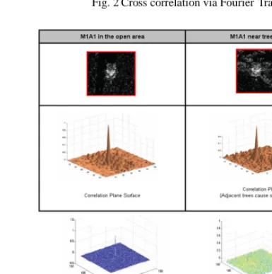
The Fourier transform can also be used to perform correlation, which is closely related to convolution. Correlation can be used to locate features within an image; in this context correlation is often called template matching The cross- correlation between the reference and test images for all possible shifts can be defined as per below:
(1)
When the target scene matches the reference image exactly, output is the auto correlation of the reference image. If the input r(x) contains a shifted version s(x-x0) of the reference signal, the correlation will exhibit a peak at x=x0. If the input does not contain the reference signal s(x), the correlation output will be low. If the input contains multiple replicas of the reference signal, resulting cross-correlation contains multiple peak sat locations corresponding to input positions [4]
Fig. 2 Cross correlation via Fourier Transform
Fig. 3 Fundamental of ATR System Using Correlation for Battle Tank Detection
B. Hough Transform
The Hough function implements the Standard Hough
Transform (SHT). The SHT uses the parametric
representation of a line:
(2)
The variable rho is the distance from the origin to the line along a vector perpendicular to the line. Theta is the angle between the x- axis and this vector. The Hough function generates a parameter space matrix whose rows and columns correspond to rho and theta values respectively. Peak values in this space represent potential lines in the input image.
Fig. 4 The fundamental figure of Hough Transform
C. Artificial Neural Network
One main requirement towards ATR implementation is the need to store a model database before recognition can proceed. The model database can be constructed from either a CAD model or from a real image set.
The new model is then compared with the remaining models as above, and the process is repeated until all of the models belong to a single hierarchically constructed model tree. To perform this operation, target position detection and target classification shall be done using neural networks. [5]
Artificial neural network is one of these learning based methods that is based on the learning theory. The idea of artificial network was originally inspired of the neural networks in the human brain. Although an accurate definition does not exist, a learning process in an artificial neural network (ANN) context can be viewed as the problem of updating the network architecture and connection weights so that a network can perform well a specific task.
The ANN must learn the connection weights from an available set of training patterns. The performance improves overtime by iteratively updating the weights in the network. Instead of following a set of rules like case based reasoning systems, the ANNs learn what is underlying the rules using the learning algorithm. It is the procedure that describes the way in which a set of learning rules are used to adjust the connection weights.
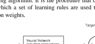
Fig. 5 Structure of Feed Forward Neural Network
The Artificial Neural Network that have constructed is three-feed forward neural network based on BP (Back Propagation) algorithm is proposed. The detail as shown in figure below.
When the feed forward neural network is being learned, the account of net in the hidden layer is adjusted until the network is convergent [6]. The detailed steps are as follows:
1. To initialize the network 2. To input mode of learn
3. To calculate the output of the hidden layer 4. To calculate the output of the output layer
5. To calculate the error of the output layer
6. To judge the error is convergent or not, if it is convergent then the training isstopped,or go to the next step
7. To adjust the weight of connection between the interlayer and the output layer and biased value of the unit in the interlayer
8. To adjust the weight of connection between the interlayer and the input layer and biased value of the unit in the interlayer
9. To update the mode of learning
10. If the mode of learning is over go to step 12, or update the account of learning.
11. If the account of learning has not exceeded the upper limit go to step 2, or go to the next step. 12. Training is over, and the network is not convergent.
After the network is trained successfully the weights of the network are saved, and will be used for recognizing the unknown target.
Fig. 7 Structure of three layer feed forward neural network
III. THEPROPOSEDTARGETDETECTIONMETHOD
This research paper will concentrate on the image that taken by aerial vehicle unit which will be view the image from 90º position. Since this research still undergo, the actual sample image still under collection process and had been replaced with another sample to prove the reliability and effectiveness of the proposed method.
Fig. 9 Flow chart for automatic target recognition for armour vehicle using digital image processing for aerial application
A. Cross Correlation Using Fourier Transform
Fig. 10 Cross correlation method using Fourier Transform simulation using MATLAB Software
Fig. 11 The Overlay window
The Overlay window shows the locations of the targets by highlighting them with rectangular regions of interest (ROIs). These ROIs are present only when the targets are detected in the video frame
Fig. 12 The cross correlation windows
The Cross-correlation window shows the result of cross-correlating the target template with a video frame. Large values in this window correspond to the locations of the targets in the input image. The windows displays an M- by-N matrix input by mapping the matrix element values to a specified range of colors .The display is updated as each new input is received. This block treats a length M 1-D vector input as an M-by- 1 matrix.
Fig. 13 Match metric
The Match metric window shows the variation of the target match metrics. The model determines that the target template is present in a video frame when the match metric exceeds a threshold (cyan line).
B. Edge And Boundaries Detection Using Hough Transform
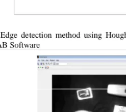
Fig. 14 Edge detection method using Hough Transform simulation using MATLAB Software
Fig. 16 Example of image produced from the simulation
The binary image produced from the simulation will be used during neural network simulation
C. Image recognition using Feed Forward Neural Network
Fig. 17 The feed forward neural network
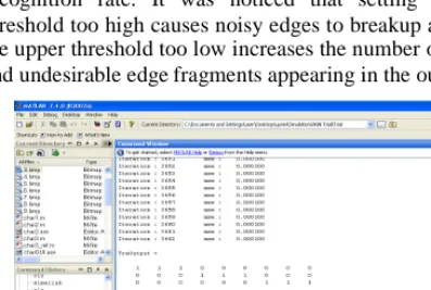
The feed forward neural network will used the binary data from the Hough Transform simulation to generate the component vector value. This vector value will be used as input data for neural network simulation. At this stage, all the related parameter of the network such as the threshold value must be best correctly to get the best result of recognition rate. It was noticed that setting the lower threshold too high causes noisy edges to breakup and setting the upper threshold too low increases the number of spurious and undesirable edge fragments appearing in the output. [5]
Fig. 18 The result of recognition rate from feed forward neural network simulation
Finally, the input data will be compared with the Target Data to determine the recognition rate. The recognition rate or
correct classification rate (CCR %) between input and target image is measured as follows,
(3)
where c is the total number of correctly classified images andtis the total number of classified images.
IV. EXPERIMENTALRESULTS
Currently the simulation is done by using the sample image and shows the positive result of the recognition rate. The next step is to collect the actual image of the armour vehicle and running the simulation to test the effectiveness and applicable of the proposed method. The final result will evaluate every stages of the proposed method using the actual image of armour vehicle used by Malaysia Armed Forces.
V. CONCLUSION
This paper has proposed a new automatic target detection method for digital images from air-to- ground scenarios. The proposed method utilizes binary template matching and edge detection, which is performed with feed forward neural network for accurate recognition process. After initial detection, a detailed search is executed using Fourier Transform. Then, a predefined feature is computed to detect the image boundaries using Hough Transform. Finally, the binary data from Hough Transform simulation will be used for binary template matching using Neural Network for recognition process. The proposed method will be applied to numerous test images with various light and noise conditions. This proposed method theoretically could possible to detect military vehicles in digital images.
ACKNOWLEDGMENT
Thanks to all related person that had been contribute a lot of effort for the progress of this research until this stage.
REFERENCES
[1] Leslie M. Novak, Gregory J. Owirka, William S. Brower, and Alison L. Weaver,The Automatic Target - Recognition System in SAIP, The Lincoln Laboratory Journal Volume 10, Number 2, 1997
[2] Q. H. Pham, T. M. Brosnan, and M. J. T. Smith,‘‘Sequential Digital
Filters For Fast Detection Of Targets In Flir Image Data in Automatic Target Recognition” VII , Proc. SPIE3069, 62–73 ~1997. [3] J. Manikandan, B.Venkataramani and M. Jayachandran“Evaluation
Of Edge Detection Techniques Towards Implementation Of Automatic Target Recognition”, Department of ECE, National Institute Of Technology, Trichy (Nitt), India.
[4] B.V.K. Vijaya Kumar, a. Mahalanobis and R. Juday, “Correlation
Pattern Recognition”, Cambridge University Press, UK, December 2005.
[5] Dong-San Jun ,Sun-Gu Sun, Hyunwook Park “ Automatic Target
Detection Using Binary Template Matching”, Agency For Defense Development Daejeon, Korea Optical Engineering 44(3), 036401 (March 2005).
[6] Wu Ning, Wugun Chen “Automatic Target Recognition of ISAR