Please cite this article as: A. Mohebkhah, S. Farahani, Seismic Behavior of Direct Displacement-based Designed Eccentrically Braced Frames, International Journal of Engineering (IJE), TRANSACTIONS C: Aspects Vol. 29, No. 06, (June 2016)
International Journal of Engineering
J o u r n a l H o m e p a g e : w w w . i j e . i rSeismic Behavior of Direct Displacement-based Designed Eccentrically Braced
Frames
A. Mohebkhah*, S. Farahani
Department of Civil Engineering Faculty of Civil and Architectural Engineering, Malayer University, Malayer, Iran
P A P E R I N F O
Paper history:
Received 20 November 2015 Received in revised form 28 May 2016 Accepted 02 June 2016
Keywords:
Direct Displacement-based Design Nonlinear Dynamic Analysis Pushover Analysis
Steel Eccentrically Braced Frame Seismic Behavior
A B S T R A C T
Direct Displacement-Based Design (DDBD) is a performance-based seismic design method that has been proposed and well developed over the past two decades to design RC frame structures, shear walls and bridges. In this method, an equivalent single-degree-of-freedom (SDOF) substitute structure is utilized to estimate seismic displacement demands of a multi-degree-of-freedom (MDOF) system. Although this method has been used to design the above mentioned structures, however, there is just one comprehensive DDBD method to design steel eccentrically braced frames (EBFs) in the literature. The purpose of this study is to investigate nonlinear seismic behavior of the DDB designed EBFs with short, intermediate and long link beams and estimate their seismic demands. To this end, twelve 3, 5, 9 and 12-story EBFs were designed using the proposed DDBD method. To simulate the nonlinear cyclic behavior of link beams, a macro-model proposed in the literature was adopted and validated with the available tests results. In order to describe material nonlinearity of the framing members in the macro-model, distributed plasticity fiber based model was used. After validating the FEM macro-modeling technique of link beams, seismic behavior of the 2D EBFs was investigated with nonlinear time-history analysis under a set of selected earthquake records using the structural analysis software OpenSees (ver. 2.4.0). The results showed that the DDB designed EBFs generally can reach their anticipated performance level.
doi: 10.5829/idosi.ije.2016.29.06c.00
1. INTRODUCTION1
Eccentrically braced frame (EBF) has been devised and proposed to be used as a ductile lateral force resisting system in earthquake prone areas [1]. Under sever eathquake excitations, plastic hinges are expected to be formed in link beams. In other words, inelastic behavior is to be restricted to the links (displacement-controlled components) while the other members outside of the links (i.e.braces, columns and beam outside the link; force-controlled components) shall be designed to behave elastic. In this way, the fully yielded and strain hardened links would be act as structural fuses dissipating the earthquake-induced energy. Current force-based design (FBD) provisions (e.g. AISC 341-10 [2]) require designers to determine the size of framing members outside the link (force-controlled members) using the capacity design
1*Corresponding Author’s Email:[email protected] (A.
Mohebkhah)
A. MohebkhahandS. Farahani / IJE TRANSACTIONS C: Aspects Vol. 29, No. 06, (June 2016)
design of structures, new seismic design concepts based on displacement (Priestley et al. [5]and Kermani et al. [6]) have been proposed over the past two decades. Among them, Direct Displacement-Based Design (DDBD) is a performance-based seismic design method that has been proposed and well developed remarkably by Priestley and his co-workers [5] to design RC frame structures, shear walls and bridges. In this method, the behavior of a multi-degree-of-freedom (MDOF) system is approximated by an equivalent single-degree-of-freedom (SDOF) substitute structure. The SDOF structure has an equivalent secant stiffness at maximum displacement response with an equivalent viscous damping. Assuming the target design displacement and evaluating the corresponding ductility, it is possible to determine the effective stiffness of the equivalent SDOF substitue structure. Then, the base shear force of the system is estimated and distributed along the primary MDOF frame. The DDBD method has been used for seismic design of RC frames and shear walls [7-8]. However, the DDBD has also been developed later to seismic design of steel moment frames [9], dual steel frame-reinforced concrete wall buildings [10], CBFs [11] and EBFs [12, 13] in the literature. Regarding DDBD of EBFs, there is just one unique study proposed by Sullivan [12, 13] in the literature. However, the proposed DDBD procedure has been just investigated and validated for design of EBFs with short (shear) link beams. Therefore, the aim of present study is to evaluate the ability of DDBD method for designing EBFs with intermediate and long link beams. To this end, twelve 3, 5, 9 and 12-story EBFs with short, intermediate and long link beams designed using the DDBD method proposed by Sullivan [13]. To investigate the nonlinear behavior of the EBFs on achieving their anticipated performance levels, first a two-dimensional finite element macro-model is developed and validated with the available test results in the literature using the specialized software OpenSees (ver. 2.4.0) [14]. Then, using the developed model, the seismic demands (i.e. frame overstrength factor, link inelastic rotations and the inelastic inter-story drifts) of the EBFs are estimated by pushover and nonlinear dynamic time-history analyses.
2. DDBD OF EBFS
The concept of DDBD has been presented
comprehensively in the book written by Priestley et al. [5] for design of different kinds of reinforced concrete buildings. The design procedure has beenillustrated in Figure 1.
Figure 1. Conceptual framework of DDBD method [5].
As can be seen in Figure 1(a), first the MDOF structure is substituted with an equivalent SDOF system with equivalent mass and height.
Then assuming a lateral displacement profile for the
main MDOF structure, and a target drift
(corresponding to the intended performance level), the seismic displacement demand ( ) as well as the ductility demand of the equivalent SDOF are determined. Knowing the structural system type and the displacement ductility demand, the system equivalent viscous damping ratio (summation of the elastic and hysteretic damping ratios) is obtained as shown in Figure 1(c). Finally as illustrated in Figure 1(d), by the use of the estimated displacement demand as well as the equivalent damping ratio, the effective period of the main MDOF is predicted according to the displacement spectra. Therefore, the effective stiffness, base shear force and its height-wise distribution are estimated using Equations (1-3), respectively, as follows [5]:
2 2
4 e
e
e
m K
T
(1)
.
e d b e d
e
m g
V K C
H
(2)
i i i
i i
b
m
m
F V
(3)where, in Equation 2, the second term pertains to the effect and the coefficient C is set to 1.0 for steel structures [5]. In the above equations, the effective height He , effective mass me and ultimate
displacement are determined using the Equations (4-6), respectively as follows:
d
P
d
2 i i d
i i
m
m
(4)i i
e
d m
m
(5)
i i i e
i i
m h
H
m
(6)in which , and are the i-th story design displacement, mass and height, respectively. As mentioned earlier, Sullivan [13] developed a comprehensive and detailed DDBD procedure for steel EBFs. The main parts and modifications of the DDBD procedure are summarized as follows:
2. 1. Story Yield Drift Considering the elastic deformed geometry of an EBF as shown in Figure 2, Sullivan proposed a method to estimate the EBF story drift at yielding. The yield drift expression ( ) is
obtained by summing the EBF components
deformations (i.e. beam, brace and column deformations) as follows [13]:
, , 1
, ,
,
2 2
2
sin 2
br i y cols i y i s
v i i y
b i br i b
K K h h
L e L
(7)
in which symbols and are the ratio of the section axial force to the section axial capacity in the brace and column, respectively. Symbol hi is the height
to the top of story i, hs is the inter-story height at level i
, and
y is the steel material yield strain. The other symbols used in Equation (7) are illustrated in Figure 2 and defined as Equations (8) and (9).Figure 2. Elastic deformation components of an EBF [13].
for short links:
2
, ,
,
0.577
24 2
i b i i
v i y v i
i v i
e L e e
F A
EI GA
(8)
for long links:
2
, ,
,
1 12
i b i
v i p i
i v i
e L e
M
EI GA
(9)
2. 2. Total Story Yield Drift Capacity The total story drift capacity for the structural elements of level i is estimated by summing the story yield drift (i y, ) and the plastic story drift capacity (p i, ) as follows:
, , , ,
c str i y i p i
(10)in which the plastic story drift capacity is obtained using Equation (11):
,
,link,i
. p i
i p
b
e
L
(11)In the above equation, is the allowable link plastic rotation for the intended performance level [13].
2. 3. Lateral Displacement Profile To relate the local story drift capacities to global displacement limits, the following expression has been proposed for the frame lateral displacement profile:
,
1
(2 )
( )
(2 )
n i
i ls c i c y i
n
c y
H h
h h
H h for
(12)
is a reduction factor that has to do with the effects of higher modes and is equal to 1.0 for low-rise EBFs. However, the factor is reduced from 1.0 to 0.6 linearly for 6-story to 16-story EBFs [13]. For taller EBFs, it is considered to be a constant value of 0.6. Hn and H1 are
the total building and the first story heights, respectively. is the minimum story yield drift along the frame height and is the critical story drift limit. The critical storey drift limit in each story is considered as the lesser of non-structural drift limit or structural components ( ) [13].
2. 4. System Ductility Demand For a multi-story EBF, the system ductility demand can be computed from the following equation [13]:
i
mi hi
,
i y
,
br i
K Kcols i,1
, , p link i
y
c
, ,
c str i
A. MohebkhahandS. Farahani / IJE TRANSACTIONS C: Aspects Vol. 29, No. 06, (June 2016)
1
1
i n
i i i i
i n
i i i
V
V
(13)where Vi and are the shear and story drift demands
at level i, respectively. n is the number of frame stories. The ductility demand at each story ( ) is obtained by
dividing the design story drift demand,
, by the story yield drift, [13].
2. 5. Construction of Inelastic Displacement Spectrum In order to take into account the effects nonlinear behavior on seismic demands of the structure, it is necessary to scale down the design displacement spectra as a function of the equivalent viscous damping ration. In this regard, a few relationships have been proposed in Priestley et al. [5] for different structural systems. However, Sullivan [13] utilized a ductility-dependent spectral displacement reduction factor for EBFs which is based on the results of nonlinear time-history analyses as follows:
1
, 1
1.17( 1) 1
1
EBF
e
1 (14)
Therefore, the inelastic displacement spectrum (Sd,in )
is estimated by modifying the elastic displacement spectrum (Sd ) using the following expression:
,
( )
,( )
d in e EBF d
S
T
S T
(15)2. 6. Base Shear Estimation Once the displacement demand (d) has been obtained (as per Equations (4) and (12)), the abovementioned inelastic displacement spectra is used to estimate the effective period of the equivalent SDOF system. Then, the effective stiffness, base shear and height-wise distribution of lateral forces are computed as per Equations (1) to (3), respectively.
3. DESIGN OF FRAMES
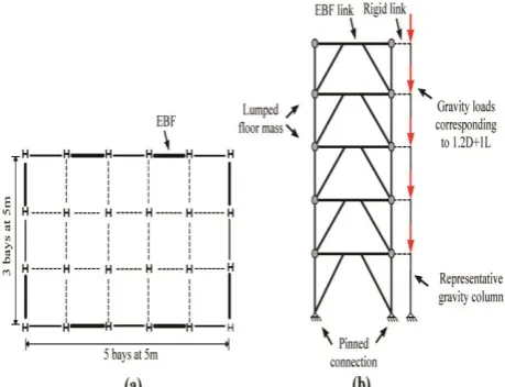
To achieve the aim of this study, twelve EBFs were designed using the DDBD procedure representing four heights (3, 5, 9 and 12-story) and three link types (short, intermediate and long). All story heights and span lengths were 3.2 and 5 m, respectively. As illustrated in Figure 3(a), lateral load resisting eccentrically braced span were considered to be placed around the perimeter of the frames. For convenience, the EBF models were assigned a specific symbol as xn
where x and n stand for the link beam behavioral type (i.e. S, I and L for short, intermediate and long links) and number of the frame stories, respectively. An area of high seismicity with soil-type II as per the Iranian Seismic Code (IS 2800) [15] is considered for the frames site conditions. The frames components designed according to the AISC 360 Specification for structural steel buildings [16] and capacity design approach. Dead and live loads were assumed as 5.0 and 2.0 kN/m2, respectively. In order to assure the intended behavior of the links, the nondimensionl link length or
length ratio ( ) of 1.2, 2.1 and 3
were assigned to the short, intermediate and long link beams, respectively. Repairable damage performance level as per Sullivan [13] was assumed for the frames and the corresponding links inelastic rotations were set to 0.08, 0.05 and 0.02 rad for short, intermediate and long links, respectively. European HE steel profiles were used for beams, columns and braces. In the stress–strain curve, a typical value for the modulus of elasticity (E=207000 MPa) is considered. Nominal yield stress (Fy) of the steel material is specified as 345
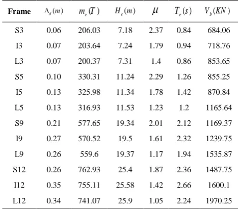
MPa. Member sizes for all frames and other related information can be found in Farahani [17]. Design results of the EBFs have been given in Table 1.
4. EBFS MACRO-MODELING TECHNIQUE
In order to investigate the nonlinear behavior of the abovementioned frames and estimate their seismic demands, individual EBFs were modeled as two-dimensional systems using the nonlinear dynamic analysis program OpenSees [14]. Important aspects of the modeling technique are as follows.
Figure 3. Plan and elevation views of EBFs
i
i
1
1
i i i hi hi
yi
p p
e M V
TABLE 1.DDBD results for the equivalent SDOF system of EBFs ( ) b V KN ( ) e T s
( ) e H m ( ) e m T ( ) d m Frame 684.06 0.84 2.37 7.18 206.03 0.06 S3 718.76 0.94 1.79 7.24 203.64 0.07 I3 853.65 0.86 1.4 7.31 200.37 0.07 L3 855.25 1.26 2.29 11.24 330.31 0.10 S5 870.84 1.42 1.78 11.34 325.98 0.13 I5 1165.64 1.2 1.23 11.53 316.93 0.13 L5 1169.37 2.12 2.01 19.34 577.65 0.21 S9 1239.75 2.32 1.61 19.5 570.52 0.27 I9 1535.87 1.94 1.17 19.37 559.6 0.26 L9 1487.75 2.36 1.87 25.4 762.93 0.26 S12 1600.1 2.66 1.42 25.58 755.11 0.35 I12 1970.25 2.24 1.05 25.9 741.07 0.34 L124. 1. Equivalent Gravity Column Since the perimeter EBFs are modeled as 2D individual frames, it is necessary to simulate properly the gravity loads and second-order (P-delta) effects. To this end, these effects were included in the 2D frames employing an equivalent gravity column (or P-delta column) pinned at the base and connected to the frame by rigid links as shown in Figure 3(b). This modeling technique has been used in the literature (Uriz and Mahin [18]) for dynamic analysis of 2D frames. In this way, the sum of the eliminated gravity columns stiffness in the 2D simulation must be considered for the P-delta column. Also, it should be mentioned that the load combination of 1.2D+L is to be taken into account to assign the P-delta column factored gravity loads during the analysis.
4. 2. Force-Controlled Members Modeling The beam, column and brace members were modeled with nonlinear force-based fiber-section beam-column elements (i.e. distributed-plasticity based elements) with 5 integration points along their length and subdivided across their section into 150 fiber elements. For members steel material, a Menegotto–Pinto uniaxial steel material model known as uniaxial Material Steel02 in OpenSees [14] was assumed. Although, bracing members in EBFs are expected to be elastic during earthquake excitation (i.e. as force-controlled members), however, in order to simulate geometric imperfections and accurate modeling of the probable in-plane and out-of-plane global brace buckling, a physical-theory model (PTM) is utilized. In the PTM, an out-of-plane camber (geometric imperfection) is applied to the longitudinal profile of
the brace members as per Uriz and Mahin [18]. To investigate the impact of the imperfection amount in PTM of bracing elements in CBFs, D’Aniello et al. [19] conducted a comprehensive numerical study. They found that, the camber magnitude affects the drift demand and the collapse mechanism and has a noticeably impact on the seismic response parameters of CBFs at collapse. In this study, however, the initial geometric imperfection (displacement) of the brace interior nodes was considered equal to 0.1% of brace unbraced length as suggested by Uriz and Mahin [18]. The beam-column connections were modeled as pinned connections.
4. 3. Deformation-Controlled Members (Link Beams) Modeling and Validation The most important part of an EBF modeling pertains to its link beams which are expected to behave as deformation-controlled elements. Link beams depending on their length ratio present different failure modes and behavior. Short links fail in shear failure mode exhibiting large plastic chord rotation angle, while long links behave in flexural failure mode with small plastic chord rotation angle. Intermediate links may exhibit a mixed shear-flexural behavior. To simulate the behavior of short and intermediate links with shear or
mixed shear-flexural failure modes, the
abovementioned fiber-based beam-column elements are useless. Although, there are some mixed shear-flexure link elements (e.g. mixed element proposed by Erfani and Kazemi [20]) in the literature, however, the link beam macro-model proposed by Richards and Uang [21] is adopted in this study with minor changes to simulate all failure modes of link beams in an EBF system. This model as shown in Figure 4(a), consists of a beam element with built-in flexural hinges with two zero-length translational springs on its both sides [21]. In this model, link beam shear failure mode is simulated by the translational shear springs at each end with a multilinear force-deformation relationship as shown in Figure 4(b). In this study, however, in order to capture the link flexural failure mode, an inelastic beam element with distributed plasticity was used instead of the elastic beam with plastic flexural hinges depicted in Figure 4(a).
A. MohebkhahandS. Farahani / IJE TRANSACTIONS C: Aspects Vol. 29, No. 06, (June 2016)
Figure 4. The link beam macro-model proposed by Richards and Uang [21]
TABLE 2. Comparison of experimental and finite element analysis maximum shear capacities
Specimen UTA 4A UTA 9 UTA 3
Section W10X33 W16X36 W10X19
Link type Shear Shear-flexural Flexural
Link length e(in) 23 48 48
( p/ P)
e M V 1.1 2 3.8
( )( )
u
V EXP kips 131 173 62
u
V (FEM )(kips) 120 192.7 63.6
Difference (%) 8.4 11.4 2.6
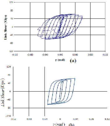
It can be seen that, the agreement between the experimental and numerical results is satisfactory with a maximum error of 11.4% for specimen UTA 9. Figures 5 compares the hysteresis curves of the experimental specimen and the corresponding model for specimen UTA 3.
5. EFFECT OF SOIL-STRUCTURE INTERACTION
In the conventional DDBD, generally assuming the rigidity of the foundation, the base shear is evaluated and distributed along the frame height. However, it has been shown by Priestley et al. [5] that the effect of Soil-Structure Interaction (SSI) in the DDBD method increases the period and damping of the structures to be designed. In this regard, Montoy and Petrini [23] investigated the effects of foundation exibility on the DDBD of RC bridges. Sullivan et al. [24] studied the effects of Soil-Structure Interaction in the DDB design of RC shear walls.
Figure 5. Hysteresis curves for specimen UTA 3: (a) test [22], (b) FEM analysis
Singh and Vinayak[25] studied the effect of SSI on the seismic behavior of both displacement-based and force-based RC bridges. In this section, the effect of SSI and foundation exibility is investigated for the designed EBFs as follows.
Lateral displacement of the structure center of mass considering the flexibility of foundation is determined using Equation (16) in which is the rotational stiffness of the foundation according to Equation (17) [5]. In these equations, and BF are foundation
translational stiffness and width and LF and hF are
length and depth of the foundation, respectively. Also, overturning moment M is calculated using Equation (18).
( )( )
j M K hF He
(16)
3
12
F F
v
B L
K K (17)
( )
b F e
M V h H (18)
Then, the base rotation due to the flexibility of foundation is evaluated using Equation (19) and therfore the ultimate drift and the total story drift capacity of the structural elements are modified. dF in
Equation (20) is the modified dispalcement and Equation (21) is the modified total story drift capacity of the EBFs, respectively, considering the foundation flexibility.
(19)
K
v K
(H h )
b e F
F V
K
(20)
(21)
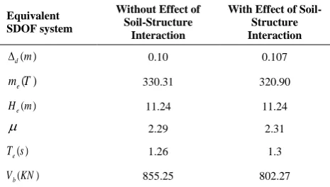
As it was stated previously, considering SSI may increase the structure period reducing the amount of base shear forec. To investigate the sensitivity of DDB designed EBFs to the effect of foundation flexibility, the 5-story EBF with short link (S5) is redesigned here considering the effect of foundation flexibility. The assumed dimensions and rotational stiffness of the foundation is given in Table 3. The DDBD results of the equivalent SDOF system indicates that considering SSI reduces the base shear force up to 6% for the studied frame. Accordingly, as can be observed in Tables 5 and 6, the componets size is reduced to some extent.
TABLE 3.Dimensions of Foundation
K(Kn.m/ rad)
F h
(m)
F L
( )m
F
B
(m)
Dimensions of Foundation
5 180 10
1 5
4
TABLE 4.DDBD results for the equivalent SDOF system of S5
With Effect of Soil-Structure Interaction Without Effect of
Soil-Structure Interaction Equivalent SDOF system 0.107 0.10 ( ) d m 320.90 330.31 ( ) e m T 11.24 11.24 ( ) e H m 2.31 2.29 1.3 1.26 ( ) e T s 802.27 855.25 ( ) b V KN
TABLE 5.Design results for S5 without the effect of SSI
Level Brace
Section Column Section Link Section Link Length (m)
1 HE 160 B HE 240 B HE 260 B 0.68
2 HE 160 B HE 200 B HE 260 B 0.68
3 HE 140 B HE 140 B HE 240 B 0.63
4 HE 120 B HE 100 B HE 200 B 0.51
5 HE 120 B HE 100 B HE 160 B 0.40
TABLE 6. Design results for S5 considering the effect of SSI
Level Brace
Section Column Section Link Section Link Length (m)
1 HE 140 B HE 220 B HE 220 B 0.59
2 HE 140 B HE 180 B HE 220 B 0.59
3 HE 140 B HE 140 B HE 220 B 0.59
4 HE 120 B HE 100 B HE 180 B 0.47
5 HE 120 B HE 100 A HE 160 B 0.40
TABLE 7. Earthquake records used for the EBFs Scale factor PGA
Earthquake name
No.
12-story 9-story 5-story 3-story 0.889 0.743 0.573 0.558 0.385 Cape Mendocino R1 1.094 0.914 0.706 0.687 0.474 Chi-Chi, Taiwan R2 0.344 0.287 0.222 0.216 0.149 Kocaeli, Turkey R3 0.653 0.546 0.610 0.410 0.283 Landers R4 0.554 0.463 0.357 0.348 0.240 Loma Prieta R5 0.642 0.536 0.414 0.403 0.278 Northridge R6 0.653 0.546 0.421 0.410 0.283 San Fernando R7
6. ANALYSIS RESULTS AND DISCUSSION
6. 1. Earthquake Records Selection And Scaling
To perform nonlinear dynamic analyses on the EBFs models, a suite of 7 earthquake records compatible with the site conditions (soil-type II) and the Iranian Seismic Code (Standard 2800) [15] requirements selected from PEER NGA Database [26]. The earthquake records were scaled in such a way that the average value of the 5 percent damped response spectra for the suite of motions was larger than the design response spectrum for the periods between 0.2T to 1.5T. T is the fundamental period of the frame as per Standard 2800 [15]. The selected 7 earthquake records and the corresponding scale factors for the EBFs have been shown in Table 7. As can be seen in Figure 6, the average response spectrum of the selected records is higher than the design spectrum between the code specified ranges of period (shown with vertical dash-dot lines in the figure).
6. 2. Nonlinear Dynamic Analysis In this section, all of the EBFs are subjected to nonlinear dynamic analysis using the scaled earthquake records presented in the previous section.
dF d j
, , , ,
, 1 ,link,i
2 2
sin 2
2 .
(H h )
br i y v i
i y
b i br i cols i y i s i p
b b
b e F
K
L e
K h h e
A. MohebkhahandS. Farahani / IJE TRANSACTIONS C: Aspects Vol. 29, No. 06, (June 2016)
Figure 6. Response spectra of the scaled records and the design spectrum for 3-story EBFs.
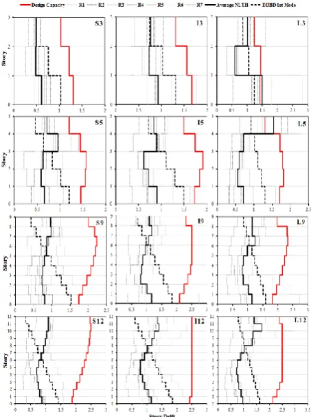
In order to apply damping to the physical frame models, a tangent stiffness-proportional Rayleigh damping with 5% viscous damping was utilized as suggested by Sullivan [13]. Nonlinear dynamic analysis outputs for each frame as shown in Figure 7 include: the DDBD story drift capacity, dynamic inter-story drifts for each record and their average. This figure shows that, for all of the EBFs (except for models L5 and L3), the average story drift demands are less than the design story drift capacities. Although the average story drifts demand of model L5 in its top story has been exceeded the design story drift capacity, however from a practical point of view, this higher drift demand may be of limited importance. This is because, in practice instead of discrete profile selection for each story column, the top story profile generally matches the size of its below story column. This higher drift demand may be attributed to the effects of higher modes. As mentioned in Sec. 2, the effect of higher modes in the proposed DDBD for EBFs is taken into account using the higher mode reduction factor ( ) which is applied to the design displacement profile of frames taller than 6-story. Thus, it appears that the effect of higher modes in EBFs depends not only on the number of stories but also on their link beams length ratio. Because, increasing the link length reduces the EBFs lateral stiffness and hence the fundamental period of the frame increases. To reach a confident decision on the EBFs height limit to apply the higher modes effect, a separate comprehensive study should be conducted. However, it seems that the higher mode reduction factor should be applied for the 5-story EBF with long link studied here, too. Although the average story drifts demand of model L3 in its first story has been exceeded the design story drift capacity, however this increase is not so significant and can be ignored.
Figure 7. Comparison of the design inter-story drift distributions with the results of dynamic analyses
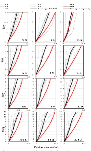
These results indicate that the proposed DDBD procedure by Sullivan [13] is generally successful in limiting the peak story drift demands of EBFs with different link length ratios to the design drift capacities. Variations of the design lateral displacement profile together with results of dynamic analyses have been illustrated in Figure 8. This figure indicates that the DDBD lateral displacement profile generally overestimates the frames real profile. This is another issue pertaining to the DDBD of EBFs which should be studied separately in future work. Figure 9 shows the EBFs plastic link rotations demands. As can be seen, the plastic link rotation demands for the EBFs (except for models L3 and L5) are below the design link rotation capacities indicating the adequacy of the DDBD in limiting the links rotation demands. For the higher link rotation demand of model L5, the abovementioned discussion can also be valid. This figure also indicates simultaneous yielding of all links along the frames height which leads to the occurrence of intended ductile failure mechanism.
Figure 8. Comparison of the design lateral displacement profiles with the results of dynamic analyses
Figure 9. Comparison of the design plastic link rotation capacities with the results of dynamic analyses
7. CONCLUSIONS
In this paper, a two-dimensional finite element macro-model developed for the nonlinear static and dynamic analysis of twelve EBFs designed using the DDBD method. The results of dynamic analyses showed that for all of the EBFs, the average story drift demands are generally less than the design story drift capacities. This result indicates that the proposed DDBD procedure by Sullivan is generally successful in limiting the peak story drift demands of EBFs with different link length ratios to the design drift capacities. However, it appears that the effect of higher modes in
EBFs depends not only on the number of stories (as implemented in the DDBD procedure) but also on their link beams length ratio. In other words, the higher modes modification factor has not been validated for EBFs with long links and therefore requires further investigation. Moreover, it was found that the proposed DDBD lateral displacement profile overestimates the EBFs real profile. Also, it was shown that by considering the effects of Soil-Structure Interaction in DBD design of EBFs, the base shear force reduces which may lead to an economical design of EBFs. The distribution of the inelastic link rotations demands along the frames height showed that the DDB designed EBFs are generally capable of attaining their intended ductile failure mechanism.
7. REFERENCES
1. Popov, E.P., "Recent research on eccentrically braced frames",
Engineering Structures, Vol. 5, No. 1, (1983), 3-9.
2. AISC 341-10. Seismic Provisions for Structural Steel
Buildings. Chicago (IL): American Institute of Steel Construction, (2010).
3. Richards, P.W. and Thompson, B., "Estimating inelastic drifts and link rotation demands in EBFs", Engineering Journal-American Institute Of Steel Construction Inc, Vol. 46, No. 3, (2009), 123-135.
4. Koboevic, S. and David, S.O., "Design and seismic behaviour of taller eccentrically braced frames", Canadian Journal of Civil Engineering, Vol. 37, No. 2, (2010), 195-208.
5. Priestley MJN, Calvi, GM and Kowalsky, MJ, “Displacement
Based Seismic Design of Structures”, IUSS Press, (2007). 6. Kermani, H., Behnamfar, F. and Morsali, V., "Seismic design
of steel structures based on ductility and incremental nonlinear dynamic analysis", International Journal of Engineering-Transactions A: Basics, Vol. 29, No. 1, (2015), 23-30.
7. Sullivan, T.J., "An energy-factor method for the
displacement-based seismic design of RC wall structures", Journal of Earthquake Engineering, Vol. 15, No. 7, (2011), 1083-1116.
8. Izadi Z. E. and Moghadam, A., "Two important issues relevant
to torsional response of asymmetric 8-story RC
buildingdesigned with direct displacement based design
approach", International Journal of
Engineering-Transactions C: Aspects, Vol. 28, No. 9, (2015), 1257-1267.
9. Macedo, L. and Castro, J., "Direct displacement-based seismic
design of steel moment frames", in Proceedings of 15th World Conference on Earthquake Engineering, Lisbon, Portugal., (2012).
10. Lopez, R.G , “Development of a displacement-based design method for steel frame-RC wall buildings”, ROSE School MSc thesis in earthquake engineering, IUSS Pavia, Italy, (2007).
11. Della Corte, G. and Mazzolani, F., "Theoretical developments and numerical verification of a displacement-based design procedure for steel braced structures", in Proceedings of the 14th world conference on earthquake engineering, Beijing., (2008), 12-17.
A. MohebkhahandS. Farahani / IJE TRANSACTIONS C: Aspects Vol. 29, No. 06, (June 2016)
13. Sullivan, T.J., "Direct displacement-based seismic design of steel eccentrically braced frame structures", Bulletin of Earthquake Engineering, Vol. 11, No. 6, (2013), 2197-2231. 14. PEER. “Open system for earthquake engineering simulation
(OpenSees)”, Version 2.4.0. Berkeley: Pacific Earthquake Eng. Research Center, Univ. of California; (2005).
15. IS 2800, “Iranian code of practice for seismic resistant design of buildings” Building and Housing Research Center, Tehran, Iran, (2014).
16. AISC 360-10, “Specification for structural steel buildings” Chicago, IL: American Institute of Steel Construction, (2010). 17. Farahani S., "Evaluation of the direct displacement-based
seismic design method for steel eccentrically braced frames", Malayer University, Iran, Master’s thesis, (2015).
18. Uriz, P. and Mahin S., "Towards earthquake resistant design of concentrically braced steel structures", PEER Report 2008/08, University of California, Berkeley, California, (2008). 19. D'Aniello, M., La Manna Ambrosino, G., Portioli, F. and
Landolfo, R., "The influence of out‐of‐straightness imperfection in physical theory models of bracing members on seismic performance assessment of concentric braced structures", The Structural Design of Tall and Special Buildings, Vol. 24, No. 3, (2015), 176-197.
20. Erfani, S. and Kazemi, M. T., "Shear-flexural interaction in
analysis of reduced web section beams using VM link
element", International Journal Of Engineering
Transactions B Applications, Vol. 20, No. 1, (2007), 23-35. 21. Richards, P.W. and Uang, C.-M., "Testing protocol for short
links in eccentrically braced frames", Journal of Structural Engineering, Vol. 132, No. 8, (2006), 1183-1191.
22. Arce, G., "Impact of higher strength steels on local buckling and overstrength of links in eccentrically braced frames", Masters Thesis, University of Texas, Austin, Tex., USA, (2002).
23. Montoy, R.A.Z. and Petrini, L., "Direct displacement based design on bridges with foundation exibility", Institute for Advanced Study of Pavia (IUSS) Master’s thesis, (2008) 24. Sullivan, T., Salawdeh, S., Pecker, A., Corigliano, M. and
Calvi, G., "Soil-foundation-structure interaction considerations for performance-based design of RC wall structures on shallow foundations", Soil-Foundation-Structure Interaction, (2010), 193-200.
25. Singh, R. and Vinayak, H.K., "Assessment of soil-structure interaction in seismic bridge pier analysis using force and displacement based approaches", Selected Scientific Papers-Journal of Civil Engineering, Vol. 10, No. 2, (2015), 113-126 26. PEER, NGA Database, Pacific Earthquake Engineering
Research Center, http://peer.berkeley.edu /nga/, (2013).
Seismic Behavior of Direct Displacement-based Designed Eccentrically Braced
Frames
A. Mohebkhah, S. Farahani
Department of Civil Engineering Faculty of Civil and Architectural Engineering, Malayer University, Malayer, Iran
P A P E R I N F O
Paper history:
Received 20 November 2015 Received in revised form 28 May 2016 Accepted 02 June 2016
Keywords:
Direct Displacement-based Design Nonlinear Dynamic Analysis Pushover Analysis
Steel Eccentrically Braced Frame Seismic Behavior
ديكچ ه
شٍر سا یکی باق یحازط یازب زیخا ِّد ٍد رد ِک دزکلوػ یاٌبه زب یحازط یاّ
لپ ٍ یضزب یاّراَید،حلسه يتب یاّ اّ
یه ىاکهزییغت یاٌبه زب نیقتسه یحازط شٍر ،تسا ِتفای ِؼسَت ُسزل ىاکهزییغت سایً يیوخت یازب ،شٍر يیا رد .ذضاب
یا
یه ُدافتسا لداؼه یداسآ ِجرد کی يیشگیاج ُساس کی سا ،یداسآ ِجرد ذٌچ نتسیس کی یلػ .دَض
ِک یدایس تاؼلاطه نغر
ُساس عاًَا یحازط یازب شٍر يیا سا ُدافتسا ٌِیهس رد باق یحازط یازب ،ُذض ماجًا اّ
زیت اب ازگاٍ یذٌبراْه اب یدلاَف یاّ
افزص ُاتَک ذًَیپ "
رد غهاج شٍر کی یحازط شٍر ییآراک ىاشیه ،قیقحت يیا رد .تسا ُذض داٌْطیپ ِتضذگ یٌف تایبدا
باق یحازط یازب ىاکهزییغت یاٌبه زب نیقتسه یه رازق یسرزب درَه ذٌلب ٍ طسَته ،ُاتَک ذًَیپ زیت عاًَا اب ازگاٍ یاّ
.دزیگ
داذؼت اذتبا ،اتسار يیا رد 21
داذؼت اب ازگاٍ ُذض یذٌبراْه باق ًَِوً قبط
تا 3 ، 5 ، 9 ٍ 21 یاّزیت دزکلوػ عاًَا اب ِقبط
ِیبض یازب .ذیدزگ یحازط زظً درَه یداٌْطیپ شٍر اب ذًَیپ ِخزچ راتفر یساس
یداٌْطیپ یٍزکاه لذه ،ذًَیپ یاّزیت یا
.تفزگ رازق یجٌسرابتػا درَه دَجَه تاطیاهسآ جیاتً اب ٍ ُذض سابتقا یٌف تایبدا رد صه یطخزیغ راتفر فیصَت یازب
حلا
ىاولا زب یٌتبه ُدزتسگ یزیوخ لذه سا یدلاَف باق یاضػا یه ُدافتسا یزبیف یاّ
لذه کیٌکت یجٌسرابتػا سا ذؼب .دَض
-ُسزل راتفر ،ذًَیپ یاّزیت یٍزکاه یساس باق یا
یًاهس ِچخیرات یکیهاٌید لیلحت شٍر سا ُدافتسا اب یذؼبٍد یازگاٍ یا
ِػَوجه تحت یطخزیغ ِلشلس یاّدرَکر سا یا
مزً سا ُدافتسا اب یباختًا یاّ راشفا
OpenSees
صیازیٍ( 1.4.2 درَه )
تفزگ رازق یبایسرا ٍ یسرزب یه ىاطً جیاتً .
باق ِک ذّد یه ،قیقحت يیا رد ىاکهزییغت یاٌبه زب ُذض یحازط یاّ
ِب ذًٌاَت
.ذٌسزب دَخ راظتًا درَه دزکلوػ حطس
![Figure 1. Conceptual framework of DDBD method [5].](https://thumb-us.123doks.com/thumbv2/123dok_us/216712.2016144/2.595.322.532.99.271/figure-conceptual-framework-ddbd-method.webp)
![Figure 2. Elastic deformation components of an EBF [13].](https://thumb-us.123doks.com/thumbv2/123dok_us/216712.2016144/3.595.62.277.574.712/figure-elastic-deformation-components-ebf.webp)