A Novel Method for Commutation Torque Ripple Reduction of
Four-Switch, Three-Phase Brushless DC Motor Drive
A. Halvaei-Niasar
*, A. Vahedi
**and H. Moghbelli
***Abstract: This paper presents an original study on the generated torque ripples of phase commutation in the Four-Switch, Three-Phase Inverter (FSTPI) Brushless DC (BLDC) motor drive which is suitable for low cost applications. Analytic values of torque ripple and commutation duration are obtained for different operation conditions. Moreover, limitation on the speed range operation caused from splitting of the DC-link voltage is shown exactly. Then a novel current control technique is developed to minimize the commutation torque ripple for a wide speed range. The technique proposed here is based on a strategy that the current slopes of the rising and the decaying phases during the commutation intervals can be equalized by proper duty-ratios at commutations. Finally, the validity of the proposed analysis and developed torque ripple reduction technique are verified via simulation. Keywords: Brushless DC Motor, Commutation Torque Ripple, Four-Switch Inverter.
1 Introduction1
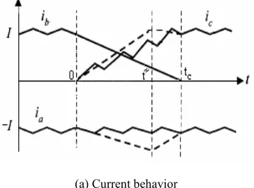
Brushless DC motors with trapezoidal back-EMF have been widely used due to their high efficiency, high torque density, low maintenance and ease of control [1]. BLDC motors are fed with rectangular stator current as shown in Fig. 1 and therefore, the developed torque is theoretically constant. However, in practice torque ripple exists due to the stator inductance, cogging effect and motor feeding [2, 3]. Carlson announced relation between the commutation torque ripple and the speed of a six-switch inverter BLDC motor drive [4]. For low cost application, the four-switch, three-phase inverter (FSTPI) employs only four switches, a pair of complementary switches as shown in Fig. 2. A comparison between six and four switch inverters for a three-phase BLDC motor drive have been presented in [5, 6]. Although in the four-switch inverter, generating of 120o conducting current profiles is inherently difficult. Therefore, in order to use the four-switch topology for three-phase BLDC motor, new control
Iranian Journal of Electrical & Electronic Engineering, 2007. * The Author is with the Department of Engineering, University of Kashan, Kashan, Iran. He is currently a Ph.D. student at Department of Electrical Engineering, Iran University of Science and Technology, Tehran, Iran.
E-mail: [email protected].
** The Author is an Associate Professor and member of Center of Excellence for Power System Automation and Operation at the Iran University of Science and Technology.
E-mail: [email protected].
*** The Author is with the Department of ECE, Isfahan University of Technology, Isfahan, Iran. He is currently a visiting Assistant Professor at the Department of Science & Mathematics, Texas A&M University at Qatar, Doha, Qatar.
E-mail: [email protected].
methods should be used. The reported methods due to asymmetrical voltage problem have paid to conduction interval operation and so there aren't any considerable works for commutation intervals.
In this paper, an original study of commutation for FSTPI topology is proposed and its drawbacks are explored analytically. Then, the possibility of reducing the torque ripple due to commutation for a FSTPI brushless dc motor drive is proposed. Finally, a novel torque ripple reduction method is developed to enhance the drive performance it is demonstrated via simulation. 2 Analysis of BLDC Motor Drive Using FSTPI
2.1 Modeling of FSTPI-BLDC Motor Drive
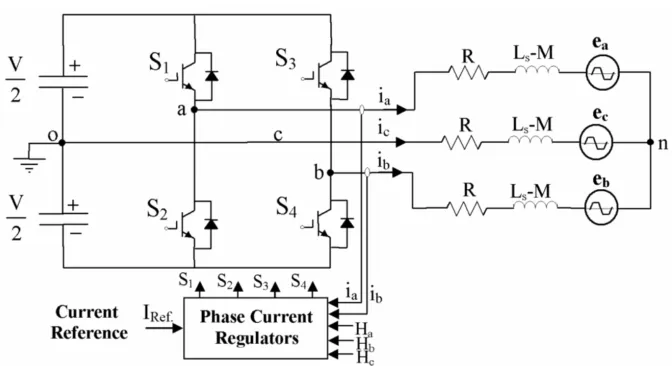
The overall block diagram of a FSTPI-BLDC motor drive is shown in Fig. 2. Motor is connected to a, b legs of inverter and mid point of DC-Bus. Mathematical model of a three-phase BLDC motor is expressed as:
an a s a a
bn b s b b
cn c s c c
v R 0 0 i L M 0 0 i e
d
v 0 R 0 i 0 L M 0 i e
dt 0 0 R
v i 0 0 L M i e
−
= × + − +
−
(1)
and,
a an no
b bn no
c cn no
v v v
v v v
v v v
= +
= +
= +
(2)
where, vxo, vno, vxn, ix, and exn, are the line terminal voltage and motor star point with respect to point o, phase terminal voltage, phase current, phase back-EMF
voltage, and R, Ls and M are the phase resistance, phase inductance and mutual inductance respectively [7]. Generally a BLDC motor has two operation region; conduction region and commutation region. In the conduction region, two phases always conduct the current. Commutation region is transient region between two conduction modes and therefore, three phases including rising, decaying, and non-commutating phases are all conducting.
2.2 Current Regulation
In a Four-switch BLDC motor drive, current regulation needs more attention rather than six-switch drive. According to Fig. 1, in mode II and V, phases a and b are conducting the current and phase c is silent. However, the back EMF voltage of phase c (ec) can cause additional and unexpected current, resulting in
current distortion in the phases a, b. Therefore, if ia and ib are controlled independently, influence of the voltage ec can be blocked and therefore, there isn’t any current distortion in phase a and b. Fig. 2 shows the configuration of a FSTPI-BLDC motor drive with employing the direct phase current (DPC) control technique that two current sensors are used. In addition to conduction regions, it is possible to extend the DPC control technique to commutation regions. For low speed conditions, this technique can regulate the currents well. Therefore, the current and torque don't contain any ripple more than hysteresis band. However, it has been shown that DPC control technique can not reduce commutation torque ripple at high speed conditions [8]. Therefore, the effective control technique should be developed.
Fig. 1 Ideal signal waveforms of three-phase BLDC motor.
Fig. 2 Configuration of FSTPI-BLDC motor drive system via direct phase current control method.
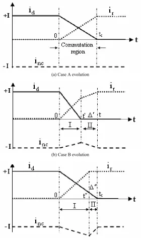
3 Analysis of Commutation in FSTPI-BLDC Motor 3.1 Phase Current Behaviors in Commutations Phase commutations in all modes of a six-switch inverter BLDC motor drive are the same together whereas, in four-switch inverter, they are different. Depend on the motor speed, three different cases may be found for each mode as the following:
Case A: Decaying current (id) vanishes at the same time that the rising current (ir) reaches to its final value (+I) as shown in Fig. 3(a).
Case B: Decaying current vanishes before that the rising current reaches to its final value as shown in Fig. 3(b).
Case C: Rising current reaches to (+I) before that the decaying current vanishes as shown in Fig. 3(c).
For the following analysis, the stator resistance is ignored and the phase back-EMF voltages is supposed to remain constant during commutation. These assumptions lead to analytic equations for developed torque ripple values, commutation durations and etc.
(a) Case A evolution
(b) Case B evolution
(c) Case C evolution
Fig. 3 Current behaviors during commutation.
3.2 Current Commutation
In this section, the current commutations are analyzed at positive current level which are corresponding to three modes II, IV and VI. Commutation at negative level in modes I, III and V can be explained in the same manner.
• Mode II
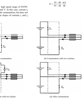
In mode II, id, ir and inc (non-commutated current) are corresponding to ic, ia and ib respectively and commutation is from phase c to phase a as shown in Fig. 1. The current is transferred by switching on S1 and S4. Nevertheless, the current is not transferred directly and it is done firstly by action of the freewheeling diodes. The circuit before commutation is shown in Fig. 4(a). Immediately after switching on S1, the circuit topology is shown in Fig. 4(b). From this point, three cases A, B or C may be found. To analyze of circuit in these cases, the current derivatives are firstly obtained as follow. For sequence of Fig. 4(b), the KVL equations using Eq. (1) are written as:
a
a a no
b
b b no
c
c c no
di V
R i L e V
2 dt
di V
R i L e V
2 dt
di
0 R i L e V
dt + = ⋅ + + + − = ⋅ + + + = ⋅ + + + (3)
where,L=Ls−M. Substituting the phase back-EMF voltages with their magnitude, results:
a b c
no
e e e E
V
3 3
+ +
= − = − (4)
With simplifications, current derivatives are expressed as:
a
b
c
di 3V 4E
dt 6L
di 3V 8E
dt 6L di 4E dt 6L − = − = − = − (5)
With the same manner, for sequence of Fig. 4(c), current derivatives are obtained from:
a
b
c
di 3V 4E
dt 6L
di 3V 8E
dt 6L di 4E dt 6L + = − + = = − (6)
According to the motor speed, three following cases can be occurred:
Case A:
In this case, ic and ia reach to their final values simultaneously and therefore, their slopes are equal. The condition for occurring case A from Eq. (5) is given by:
E 3
V=8 (7)
Taking the beginning of the commutation as the time origin and using Eq. (5), ia is obtained from:
a
3V 4E
i (t) t
6L −
= (8)
Therefore, the commutation time tc can be calculated from: c 3LI t 2E = (9) Case B:
In this case, the commutation is done in two sequences I and II. In the first sequence(0<t<t′), ic vanishes at
t
t= ′. It is characterized by the circuit of Fig. 4(b) and from Eq. (5), ic(t) is obtained from:
c
4E
i (t) I t
6L
= − (10)
The duration of this step is obtained from Eq. (10) as:
6LI t
4E
′ = (11)
At the end of this sequence, from Eq. (6) ia is given by:
a
3V 4E
i (t ) I
4E −
′ = (12)
For second sequence(t′ < <t t )c , two phases a and b are conducting in series(ia = −i )b , and KVL is as:
a b a
a b
di di di
V L e L e 2L 2E
dt dt dt
= + − − = + (13)
Therefore, the current ia is expressed by:
a
3V 4E V 2E
i (t) I t
4E 2L
− −
= + (14)
At the end of sequence II, ia reaches to +I. So, the duration of this step (∆′) is obtained from:
3V 8E 2LI
V 2E 4E
− +
′
∆ = ⋅
− (15)
The total duration of the commutation in case B is calculated from Eq. (11) and Eq. (15):
c
LI
t t
V 2E
′ ′
= + ∆ =
− (16)
The condition to have the case B can be obtained from relations ia(t′)<+I and 0<tcas:
3 E
0.5
8<V< (17)
This equation explores the high speed range of FSTPI-BLDC motor in modes II and V. In this case, current ib is not directly involved in the commutation, but does not remain constant because the slopes of currents ic and ia
are different. The point E / V=0.5 is the limit point for controlling the current and at higher speeds, the current control is impossible.
Case C:
For this case, the commutation is also made in two sequence I and II as shown in Fig. 3(c). At the first sequence(0< <t t )′′ , current ic vanishes and it is characterized by the circuit of Fig. 4(b). At the end of this sequence, ia(t) reaches to +I. Using ia(t) from Eq. (5), duration of sequence I is obtained from:
6LI t
3V 4E ′′ =
− (18)
Second sequence(t′′ < <t t )c corresponds to Fig. 4(c) and at the end of sequence II, ic reaches to zero. Therefore, the duration of this step (∆′′) is:
3V 8E 6LI 3V 4E 4E
− ′′
∆ = ⋅
− (19)
(a) Before commutation (b) Commutation with two switches
(c) Commutation with two diodes (d) After commutation
Fig. 4 Commutation sequence in mode II.
The total duration of the commutation in case C is the summation of Eq. (18) and Eq. (19) and is obtained from:
c
3LI
t t
2E ′′ ′′
= + ∆ = (20)
The condition to have the case C is given by ic(t′′)>0, that results:
E 3
V<8 (21)
This equation explores the low speed range of FSTPI-BLDC motor in modes II and V. In this case, current ib does not remain constant because the derivatives of currents ic and ia are different. Hence, in low speed range non-commutated current ib has some swell as shown in Fig. 3(c) and therefore, the torque increases.
• Mode IV
In this operation mode, id, ir and inc are corresponding to ia, ib and ic respectively as shown in Fig. 1. According to the slopes of the currents ia and ib, it can be proved that in this mode always ib < ia is valid and therefore, only case B occurs. The current derivatives are obtained from:
a
b
di 3V 4E
dt 6L
di 3V 4E
dt 6L
+
= −
− +
= −
(22)
With the same manner of case B in mode II, the following equations are derived:
6LI t
3V 4E ′ =
+ (23)
8E 4LI
3V 4E V 4E ′
∆ = ⋅
+ − (24)
c
2LI t t
V 4E
′ ′
= + ∆ =
− (25)
The condition to have this case is expressed as:
E 0.25
V< (26)
• Mode VI
In this operation mode, id, ir and inc are corresponding to ib, ic and ia respectively. Commutation is from phase b to phase c and the current is transferred by switching off S3 and the switch S2 is held on. With the same manner as mode II, three following cases can occur:
Case A:
c 6LI t
3V 4E
=
− (27)
The condition for this case is:
E 1
V=8 (28)
Case B:
c
2LI t t
V 4E
′ ′
= + ∆ =
− (29)
The condition for case B that results from i (t )c ′ < +I and 0<tc is obtained from:
1 E
0.25
8< V< (30)
Similar to the modes II and IV, point E / V=0.25 is the limit point for controlling the current at mode VI and at higher speed, the current control is impossible.
Case C:
c
6LI 4V 4E
t t
2V 4E 3V 4E
− ′′ ′′
= + ∆ = ⋅
− + (31)
The condition to have the case C is:
E 1
V<8 (32)
In this section, the phase commutation in modes II, IV and VI have been analyzed. Developed equations show that the current commutations of six modes are different together and also are different to the commutation of six-switch inverter BLDC motor drive [4].
4. Torque Ripple at Commutations
General expression of torque for each operation mode is given by:
n 2EI
T= =T
ω (33)
Also, the torque between commutations is given by:
d d r r nc nc 1
T= (e i +e i +e i )
ω (34)
Supposing the back-EMF voltages are constant in the commutation result in:
nc
d r nc
2E i 1
T= (E i⋅ + ⋅ − ⋅E i E i )= − ⋅
ω ω (35)
To calculate the torque ripple during commutation, the current value of the non-commutated phase should be obtained at the end of the corresponding case.
• Mode II
According to Fig. 4(b) and using Eq. (5) the current of the non-commutated phase is expressed as:
nc b
3V 8E
i (t) i (t) I t
6L −
= = − − (36)
Case A:
In this case, ib(t) is constant in commutation and then, torque remains constant and is equal to Tn. Therefore,
T 0 (pu)
∆ = (37)
Case B:
By substituting t′ from Eq. (11) into Eq. (34), the torque at the end of the first step is obtained from:
2EI 3V 8E
T(t ) 1
4E
−
′ = +
ω (38)
With some calculations and dividing by Tn, the relative torque ripple in per unit is given by:
n
n
T(t ) T 3V 8E
T (pu)
T 4E
′ − −
∆ = = (39)
Case C:
By substituting t′′ from Eq. (18) into Eq. (34), the torque at the end of the first step is obtained from:
2EI 3V 8E
T(t ) 1
3V 4E
−
′′ = +
ω − (40)
Therefore, the relative torque ripple is given by: n
n
T(t ) T 3V 8E
T (pu)
T 3V 4E
′′ − −
∆ = =
− (41)
With the same manner for mode IV and mode VI, the results are as the following:
•Mode IV
n
n
T(t ) T 8E
T (pu)
T 3V 4E
′ − −
∆ = =
+ (42)
•Mode VI Case A:
T 0 (pu)
∆ = (43)
Case B:
n
n
T(t ) T V 8E
T (pu)
T V 4E
′ − − ∆ = = + (44) Case C: n n
T(t ) T V 8E
T (pu)
T 2V 4E
′′ − −
∆ = =
− (45)
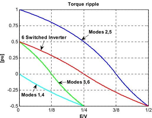
The same explanations can be presented for modes I, III and V that the same results for commutation torque ripple are obtained. Equations (37), (39) and (41)-(45) are only valid if the current can be controlled. It means they must not exceed their corresponding limit points. For a typical BLDC motor, the commutation duration and the relative torque ripple calculated as equations (36)-(45) are shown in Fig. 5 and Fig. 6 respectively. For six-switch inverter topology, commutation duration has an optimum value at point V=4E and also the current limit point is V=2E. However, in the four switch topology, commutation duration for all modes is increasing when the speed increases and has not any optimum value. Moreover, the current limit point reduces to point V=4E. This is the main drawback of four-switch topology. It means that for E / V 1/ 4> region, the current control is impossible and actually the
drive operation range is limited to E / V 1/ 4< conditions and half of the nominal speed range of BLDC motor drive is accessible.
On the other hand, the torque ripple equations show that for a constant voltage of DC-Bus, the relative torque ripple due to commutation is independent of the current, but it depends on the back-EMF voltage (i.e. speed). Because of asymmetrical stator phase voltages, the torque ripple are different at each operation mode as shown in Fig. 6. The relative torque ripple reaches to 50% and 100% at low speed in different modes and it reduces to -50% at V=4E. In the next section, for commutation torque ripple reduction at E / V 1/ 4< region, a novel control technique is presented.
5 Commutation Torque Ripple Reduction
Commutation analysis of four-switch inverter shows that the commutation ripple always occur and torque ripple reduction is necessary. Using the direct phase current (DPC) control technique at commutation duration can eliminate the commutation torque ripple in low speed range (case C) in a FSTPI-BLDC motor drive. However, for high speed range (case B) it has been shown that DPC control method can not eliminate the commutation torque ripple [8]. Therefore, a novel control technique based on the current slope equalization of two commutated currents is developed. This technique eliminates the torque ripple at wide range lower than current limit point V=4E. Proposed technique is developed for modes II, IV and VI and for other modes, the developed relations are the same.
0 1/8 1/4 3/8 1/2
0 5 10 15 20x 10
-4
E/V
[s
e
c
]
Commutation duration
6 Switch Inverter
Modes 2,5 Modes 1,4
Modes 3,6
Fig. 5 Commutation duration in different modes.
0 1/8 1/4 3/8 1/2
-0.5 -0.25 0 0.25 0.5 0.75 1
E/V
[p
u
]
Torque ripple
Modes 2,5
Modes 1,4
Modes 3,6 6 Switched Inverter
Fig. 6 Relative torque ripple amplitude in different modes.
5.1 Torque Ripple Reduction in Mode II Case B:
In this case the current limit point is E / V=0.5and so for interval 3/ 8 E / V< <0.5, the current control or torque ripple reduction can be used. However the region 3/ 8 E / V< <0.5 is above of the current limit point for modes I, III, IV, VI that is V=4E. It means the current control in this case of two modes II and V is useless.
Case C:
In this case, it is clear that ic < ia , as shown in Fig. 7(a) and from Eq. (6). To match the slopes of the currents, switching on S4 decreases the slope of ia and slope equalization can be obtained. Solid line shows the modulated waveform of the current ia. Fig. 7(b) shows the circuit topology when S1 is off. KVL equations during commutation intervals can be written as:
a
a a no
b
b b no
c
c c no
di V
S R i L e V
2 dt
di V
R i L e V
2 dt
di
0 R i L e V
dt ⋅ = ⋅ + + + − = ⋅ + + + = ⋅ + + + (46)
and the voltage of the motor star point is given by:
no
V E
V (S 1)
6 3
= − ⋅ − (47)
that, S= +1 refers to S1 is on during the switching and
S= −1 refers to S1 is off. The averaged slopes of commutated currents are obtained as the following:
[
]
[
]
__ a __ c di 14D V V 4E
dt 6L
di 1
2D.V 2V 4E
dt 6L
= ⋅ − −
= − + −
(48)
Equalizing slopes of currents ia and ic leads to:
2,Low _ 1
1 4E
D
2 V
= − + (49)
From Eq. (21), 0<E / V<3 / 8. But, D2,Low will be between 0 and 1 if 1/ 8<E / V<3 / 8.Moreover, it can be shown that for interval 0<E / V<1/ 8, by switching on S4, slope matching between currents ia and ic is accessible. Therefore, in this case the duty cycle is obtained from:
2,Low _ 2
3 2E D
4 V
= + (50)
• Torque Ripple Reduction in Mode IV
Section 3.2 stated that in mode IV only case B occurs. Equation (22) shows ib < ia . Matching of these current slopes can be obtained either by decreasing the slope of ia via switching of S1. Fig. 8 shows the circuit topology and current behavior in this case. With the same manner, the averaged slopes of commutated currents are obtained:
[
]
[
]
__ a __ b di 14D.V 3V 4E
dt 6L
di 1
2D.V 3V 4E
dt 6L
= − −
= − + −
(51)
Equalizing the slopes of the currents ia and ib results:
4,High 4E D
V
= (52)
Equation (26) presents that the current control limit point in modes I and IV is E / V=0.25. Therefore, the developed duty cycle D4,High is valid.
• Torque Ripple Reduction in Mode VI
Case B:
From Eq. (30), the current control for interval 1/ 8<E / V<0.25 is possible. Fig. 9 shows the circuit topology and current behavior in this case and it can be shown that ic < ib . In order to match the current slopes, switching on S3 decreases the slope of ib. Using the same explanation, duty cycle is obtained from:
6,High
4E 1 D
V 2
= − (53)
From Eq. (30), 1/ 8<E / V<0.25 and therefore, the developed duty cycle is valid.
Case C:
In this case, it can be shown that ib < ic . To match of these current slopes, switching on S2 decreases the slope of ic and therefore, the slopes become equal. Fig. 10 shows the circuit topology and current behavior in this case. With the same manner, duty cycle is obtained from:
6,Low
3 2E
D
4 V
= + (54)
From Eq. (30), E / V<1/ 8 and therefore, developed duty cycle is valid. Fig. 11 shows the developed duty cycles of new torque ripple reduction technique for all operation modes. Moreover, the used switches at each mode have been indicated. As long as the speed increases the duty cycle of the corresponding switches increases. Actually the duty cycles are valid at lower than point V=4E.
(a) Current behavior (b) Circuit topology when S1 is on
Fig. 7 Current behavior and circuit topology in case C (low speed) of mode II.
(a) Current behavior (b) Circuit topology when S1 is on
Fig. 8 Current behavior and circuit topology in mode IV.
(a) Current behavior (b) Circuit topology when S3 is on
Fig. 9 Current behavior and circuit topology in case B (high speed) of mode VI.
(a) Current behavior (b) Circuit topology when S2 is off Fig. 10 Current behavior and circuit topology in case C (low speed) of mode VI.
6 Simulation
This section verifies the developed torque ripple reduction technique via simulation. Fig. 12 shows the block diagram of the implemented four-switch brushless DC motor drive system in Simulink. Speed control block creates the current reference. In current control block using direct phase current (DPC) control method, the phase currents are regulated and duty cycles (Da and Db) of the power switches are developed.
In torque ripple reduction block, developed duty cycles, for commutation intervals are modified using the new proposed duty cycles in this paper which are shown in Fig. 11.In power inverter block, proper phase voltages are generated and applied to BLDC motor. In BLDC motor block, phase currents are calculated from Eq. (1). The rated parameters of BLDC motor are given in the table 1.
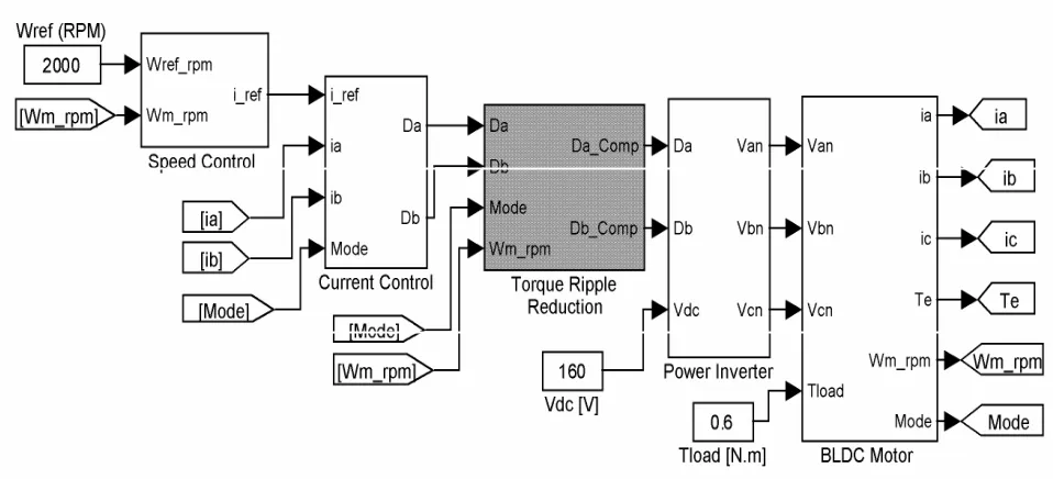
The performance of the system is simulated at speed 2000 rpm. Fig. 13 shows the current waveforms in both cases with and without applying the proposed torque ripple reduction technique. Current ripple reaches to 2.5 [A] (about 40%) that is high. Using the developed technique it reduces to lower than 7%.
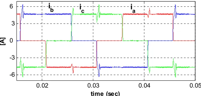
Fig. 14 shows the electromagnetic torque without and with applying the proposed technique. In simulation, DC-link voltage of the inverter has set to 160 [V] and at speed ω=2000 rpm, back-EMF voltage becomes 22.4 [V] and so, E/V ratio is between 1/8 and 3/8. Fig. 15 shows the current commutation in mode II (IV) without using the developed torque ripple reduction method. It
is obvious that there is not any commutation torque ripple. It is because of that, ω=2000 rpm is located at low speed range of mode II and as stated earlier, DPC control method can eliminate commutation torque ripple in case C. However, for modes IV (I) and VI (III) as stated in Eq. (26) and Eq. (30), operation point ω=2000 rpm is located at high speed range (case B) of these modes and it is prospected that commutation torque ripple occurs.
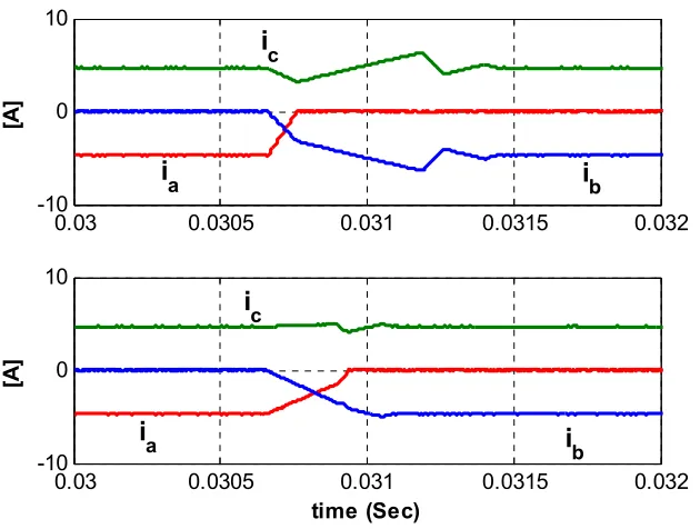
Fig. 16 shows the commutation ripple reduction in mode IV. Using developed technique significantly reduces the current ripple and current slopes become equal together. Fig. 17 shows the switching command to switch S1 that is set to 56%. DPC controller commands switch S1 to be zero, but developed torque ripple reduction method, during commutation modifies it to 56%. Fig. 18 shows the current waveforms in mode VI. Applying the proposed technique reduces the current ripple significantly.
Table 1 Rated Parameters of BLDC Motor.
Prated 1 [hp] ωrated 3500 [RPM]
R 0.75 [Ω] Ls-M 3.05 [mH]
Kt 0.21 [N.m/A] Ke 0.107 [V/(rad/sec)]
Irated 10 [A] VDC-Bus 160 [V]
Zp 2 J 8.2e-5 [Kgm
2 ]
Fig. 12 Block diagram of the FSTPI-BLDC motor drive with new commutation torque ripple reduction technique.
0.02 0.03 0.04 0.05 -6
-3 0 3 6
time (sec)
[A
]
i
b
i
ci
a(a) Without applying the torque ripple reduction
0.02 0.03 0.04
-6 -3 0 3 6
time (Sec)
[A
]
i
b
i
ci
a(b) With applying the torque ripple reduction
Fig. 13 Phase current waveforms of the BLDC motor with/without torque ripple reduction
0.015
0.025
0.035
0.045
0.5
1
1.5
[N
.M
]
Without torque ripple reduction
0.015
0.025
0.035
0.045
0.5
1
1.5
time (Sec)
[N
.M
]
With torque ripple reduction
Fig. 14 Developed electromagnetic torque in different modes.
0.035-6 0.0355 0.036 -3
0 3 6
time (sec)
[A
]
Phase Currents
i
b
i
c
i
aFig. 15 Current commutation in mode II without using torque ripple reduction.
0.015 0.0155 0.016 0.0165 0.017
-10 -5 0 5 10
[A
]
0.015 0.0155 0.016 0.0165 0.017
-10 -5 0 5 10
time (Sec)
[A
]
i b
i c i
a
ic
ia i
b
Fig. 16 Current commutation in mode IV.
0.01560 0.0157 0.0158
0.5 1
Without torque ripple reduction
0.01560 0.0157 0.0158
0.5 1
With torque ripple reduction
time (Sec)
Fig. 17 Applied switching command to S1 in mode IV.
0.03 0.0305 0.031 0.0315 0.032 -10
0 10
[A
]
0.03 0.0305 0.031 0.0315 0.032
-10 0 10
time (Sec)
[A
]
i
bi
ci
ai
ci
a
i
bFig. 18 Current commutation in mode VI.
7 Conclusion
This paper presents an analytical study on commutation torque ripple in a four-switch brushless DC motor drive. The analytic equations of commutation intervals and commutation torque ripple are obtained for each mode. Developed results show that phase commutation characteristics are different for each operation modes. It shows also the limit point of current control reduced to half of its corresponding point in a six-switch inverter. It means the accessible speed range that the phase currents can be regulated as rectangular is limited to half of nominal speed. Then, a new torque ripple reduction technique has been developed that is capable to eliminate the torque in entire speed range lower than current control limit point V=4E. Actually it is based on the slope equalization of the decaying and rising current in commutation interval. The validity of the developed method has been demonstrated via simulation. The proposed method enhances the performance of the FSTPI-BLDC motor drive and can be used for low cost applications.
References
[1] R. Krishnan; Electric Motor Drives: Modeling, Analysis and Control, Prentice-Hall of India, New Delhi, 2003.
[2] Jahns T. M., Soong W. L., “Pulsating Torque Minimization Techniques for Permanent Magnet AC Motor Drives---A Review,” IEEE Transactions on Industrial Electronics, Vol. 43, No. 2, April 1996, pp. 321-330.
[3] Joong-Ho Song, Ick Choy, “Commutation Torque Ripple Reduction in Brushless DC Motor Drives Using a Single DC Current Sensor,” IEEE Transactions on Power Electronics, Vol. 19, No. 2, March 2004, pp. 312-319.
[4] Carlson R., Mazenc M. L., Dos J. C., Fagundes S., “Analysis of torque ripple due to phase commutation in brushless DC machines,” IEEE Transactions on Industry Applications, Vol. 28, No. 3, May/June 1992, pp. 632-638.
[5] Lee B. K., Kim T. H., Ehsani M., “On the feasibility of four-switch three-phase BLDC motor drives for low cost commercial applications: topology and control,” IEEE Transactions on Power Electronics, Vol. 18, No. 1, pp. 164-172, January 2003.
[6] Lee J. H., Chan AHN S., Hyun D. S., “A BLDCM drive with trapezoidal back EMF using four-switch three phase inverter,” IEEE Industry Applications Conference, pp. 1705-1709, 2000. [7] Halvaei Niasar A., Moghbeli H., Vahedi A.,
“Modeling and Simulation Methods for Brushless DC Motor Drives,” International Conference on Modeling, Simulation and Applied Optimization, ICMSAO, pp.05-96/05-6, 2005, UAE.
[8] Kim G. H., Kang S. J., Won J. S., “Analysis of the commutation torque ripple effect for BLDCM fed by HCRPWM-VSI,” IEEE Applied Power Electronics Conference and Exposition, pp. 277-284, 1992.
Abolfazl Halvaei-Niasar, Ph.D. Student, Department of Electrical Engineering, Iran University of Science & Technology, Narmak, Tehran, Iran. Tel: +98 913 1635923, Fax: +98 21 77240490, EML: [email protected] He was born in Kashan, Iran in 1974. He received his B.Sc. and M.Sc. in 1998 and 2000 from Isfahan University of Technology (IUT) and University of Tehran (UT) both in electrical engineering respectively. He is now studying in Iran University of Science & Technology (IUST) for Ph.D. His research interests are mainly the control systems & instrumentation, DSP based control systems, electric drives, PM Brushless DC motor drives, sensorless drives. He is a student member of IEEE.
Abolfazl Vahedi, Associate Professor, Department of Electrical Engineering, Iran University of Science & Technology, Narmak, Tehran, Iran, Postal code: 16846-13114, Tel: +98 21 73912619, Fax: +98 21 77240490, EML: [email protected]
He was born in Tehran, Iran in 1966. He received his B.Sc., M.Sc. and Ph.D. in 1989, 1992 and 1996 from Ferdowsi Mashhad University, Institut Nationale Polytechnique de Lorraine (INPL-FRANCE) and INPL all in electrical engineering respectively. He has directed several projects in the area of conventional and special electric machines and drives. His research interests are mainly design, implementation and optimization of electric machines including traction motors and drives. He is a member of Center of excellence for power system automation and operation at Iran University of Science and Technology (IUST). He is also member of IEE and SEE.
Hassan Moghbeli, Visiting Assistant Professor at Qatar Department of Science and Mathematics, Texas A&M University, Po. Box 23874, Education City, Doha, Qatar, +974-4230198, and also Department of Electrical & Computer Engineering, Isfahan University of Technology, Isfahan, Iran. Tel: +98 218054034, EML: [email protected]
He was born in Isfahan, Iran in 1950. He received his B.Sc., M.Sc. and Ph.D. in 1973, 1978 and 1989 from Iran University of Science and Technology (IUST), Oklahoma State University and University of Missouri-Columbia (UMC) all in electrical engineering respectively. He has directed several projects in the area of electric drives, power systems, electric vehicles, hybrid electric and fuel cell vehicles and railway electrification. His research interests are electric drives, power electronics, and design of electric and hybrid electric vehicle. He is a member of IEEE, ASME, and SAE.