Please cite this article as:S.M. Varedi, H.M. Daniali, M. Dardel, A. Fathi, Dynamic Behavior Analysis of a Planar Four-bar Linkage with Multiple Clearances Joint, International Journal of Engineering (IJE), TRANSACTIONS B: Applications Vol. 28, No. 2, (February 2015) 243-250
International Journal of Engineering
J o u r n a l H o m e p a g e : w w w . i j e . i r
Dynamic Behavior Analysis of a Planar Four-bar Linkage with Multiple Clearances
Joint
S. M. Varedi*, H. M. Daniali, M. Dardel, A. Fathi
Department of Mechanical Engineering, Babol University of Technology, Babol, Iran
P A P E R I N F O
Paper history: Received 06July 2014
Received in revised form 28September2014 Accepted 13November 2014
Keywords:
Dynamic Four-bar Linkage Clearance Revolute Joint
A B S T R A C T
Clearances in the joints are inevitable in practicedue to tolerances, and defects arising from design and manufacturing. In the presence of clearance at a joint, a mechanism gains some additional, uncontrollable degrees of freedom which are the source of error. Moreover, joints undergo wear and backlashes and so cannot be used in precision mechanisms. In this study, the dynamic behaviour of a planar mechanism with revolute joints, in the presence of clearances is investigated. A continuous contact force model, based on the elastic Hertz theory together with a dissipative term, is used to evaluate the contact forces. Moreover, using a new contact model,the dynamic characteristics of planar mechanical system with multiple revolute joints in the presence of clearance are analyzed. Numerical results for four-bar linkage with one, two and three revolute clearance joints are presented and compared.
doi: 10.5829/idosi.ije.2015.28.02b.10
1. INTRODUCTION1
Parallel mechanisms have attracted the attention of many researchers. These mechanisms also have growing applications in robotics, machine tools, positioning systems, measurement devices, and so on [1-3]. It has been proved that such a closed-loop mechanism has great potential and advantages over the traditional opened-loop mechanism. The main advantage of parallel mechanisms is the high positioning accuracy due to their inherent rigidity [4]. But, due to joint clearance, a parallel mechanism’s end-effector exhibits position and orientation (or collectively referred to as pose) errors of various degrees [5].
Clearances in mechanisms are unavoidable due to wear, assembly and manufacturing tolerances. Performances of mechanisms in reality are deviated from the ideal mechanisms due to joint clearances [6]. In addition, joint clearance can lead to impulsive forces. These forces not only create increasing vibration amplitude, but also reduce system reliability, stability and life. Thus, joint clearance changes the dynamic
1*Corresponding Author’s Email:[email protected](S.M. Varedi)
response of a system. This justifies the deviations between the numerical predictions and the experimental measurements [6]. Therefore, these errors must be tightly controlled to ensure the desired performances. The problem of modeling joints with clearance in the context of multi body dynamics has been the subject of many studies during the last few decades [6-10]. Most of the reported work is devoted to the analysis of linkages [11-21], while the reported work on the synthesis of linkages is comparatively limited [22-24].
The main purpose of the present work is to study the dynamic behaviour of planar four-bar linkage with rigid links in the presence of clearance in the multiple revolute joints. Different cases are considered with the purpose of performing a parametric study for quantifying the influence of the number of clearance joints on the dynamic responses of multi body systems with multiple clearance joints. In joints with clearances, if there is no lubricant, the journal moves freely inside the bearing boundaries until it contacts with the bearing. When the journal and the bearing are in contact, deformation takes place at the contact zone resulting in a contact force normal to the plane of collision.
(a) (b)
journal motion inside the bearing
This force can be formulated by a non-linear continuous model proposed by Lankarani and Nikravesh [16]. The friction effects due to relative tangential velocity on the contact zone are also modeled according to the modified Coulomb friction law [25]. Therefore, the normal and tangential forces are introduced into the equations of motion of the system for the contact mode. A numerical simulation is included to illustrate the effects of clearances in several joints.
2. LITERATURE REVIEW
Dubowsky and Freudenstein [11, 12] formulated an impact pair model to predict the dynamic response of an elastic mechanical joint with clearance. Earles and Wu [13] introduced a model based on permanent contact condition. In their model, clearance is replaced by a mass-less virtual link that connects the journal center to the bearing center. Grant and Fawcett [14] analyzed the effects of lubrication, material properties and clearance size on the contact loss in a four-bar mechanism having joint clearance. Experimental results confirmed the validity of the proposed theoretical approach. Bengisu et al. [15] developed a separation parameter for a four bar mechanism based on a zero-clearance analysis. They also predicted contact-loss in a mechanism with multiple joint clearances. Using the general trend of the Hertz contact law, Lankarani and Nikravesh developed a contact force model in which a hysteresis damping function was incorporated with the intent to represent the energy dissipated during the impact [16]. Flores and Ambro'sio [17] used contact force approach to model and simulate the performance of a slider–crank mechanism with one clearance-joint. Also, Flores et al. [18] studied the effect of friction between the journal and the bearing, using a modified coulomb’s friction law. Schwab et al. [19] compared several models of contact forces. They analyzed and simulated a slider-crank mechanism with one clearance-joint of rigid or flexible connecting rod, for both dry and lubricated contact conditions. Ting et al. [20]studied the effects of
the joint clearance on position and orientation deviation of mechanisms and robotic manipulators, using mass-less virtual link approach to model the clearances. Zhu and Ting [21] made the uncertainty analysis of planar and spatial robots with clearance joints. Feng et al.
inertia forces by re-distribution of masses of the moving links in planar mechanisms, in the presence of
Genetic Algorithm Method to find the optimized link parameters for the path generation problem in the presences of clearance. Moreover, Zhang and Huang [24] made a robust tolerance design for function generation mechanisms.
3. MODELING OF REVOLUTE JOINTS WITH CLEARANCE
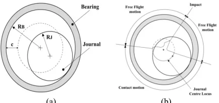
Figure 1(a) shows the typical configuration of a revolute joint with clearance. The joint elements are the bearing and journal, withdiameters RB and RJ, respectively. The
radial clearance, c, is the difference between their radii. It is noteworthy that the existence of clearance in revolute joints introduces two extra degrees of freedom, that is, the horizontal and vertical displacements of the center of the journal and consequently, the journal and bearing can freely move relative to each other. They experience three different modes of relative motion; namely, contact mode, free flight mode and impact mode, as illustrated in Figure 1(b). In the contact mode, the journal and the bearing are in permanent contact and only a sliding or rolling relative motion is assumed. Clearly, this mode is terminated when the journal loses the contact with the bearing, i.e. the free flight mode is started. If this is the case, the journal can move freely inside the bearing boundaries; i.e., there is no contact between the journal and the bearing. Therefore, no reaction force is developed at the joint.
Finally, in the impact mode, which occurs at the termination of the free-flight mode, there is an impact force between the journal and bearing. This causes a discontinuity in the kinematic and dynamic characteristics of the system. At the termination of the impact mode, the journal can enter either in free flight or in contact modes. It is noteworthy that in the contact mode, there is the normal contact force FN and the
tangential contact force FT between the journal and
bearing as illustrated in Figure 2(b),while, in the case of no contact between the journal and the bearing, the contact forces vanishes [1, 2], i.e.,
î í ì
³ ¹
< =
+ =
0 0
0 0
,
d d if
if
T
N F
F F F
F (1)
Figure 1. (a) Revolute joint with clearance (b) modes of the
[22] developed an optimization method to control the
whered is the relative penetration depth as depicted in Figure 2(a) and is given as:
c e -=
d (2)
in which
e
is the absolute eccentricity defined as:2
2 Y
X
e= D +D (3)
whereDXand DYrepresent, respectively the horizontal and vertical displacements of the journal with respect to the bearing.
Moreover, the magnitude of the joint force can be obtained from the Hertzian contact theory under the assumption that the dimension of the contact region between the journal and bearing is much smaller than the radius of the bearing. The contact force model proposed by Lankarani and Nikravesh[10] that accounts for both the elastic and damping effects is employed in the present work. It is noteworthy that the damping effect is associated with the energy dissipated during the impact together with the dissipative effect associated with the Coulomb friction on the contact surface [23]. Thus, the normal reaction force at the revolute joint in the presence of clearance can be expressed by [6, 16]:
. d d D K
F n
N= + (4)
whereKis the generalized stiffness parameter, depending on the geometry of the contacting surfaces and their physical properties, while D is the hysteresis damping coefficient. Therefore, the first term in the right hand side of Equation (4) represents the elastic force based on the Hertz contact law while the second term accounts for the damping force due to energy dissipation. Also,
n
is a constant depending on the material properties of the contact surface. For the contacting bodies,Kis given as [6]:( ) i j j i j
i R R
R R K + + = s s 3 4 (5)
Here,siand sj are defined as:
j i k Ek
k
k , ,
1 2
=
-= u
s (6)
where
u
kandE
kare the Poisson's ratio and the Young's modulus of each body, respectively. Moreover, the hysteresis damping coefficient is given by [6]:n
D=cd (7)
in which the hysteresis factorcis defined as:
(
)
i e c K . 2 4 1 3 dc= - (8)
where i
.
d and ce are the initial impact velocity and the
restitution coefficient, respectively. Substituting the values ofKandDfrom Equations (5) and (7) into Equation (4) yields [6]:
( ) ÷÷ ÷ ø ö çç ç è æ -+ = i e n N c K F . . 2 4 1 3 1 d d d (9)
In addition, for tangential contact force
F
T , Ambrósio presented a modification for the Coulomb's friction law expressed as follows [25]:T T N f d T v v F c c
F =- (10)
where
v
Tis the relative tangential velocity;c
f is the friction coefficient and the dynamic correction coefficientc
dis given as:ï ï î ï ï í ì > £ £ -< = 1 1 0 0 1 0 0 1 0 v v v v v v v v v v v c T T T T d (11)
in which
v
0andv
1are given bounds for the tangential velocity. Finally, in the contact mode, Qc and ψ areobtained from the following equation, while in the non-contact mode Qc is zero [6].
(
)
y a jd d
d = +
÷÷ ÷ ø ö çç ç è æ -+ = , 4 1 3 1 . . 2 2 / 3 i e eq C c K Q (12) in which: K c c Keq= 1+ 2f+ d2
÷ ÷ ÷ ÷ ø ö ç ç ç ç è æ -+ -+ = -B B J J B B J J d f R R r R R r c c w w a w w a j . . 1 tan (13)
where
w
JandwBare the journal and the bearing angular velocities, respectively.
(a) (b)
Figure 2. (a) Revolute joint with clearance (b) Joint contact forces
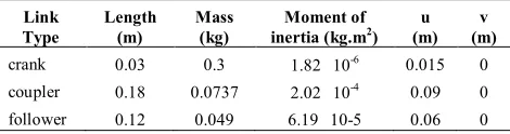
TABLE 1. Geometric and inertial properties of the four-bar mechanism Link Type Length (m) Mass (kg) Moment of
inertia (kg.m2) (m) u (m) v
crank 0.03 0.3 1.82 10-6 0.015 0
coupler 0.18 0.0737 2.02 10-4 0.09 0
TABLE 2. The clearance geometric and material properties
Bearing
radius clearance size Restitution coefficient modulus Young's Poisson's ratio coefficient Friction
10 (mm)
1 (mm)
0.9 207
(Gpa)
0.3 0
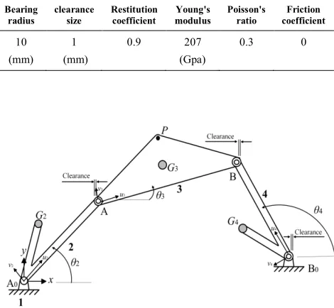
Figure 3. Four-bar linkage with three revolute clearance joints
4. EQUATIONS OF MOTION
The dynamics model of a four-bar mechanism is established considering the clearance model. The clearance of joint leads to several different motion phases of bodies connected with the clearance joint: one is that the bodies move free in the clearance, and the other is that the bodies contact and interact. So the mechanism system with clearances between bodies is a variable topology system.This variable topology system of mechanism is solved using the dynamic segmentation modeling method. The dynamic equation is obtained using the Lagrange multiplier method.In the free motion phase, the dynamic equation is [26]:
0 ) , ( ,
. ..
= =
+ +
+ q q qt
q T
q f φ
φ K C
M l (14)
whereqis the generalized coordinate column matrix,M, CandKthe generalized mass matrix, generalized damp matrix and generalized stiffness matrix, respectively,φq the Jacobin matrix of constraint equation,fthe generalized force matrix and
l
the Lagrange multiplier column matrix.In contact phase, the bodies contact and interact. Thus, the contact forces exist in the clearances. The dynamic equation is [26]:0 ) , ( ,
. ..
= +
= + +
+ q q qt
q T
q f F φ
φ K C
M l (15)
whereFis the contact force relative toq, which contains both normal contact force
F
Nand tangential friction force FT(Equation (1)).5. CASE STUDY
In this section, the four-bar linkage is used to demonstrate the effect of clearance joint on the dynamics of the mechanism. The kinematic model of the mechanism with three clearance joints is depicted in Figure 3. The links are assumed to be rigid.
This mechanism will be analyzed here, in several cases; i.e., "a". One clearance joint, (only joint A is with clearance and the other joints are ideal),
"b". Two clearance joints, (joints A and B are with clearances and joints A0 and B0 are ideal),
"c". Three clearance joints, (all the joints have clearances, except joint A0 that is ideal).
It is noteworthy that each clearance, add two degree-of- freedoms (DOF) to the mechanism. Therefore, the 1-dof four bar linkage in the ideal case has 3-DOF, 5-DOF and 7-DOF, for the cases "a", "b" and "c", with the followings generalized coordinates, respectively.
{
2 3 4}
1= q ,q ,q
q q2=
{
q2,xG3,yG3,q3,q4}
{
2 3 3 3 4 4 4}
3 ,xG ,yG , , ,xG ,yG
q = q q q (16)
whereqi(i=2,3,4) are the angles of the links relative to the horizontal axis;
x
Giandy
Gi(i=3,4) are the coordinates of the mass centers of the connecting rod and the follower in the fixed coordinate system.The geometric and inertial properties of the mechanism are listed in Table 1; while the bearing radius, the magnitude of the clearance and material properties associated with the journal and the bearing are listed in Table 2. The clearances and bearings radii are the same for all the joints, while the length of
0
0B
A is 0.2m.
Furthemore, for the tolerances we used 1e-20 for 'AbsTol', 1e-12 for 'RelTol' and 1e-10 for 'InitialStep'. Finally, we include a dynamic simulation for the mechanism in these three cases wherein the crank is rotated with a constant angular velocity of 5000 rpm, while initially the journal and the bearing centers are coincident. The values of clearance vector in joint A, for the three cases, are plotted in Figure 4.
One clearance joint
Two clearance joints
Three clearance joints
Figure 4. Values of clearance vectors in joint A
One clearance joint
Two clearance joints
Three clearance joints
It has been revealed that for one clearance joint, the value is a smooth function of the time, while this is not true for two other cases. Therefore, one can expect higher contact forces in these cases. The values of the contact forces in joint A are depicted in Figure 5 and compared with the case without clearance.
The plots clearly show that in the mechanism with joint clearance, the contact forces experience some sharp changes for cases "b" and "c". Further, the value of the contact force increases with increasing the number of clearance joints. It is noteworthy that the maximum value of the contact force in joint A, for cases "a", "b" and "c" is 1.4, 3.7 and 5.2-folds compared to the case without clearance.Therefore, one should expect much worse dynamic performance for the mechanisms with more clearance joint.
The value of the required input torque is depicted in Figure 6 which indicates that the required input torque experiences sudden changes.
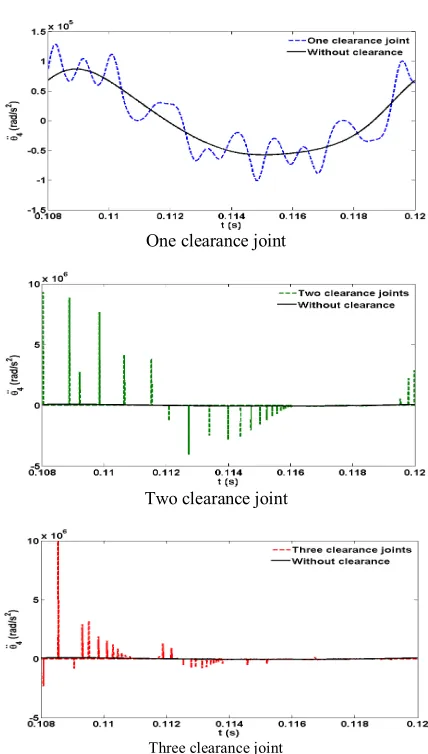
Additionally, the value of angular acceleration of the coupler and the follower are depicted in Figures 7 and 8, respectively. The plots for case "b" and "c" show sharp changes, while for case "a" the plots are smooth. It is noteworthy that higher values of the accelerations lead to higher inertia forces which act as the source of shocks and vibrations.
All the plots shown in Figures 4 - 8 clearly reveal the undesirable effect of the increase of the number of clearance joints on the dynamic performance of the four-bar linkage.
One clearance joint
Two clearance joint
Three clearance joint
One clearance joint
Two clearance joint
Three clearance joint
Figure 7. The angular acceleration of the coupler
One clearance joint
Two clearance joint
Three clearance joint
Figure 8. The angular acceleration of the follower
6. CONCLUSIONS
force model, the normal contact forces inthe revolute joints with clearance have been formulated. While the tangential friction forces have been modeled using a modified Coulomb friction coefficient. From numerical simulation, it can be concluded that the system response substantially changes when the number of clearance joints increase. These changes are mainly due to higher values for the contact forces and links accelerations that cause shocks and vibrations in the mechanism.
7. REFERENCES
1. Fattah, A. and Ogbaei, M., "Forward position kinematics of a parallel manipulator with new architecture", International
Journal of Engineering, Transactions B: Applications, Vol.
14, No. 3, (2001), 239-246.
2. Varedi, S., Daniali, H. and Ganji, D., "Kinematics of an offset 3-UPU translational parallel manipulator by the homotopy continuation method", Nonlinear Analysis: Real World
Applications, Vol. 10, No. 3, (2009), 1767-1774.
3. Liang, Q. and Wang, Y., "Flexible ankle based on PKM with force/torque sensor for humanoid robot", International Journal
of Engineering, Transactions B: Applications, Vol. 24, No. 4,
(2011), 377-385.
4. Dasgupta, B. and Mruthyunjaya, T., "The stewart platform manipulator: A review", Mechanism and Machine Theory, Vol. 35, No. 1, (2000), 15-40.
5. Meng, J., Zhang, D. and Li, Z., "Accuracy analysis of parallel manipulators with joint clearance", Journal of Mechanical
Design, Vol. 131, No. 1, (2009), 11-13.
6. Bai, Z.F. and Zhao, Y., "Dynamic behaviour analysis of planar mechanical systems with clearance in revolute joints using a new hybrid contact force model", International Journal of
Mechanical Sciences, Vol. 54, No. 1, (2012), 190-205.
7. AzimiOlyaei, A. and Ghazavi, M.R., "Stabilizing slider-crank mechanism with clearance joints", Mechanism and Machine
Theory, Vol. 53, (2012), 17-29.
8. Behzad, M. and Asayesh, M., "Vibration analysis of rotating shaft with loose disk", International Journal of Engineering
Transaction B: Applications, Vol. 15, No. 4, (2002), 385-393.
9. Flores, P., "A parametric study on the dynamic response of planar multibody systems with multiple clearance joints",
Nonlinear Dynamics, Vol. 61, No. 4, (2010), 633-653.
10. Sardashti, A., Daniali, H. and Varedi, S., "Optimal free-defect synthesis of four-bar linkage with joint clearance using PSO algorithm", Meccanica, Vol. 48, No. 7, (2013), 1681-1693. 11. Korrani, M.A. and Mahani, M.F., "Dynamic analysis of a
three-rotor flexible coupling with angular misalignment",
International Journal of Engineering-Transactions B:
Applications, Vol. 24, No. 2, (2011), 155-164.
12. Dubowsky, S. and Freudenstein, F., "Dynamic analysis of mechanical systems with clearances—part 1: Formation of dynamic model", Journal of Manufacturing Science and
Engineering, Vol. 93, No. 1, (1971), 305-309.
13. Dubowsky, S. and Freudenstein, F., "Dynamic analysis of mechanical systems with clearances—part 2: Dynamic response", Journal of Manufacturing Science and
Engineering, Vol. 93, No. 1, (1971), 310-316.
14. Earles, S. and Wu, C., "Motion analysis of a rigid link mechanism with clearance at a bearing using lagrangian mechanics and digital computation", Journal of Mechanisms, (1973), 83-89.
15. Grant, S. and Fawcett, J., "Effects of clearance at the coupler-rocker bearing of a 4-bar linkage", Mechanism and Machine
Theory, Vol. 14, No. 2, (1979), 99-110.
16. Bengisu, M., Hidayetoglu, T. and Akay, A., "A theoretical and experimental investigation of contact loss in the clearances of a four-bar mechanism", Journal of Mechanical Design, Vol. 108, No. 2, (1986), 237-244.
17. Lankarani, H. and Nikravesh, P., "A contact force model with hysteresis damping for impact analysis of multibody systems",
Journal of Mechanical Design, Vol. 112, No. 3, (1990),
369-376.
18. Flores, P. and Ambrósio, J., "Revolute joints with clearance in multibody systems", Computers & Structures, Vol. 82, No. 17, (2004), 1359-1369.
19. Flores, P., Ambrosio, J., Claro, J.C.P., Lankarani, H. and Koshy, C., "A study on dynamics of mechanical systems including joints with clearance and lubrication", Mechanism and Machine
Theory, Vol. 41, No. 3, (2006), 247-261.
20. Schwab, A., Meijaard, J. and Meijers, P., "A comparison of revolute joint clearance models in the dynamic analysis of rigid and elastic mechanical systems", Mechanism and Machine
Theory, Vol. 37, No. 9, (2002), 895-913.
21. Ting, K.-L., Zhu, J. and Watkins, D., "The effects of joint clearance on position and orientation deviation of linkages and manipulators", Mechanism and Machine Theory, Vol. 35, No. 3, (2000), 391-401.
22. Zhu, J. and Ting, K.-L., "Uncertainty analysis of planar and spatial robots with joint clearances", Mechanism and Machine
Theory, Vol. 35, No. 9, (2000), 1239-1256.
23. Feng, B., Morita, N. and Torii, T., "A new optimization method for dynamic design of planar linkage with clearances at joints— optimizing the mass distribution of links to reduce the change of joint forces", Journal of Mechanical Design, Vol. 124, No. 1, (2002), 68-73.
24. Erkaya, S. and Uzmay, I., "Determining link parameters using genetic algorithm in mechanisms with joint clearance",
Mechanism and Machine Theory, Vol. 44, No. 1, (2009),
222-234.
25. Huang, X. and Zhang, Y., "Robust tolerance design for function generation mechanisms with joint clearances", Mechanism and
Machine Theory, Vol. 45, No. 9, (2010), 1286-1297.
Dynamic Behavior Analysis of a Planar Four-bar Linkage with Multiple Clearances
Joint
S. M. Varedi, H. M. Daniali, M. Dardel, A. Fathi
Department of Mechanical Engineering, Babol University of Technology, Babol, Iran
P A P E R I N F O
Paper history: Received 06 July 2014
Received in revised form 28September 2014 Accepted 13November 2014
Keywords:
Dynamic Four-bar Linkage Clearance Revolute Joint
هﺪﯿﮑﭼ
ﻞﯿﻟدﻪﺑ ﺲﻧاﺮﻠﺗدﻮﺟو ،ﺖﺧﺎﺳﺪﻨﯾاﺮﻓرددﻮﺟﻮﻣﺐﯾﺎﻌﻣوﺎﻫ
ﻞﻤﻋرد بﺎﻨﺘﺟايﺮﻣاﻞﺻﺎﻔﻣردﯽﻘﻟدﻮﺟو ﺖﺳاﺮﯾﺬﭘﺎﻧ
.
ﺪﯾﺎﺑ
ﯽﻣﻪﮐلﺮﺘﻨﮐﻞﺑﺎﻗﺮﯿﻏيدازآﻪﺟردﺪﻨﭼ،ﻞﺼﻔﻣردﯽﻘﻟدﻮﺟوترﻮﺻردﻪﮐدﻮﻤﻧﻪﺟﻮﺗ ﺎﻄﺧدﺎﺠﯾاﻊﺒﻨﻣﺪﻧاﻮﺗ
ﻪﺑ،ﺪﺷﺎﺑ
ﺪﺷﺪﻫاﻮﺧهدوﺰﻓامﺰﯿﻧﺎﮑﻣ
.
ﺲﭘوﺶﯾﺎﺳدﻮﺟو،ﻦﯿﻨﭽﻤﻫ ﯽﻣﺶﻫﺎﮐارمﺰﯿﻧﺎﮑﻣﺖﻗد،ﻞﺼﻔﻣردﯽﻧز
ﺪﻫد
.
،ﻪﻟﺎﻘﻣﻦﯾارد
ﻪﺤﻔﺻمﺰﯿﻧﺎﮑﻣﮏﯾﯽﮑﯿﻣﺎﻨﯾدرﺎﺘﻓر ﯽﻣراﺮﻗﯽﺳرﺮﺑدرﻮﻣنآﯽﯾﻻﻮﻟﻞﺻﺎﻔﻣردﯽﻘﻟﻦﺘﻓﺮﮔﺮﻈﻧردﺎﺑيا
دﺮﯿﮔ
.
لﺪﻣياﺮﺑ
-ﺗﻪﮐيﺪﯾﺪﺟيرﻮﺌﺗزا،ﯽﺳﺎﻤﺗيوﺮﯿﻧيزﺎﺳ ﺖﺳاهﺪﺷهدﺎﻔﺘﺳا،ﺖﺳاﯽﯾاﺮﯿﻣﻪﻠﻤﺟوﺰﺗﺮﻫيرﻮﺌﺗزاﯽﺒﯿﮐﺮ
.
لﺎﺜﻣناﻮﻨﻋﻪﺑ
ﻪﺼﺨﺸﻣ،يدﺪﻋ ﻪﻠﯿﻣرﺎﻬﭼمﺰﯿﻧﺎﮑﻣﯽﮑﯿﻣﺎﻨﯾديﺎﻫ
رادرﻮﻣﻖﻟﻞﺼﻔﻣﻪﺳوود،ﮏﯾياراديا ز
ﯽﻣراﺮﻗﻪﺴﯾﺎﻘﻣوﯽﺑﺎﯾ دﺮﯿﮔ
.
ﯽﻣنﺎﺸﻧﺞﯾﺎﺘﻧ ﺗوﺶﻫﺎﮐﺰﯿﻧﺎﮑﻣﯽﮑﯿﻣﺎﻨﯾدﯽﯾارﺎﮐ،ﻖﻟﻞﺻﺎﻔﻣداﺪﻌﺗﺶﯾاﺰﻓاﺎﺑﻪﮐﺪﻨﻫد
ﺶﯾاﺰﻓانآردشﺎﻌﺗراوكﻮﺷﺪﯿﻟﻮ
ﯽﻣ ﺪﺑﺎﯾ
.