Reduction of Machine Setup Time
Janez Kušar* - Tomaž Berlec - Ferdinand Žefran - Marko Starbek University of Ljubljana, Faculty of Mechanical Engineering, SloveniaCustomers today require smaller series of products. In manufacturing companies, this increases machine setup time, which is a waste.
This paper presents a procedure for organizing and implementing a reduction of machine setup time. It is based on teamwork and uses the SMED method, which allows a gradual reduction of machine setup time to less than 10 minutes, and a continuous improvement system.
The paper also presents the results of the organization and execution of a SMED workshop for the reduction of setup times in a jet machine, as well as first suggestions for improvements that should significantly reduce machine setup time.
©2010 Journal of Mechanical Engineering. All rights reserved.
Keywords: machine setup time, SMED workshop, continuous improvement, teamwork, microelements
0 INTRODUCTION
In the 1950s, Taiichi Ohno, the legendary president of Toyota, was very unhappy because his company produced cars for stock. The cars were driven from the manufacturing hall to a parking lot, where they waited for customers. T. Ohno considered that this waiting of cars for customers was a waste that should be eliminated, or at least reduced. He found that the waste was caused by manufacturing components and final products (cars) in excessively large series.
The equation for calculating the time required for manufacturing a series of parts and the assembly of components is:
t = ts + m · t1 (1)
where:
t time required for manufacturing parts and assembling components [Nh/series]
ts machine setup time or assembly workplace setup time [Nh/series]
m number of units within a series
[pieces/series]
t1 manufacturing/assembly time per unit [Nh/piece].
Analysis of this equation led Ohno to the conclusion that the company could make a transition from large series manufacturing to small series only if they could substantially reduce the setup times of machines and assembly workplaces.
The task of finding a suitable method for reducing setup time was given to Shigeo Shingo, who is the author of the rapid machine setup method, also known as SMED (single minute exchange of dies) [1].
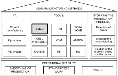
The SMED method is one of the lean manufacturing methods or tools [1], which allow successful competition in domestic and foreign markets (Fig. 1).
Van Goubergen says [2] that it is very important to reduce machine setup time during the implementation of lean manufacturing because this time has a significant impact on manufacturing costs due to decreasing sizes of series orders.
Van Goubergen justifies the reduction of machine setup time by [2]:
SMOOTHING OF PRODUCTION
STANDARDIZED
WORK KAIZEN
OPERATIONAL STABILITY
Pull system KANBAN 5S 5W problem based Solution of the
on the cause
Cycle time PRODUCTIONCELL VSM ANDON manufacturingStopping the
Current
manufacturing SMED TPM POKA YOKE Detection of errors
JIT: TOOLS: STOPPING THE
PRODUCTION PROCESS: LEAN MANUFACTURING METHODS
greater flexibility of the company (the company can offer customers more products and their variants in smaller series ),
higher throughput through company
bottlenecks (reduced setup times of bottleneck machines ensure higher throughput),
increased efficiency of the company (by reducing machine setup time, the efficiency of these machines increases, which increases company income).
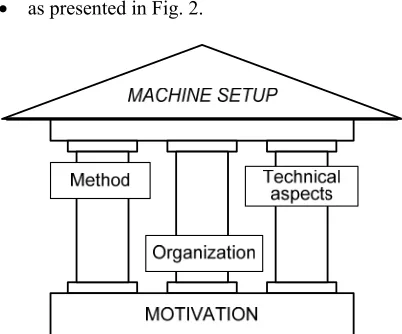
The quality of machine setup is defined by three parameters [2]:
the method used for machine setup (how),
organization of work needed for machine setup (who, what, when),
technical aspects of tools and devices,
as presented in Fig. 2.
Fig. 2. Elements of machine setup
Rapid and efficient machine setup requires optimal values of all three elements of machine setup, supported by the motivation of the personnel that carry out machine setup.
Quality and machine setup time also depend on machine design.
A company can select one of three options [3] to [ 5]:
design of a new machine that will ensure minimum setup time - large investment,
improvement of an existing machine and the use of the SMED method to achieve a setup time of 3 minutes,
use of the SMED method to achieve a setup time of less than 10 minutes.
Fig. 3 shows the relations between machine setup time and costs with these three strategies [3].
It can be seen from Fig. 3 that a reduction of machine setup time using the SMED method is cheap, but has only limited effects. The design of a new machine is expensive, but the new setup time will be very short. Taking into account both costs and setup time, it is most efficient for the company to select the SMED method and to make improvements to the machines.
Costs
desig n of
a n ew m
achin e
Fig. 3. Dependency between machine setup time and costs
1 ORGANIZATION AND EXECUTION OF SMED WORKSHOP
The goal of a SMED workshop is to reduce machine setup time and thus increase machine availability.
Experience in using the SMED method has shown that teamwork is essential for its successful implementation. When selecting team members to participate in the organization and execution of a SMED workshop, it is necessary to ensure that all nine team roles defined by Dr. Belbin are occupied [6].
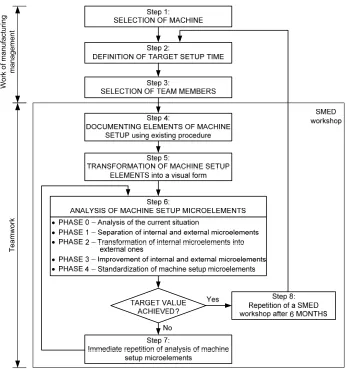
A review of the literature [3], [7] and [8] and our experience obtained in introducing the SMED method in companies have led us to the creation of a procedure for the organization and execution of a SMED workshop for the reduction of machine setup time (Fig. 4).
Wor
k of m
anufa
cturing
ma
nagem
ent
T
eam
work
Fig. 4. Procedure for the organization and execution of a SMED workshop
Step 1: SELECTION OF THE MACHINE Manufacturing management selects the machine for reduction of setup time by taking into account the pre-defined criteria (e.g., the longest machine setup time, frequency of setup, bottleneck machines).
Selection is made on the basis of ABC analysis [9].
Step 2: DEFINITION OF TARGET SETUP TIME
The definition of the target value for reduced setup time is very important, since it directly influences the motivation of team members who will carry out the SMED method.
Manufacturing management usually specifies that the team should reduce the setup
time by 50% during the first SMED workshop (Fig. 5).
It is difficult to improve this result in each consecutive SMED workshop, except when a new team member appears with revolutionary (and not too expensive) ideas [10] and [11].
Step 3: SELECTION OF TEAM MEMBERS
Team members that will participate in the execution of a SMED workshop are selected by the manufacturing management. The team should include representatives from manufacturing planning and management departments, workers who are responsible for machine setup and processing of orders, and maintenance personnel.
After carrying out the Belbin test of team roles [12] the manufacturing management appoints:
a TEAM LEADER, responsible for leading the team, organization and documentation of team sessions and for achieving agreement within the team,
a TEAM MODERATOR, who is the SMED
method expert and who will lead the team from step 4 to step 7 of the SMED workshop,
other team members:
o a setup operator, who will carry out the machine setup as it has been done up to that point,
o a protocol writer, who will take notes on machine setup elements,
o a time recorder operator, who will record the time required for machine setup elements,
o a photographer, who will take photos of details of machine setup elements,
o a cameraman, who will use a video camera to film the execution of all machine setup
elements,
o a team member to draw a diagram of the path made by the setup operator.
Manufacturing management informs the selected team members and their heads about the date of the SMED workshop. They confirm their approval by signing the "SMED workshop order" form (Table 1).
Step 4: DOCUMENTING ELEMENTS AND MICROELEMENTS OF MACHINE SETUP USING THE EXISTING PROCEDURE
The existing machine setup procedure is carried out and documented. The actual sequence and execution time of machine setup elements/microelements are defined.
The following tools are available for documenting the elements and microelements of machine setup:
notebook of machine setup elements,
monitoring paper,
list of paths made by the machine setup operator,
photos of machine setup details,
video film of the entire machine setup process.
A notebook with the elements and microelements of the machine setup is the simplest tool for documenting the sequence and timing of setup elements/microelements. The protocol writer enters the elements and microelements of the machine setup in the notebook.
The data are entered in the exact sequence of the setup, with the exact times noted, as reported by the time recorder operator.
Table 1. SMED workshop order
SMED workshop order Ordered by:
Workshop name
Workshop date from to
Workshop goals
Management: Signature: Team members: Department: Signature:
: : : : :
Date of meeting:
The monitoring paper is a form on which the protocol writer enters the following data:
sequential numbers of machine setup elements and microelements,
short description of machine setup elements and microelements,
cumulative times of machine setup elements and microelements,
individual times of machine setup elements and microelements,
histogram of individual times of machine setup elements and microelements.
The purpose of the list of paths made by the setup operator is to visualize unnecessary movements of the operator during setup. The basis for the list of paths is a drawing of the workplace. The movements of the setup operator are drawn onto it with a continuous line.
During thr subsequent analysis of the elements and microelements of the machine setup and on the basis of the list of actual paths made by the setup operator, the team can establish necessary paths and eliminate unnecessary ones.
Photos of details of machine setup elements and microelements are taken with a high-definition digital camera with zoom. The photographer should be careful not to be in the way of the setup operator.
A video camera is the most effective tool for recording the machine setup. For this purpose, a camera with a hard disk capacity of at least 120 GB and a battery for at least 50 hours of filming is required. Filming starts at the beginning of the execution of the first machine setup element/microelement and ends with the completion of the last element (without interruption). SMED team members can view the machine setup video several times and analyze it thoroughly.
Step 5: TRANSFORMATION OF MACHINE SETUP ELEMENTS AND MICROELEMENTS INTO A VISUAL FORM
The data obtained on the machine setup elements and microelements are copied from the notebook to stickers that can be affixed to a panel during the next step.
Step 6: ANALYSIS OF MACHINE SETUP ELEMENTS AND MICROELEMENTS
Analysis of machine setup elements and microelements is carried out by the team in a
room with a large panel, which allows the affixing of stickers, and chairs placed around in a semicircle.
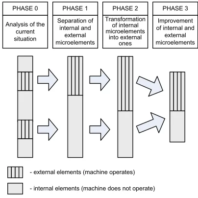
Analysis is carried out in a sequence of phases as presented in Fig. 6.
PHASE 0
Analysis of the current situation
PHASE 2 Transformation
of internal microelements
into external ones PHASE 1
Separation of internal and
external microelements
PHASE 3
Improvement of internal and
external microelements
- external elements (machine operates)
- internal elements (machine does not operate)
Fig. 6. Analysis phases of setup elements and microelements
Phase 0: Analysis of the current situation Before the meeting, the team moderator brings into the meeting room all stickers of machine setup elements and microelements, with their duration times, labeled as X or E. An X label on the microelement sticker indicates that another microelement follows this one, while an E label denotes that this is the last microelement.
At the beginning of the session, the moderator projects onto the panel the analytical card for entering the current situation of machine setup. By affixing stickers onto the panel (with the agreement of the team members) the current situation of machine setup is obtained.
Phase 1: Separation of internal and external microelements
The moderator presents every microelement of a particular element in the current machine setup and the team members must decide whether the microelement is:
internal (it can be carried out only during machine shutdown) or
The moderator marks the stickers of internal microelements with red and those of external microelements with yellow.
Phase 2: Transformation of internal microelements into external ones
The moderator (with the cooperation of the team) moves the yellow stickers either to column 1 (starting activities) or to column 5 (completion activities).
Phase 3: Improvement of internal and external microelements
By carrying out several creativity workshops [12] the team obtains suggestions for improvements of internal and external microelements.
The moderator enters all improvements of machine setup microelements into the lower part of the analytical card ("improvements" field).
Phase 4: Standardization of machine setup microelements
In this phase, standardization of internal and external microelements is carried out, and a continuous improvement principle is put into effect.
Training is organized for setup operators, machine operators and maintenance workers. Machine setup according to the improved procedure is carried out at least three times during this training.
Step 7: IMMEDIATE REPETITION OF THE ANALYSIS OF ELEMENTS AND MICROELEMENTS
If the target setup time defined in step 2 has not been achieved, the team immediately repeats the analysis of machine setup microelements.
Step 8: REPETITION OF THE SMED WORKSHOP
Reduction of machine setup time is a never-ending process, so it is necessary to repeat the SMED workshop every six months and in this way get closer to the set goal of "achieving a machine setup time shorter than 10 minutes".
2 CASE STUDY OF JET-MACHINE SETUP TIME REDUCTION
The manufacturing management decided that the company would test the SMED workshop in order to reduce machine setup time.
Step 1: SELECTION OF THE MACHINE The manufacturing management used the following criteria during machine selection:
machine setup times in the last three months,
number of machine setups in the last three months.
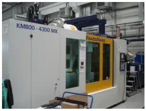
Using a weighted-scoring method, the manufacturing management decided that a reduction of setup time would be tested on a KM 800 – CNC Injection Molding Machine, Crauss-Maffei (Fig. 7).
Fig. 7. KM 800-CNC injection molding machine
Step 2: DEFINITION OF TARGET SETUP TIME
The time recorder operator measured the time required for machine setup: 119.97 minutes.
The manufacturing management decided that the target reduced setup time would be 60 minutes, i.e., 50% of the current value.
Step 3: SELECTION OF TEAM MEMBERS
The manufacturing management selected an 8-member team for the SMED workshop:
a team leader from the operation logistics department,
a team moderator from the technology department,
team members,
a setup operator from the manufacturing department,
Table 2. Monitoring paper - standard machine setup procedure
MONITORING PAPER
Element number
DESCRIPTION OF THE ELEMENT
Cumulative
time Individual time [sec]
HISTOGRAM OF INDIVIDUAL TIMES [sec]
hour minsec 10 20 30 40 50 60 70 80 90 100
1 Machine shutdown 0 00 31 31
2 Setup of the manipulat. 0 01 12 41 3 Walk to the office 0 01 26 14 4 Searching for documentation 0 01 35 9 5 Walk to the machine 0 01 50 15
:
:
: : : : : : : : : : : : : : : :
55 Confirmation of first samples 1 59 04 80
a time recorder operator from the
manufacturing department,
a photographer from the manufacturing department,
a cameraman from the supply department,
a drawer of paths made by the setup operator from the process control department.
The manufacturing management sent the "SMED-workshop order" form to departmental heads and team members for them to confirm their agreement with participation in the workshop.
Step 4: DOCUMENTING ELEMENTS AND MICROELEMENTS OF JET-MACHINE SETUP (existing procedure)
During the actual machine setup, the protocol writer entered the sequence of elements and microelements of machine setup into his notebook. He also noted exact setup times, reported by the time recorder operator.
After recording the machine setup elements, the protocol writer entered the data on the monitoring paper (Table 2).
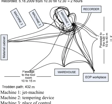
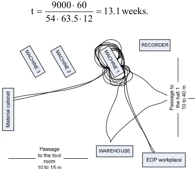
The drawer of the paths made by the setup operator made a drawing of the operator's movements. The results are presented in Fig. 8.
It is obvious that the setup operator is disorganized and that he often leaves his workplace and walks around unnecessarily.
During machine setup, photos of the microelement details were taken with a Sony Cybershot DSC-H98MP camera. The whole
machine setup was filmed with a Sony HDR-XR200 video camera equipped with a high-capacity battery and high-high-capacity film memory.
Step 5: TRANSFORMATION OF JET-MACHINE SETUP ELEMENTS AND MICROELEMENTS INTO A VISUAL FORM
The data obtained on the jet-machine setup elements and microelements were copied from the notebook to stickers to be affixed to a panel during the next step. The stickers were labeled as X - if there was another microelement after the current one, E - if the current microelement was the last one.
Step 6: ANALYSIS OF JET-MACHINE SETUP ELEMENTS AND MICROELEMENTS
Phase 0: Analysis of the current situation of jet-machine setup
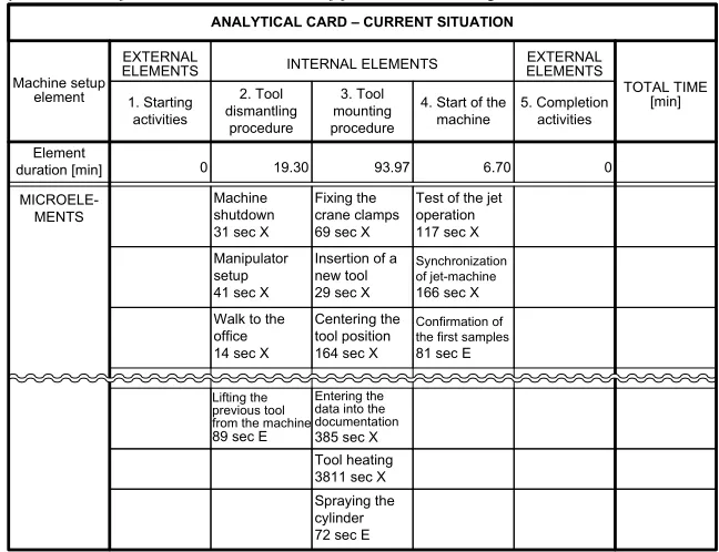
At the beginning of the session, the moderator projected the analytical card for entering the current situation onto the panel. By affixing stickers to the panel (in agreement with other team members) the current situation of jet-machine setup was obtained (Table 3).
Phase 1: Separation of internal and external setup microelements
Table 3. Analytical card of the current situation of jet-machine setup
ANALYTICAL CARD – CURRENT SITUATION
Machine setup element
EXTERNAL
ELEMENTS INTERNAL ELEMENTS EXTERNAL ELEMENTS
TOTAL TIME [min] Element duration [min] 1. Starting activities 2. Tool dismantling procedure 3. Tool mounting procedure
4. Start of the machine
5. Completion activities
0 19.30 93.97 6.70 0
MICROELE-MENTS
Machine shutdown 31 sec X
Fixing the crane clamps 69 sec X
Test of the jet operation 117 sec X Manipulator
setup 41 sec X
Insertion of a new tool 29 sec X
Synchronization of jet-machine
166 sec X Walk to the
office 14 sec X
Centering the tool position 164 sec X
Confirmation of the first samples
81 sec E
Lifting the previous tool from the machine
89 sec E
Entering the data into the documentation
385 sec X Tool heating 3811 sec X Spraying the cylinder 72 sec E
Table 4. Analytical card for separation of internal and external microelements
ANALYTICAL CARD – separation of elements
Machine setup element
EXTERNAL
ELEMENTS INTERNAL ELEMENTS ELEMENTSEXTERNAL
TOTAL TIME [min] Element duration [min] 1. Starting activities 2. Tool dismantling procedure 3. Tool mounting procedure
4. Start of the machine
5. Completion activities
0 19.30 93.97 6.70 0 119.97
MICROELE-MENTS
Machine shutdown 31 sec X
Fixing the crane clamps 69 sec X
Test of the jet operation 117 sec X Manipulator
setup 41 sec X
Insertion of a new tool 29 sec X
Synchronization of jet-machine
166 sec X Walk to the
office 14 sec X
Centering the tool position 164 sec X
Confirmation of the first samples
81 sec E
Lifting the previous tool from the machine
89 sec E
Entering the data into the documentation
385 sec X Tool heating 3811 sec X Spraying the cylinder 72 sec E
DURATION OF INTERNAL ELEMENTS [min] DURATION OF EXTERNAL ELEMENTS [min]
0.00 12.40 24.67 6.70 0.00 43.77
M AC H IN E 1 M AC H IN E 2 M AC H INE 3 Mat erial cabi net P assage t o the hal l 1 10 t
o 40 m
Machine 1: jet-machine Machine 2: tempering device Machine 3: place of control
Fig. 8. List of paths made by the setup operator - standard machine setup procedure
The moderator marked the stickers of internal microelements with red and those of external microelements w ith green (Table 4).
The team members found that it would be possible to carry out 76.2 minutes (out of the total 119.97 minutes) of setup during the jet-machine operation—this is the duration of the external microelements of machine setup.
Phase 2: Transformation of internal microelements into external ones
The moderator moved (in agreement with team members) the green stickers (external microelements) either to column 1 (starting activities) or to column 5 (completion activities) (Table 5).
Phase 3: Improvements of internal and external microelements
After the separation of internal and external microelements of machine setup, the team made some suggestions for improvements of internal and external microelements.
The results of the creativity workshop are presented in Table 6.
Table 5. Analytical card of transformation of internal into external microelements of jet-machine setup
ANALYTICAL CARD – conversion of microelements
Machine setup element
EXTERNAL
ELEMENTS INTERNAL ELEMENTS ELEMENTSEXTERNAL
TOTAL TIME [min] Element duration [min] 1. Starting activities 2. Tool dismantling procedure 3. Tool mounting procedure
4. Start of the machine 5. Completion activities MICROELE-MENTS Machine shutdown 31 sec X
Fixing the crane clamps 69 sec X
Test of the jet operation 117 sec X Manipulator
setup 41 sec X
Insertion of a new tool 29 sec X
Synchronization of jet-machine
166 sec X
Walk to the office 14 sec X
Centering the tool position 164 sec X
Confirmation of the first samples
81 sec E
Lifting the previous tool from the machine
89 sec E
Spraying the cylinder 72 sec E
0.00 12.40 24.67 6.70 0.00 43.77
73.00 0.00 0.00 0.00 3.20 76.20
73.0 12.4 24.67 6.7 3.2 119.97
Entering the data into the documentation 385/2=192 sec X
Entering the data into the documentation 385/2=192 sec X
Tool heating 3811 sec X
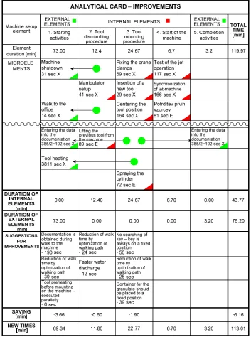
Table 6. Analytical card of improvements to internal and external microelements of jet-machine setup
The results of the first SMED workshop were:
a reduction of internal microelements of machine setup time from 119.97 minutes to 43.77 minutes (a reduction of 63.5%),
a reduction of the total machine setup time of 6.16 minutes.
The largest reduction of machine setup
time was achieved by moving the microelement "Tool heating" from being an internal element "3. Tool mounting" to an external element "1. Starting activities" with an anticipated time of 64 minutes.
operating temperature before mounting. Thus, heating in the machine is not necessary.
Fig. 9. Pre-heating station
The team calculated the time required for the return of investment in the pre-heating station:
N t C
A
t I
I
60 , (2)
where:
tI time for return of investment [weeks]
AI invested amount [€]
C cost of machine downtime per hour [€]
t saved time due to tool pre-heating [min/changeover]
N number of tool changeovers per week [changeovers/week].
The pre-heating station costs about € 9000. It is estimated that the tool is changed 12 times per week. The cost of jet-machine waiting-time is 54 €/h. The time saved due to tool pre-heating is 63.5 min/changeover. The return of investment in the pre-heating station is:
13.1 12 63.5 54
60 9000
t
weeks.
M AC
H INE
1 M
AC H
INE 2 M
AC H
INE 3
Mat
erial
cabinet Pass
age t
o
the hall
1
10 t
o 40
m
Fig. 10. List of new paths for the setup operator
The team organized a creativity workshop in order to eliminate unnecessary paths for the setup operator. The results of the creativity workshop are presented in Fig. 10.
Table 7. Operating instructions for jet-machine setup
Machine KM 800 OPERATING INSTRUCTIONS
No. MICROELEMENTS Pay attention to: Figure:
1 Read operating instructions 2 Check if the new tool is ready
:
:
:
15 Setup of new tool handle 16 Machine shutdown 17 Program loading
: :
:
42 Control of products Control dept. participates 43 Packing of personal tools
44 Packing of vacuum cleaner
: :
:
Phase 4: Standardization of microelements The team also carried out a standardization of internal and external microelements and entered the results on the form "Operating instructions for jet-machine setup" (Table 7).
The new operating instructions had to be tested, so the day after the first SMED workshop the setup operator carried out machine setup according to the new operating instructions and completed internal microelements within 39 minutes, which is an additional improvement of 4.77 minutes.
Step 7: REPEATED ANALYSIS OF MICROELEMENTS
The target setup time defined in step 2 was not achieved, so the team decided to repeat the analysis of machine setup microelements.
Before the second SMED workshop, the team leader organized a creativity workshop in order to obtain suggestions for improvements, the realization of which would additionally reduce setup time.
The creativity workshop indicated that setup time could be significantly reduced if the following improvements were made:
introduction of fast hydraulic chuck-and-center system for tool fixing,
introduction of fast hydraulic multi-joints.
3 CONCLUSION
The manufacturing management decided that the KM 800 jet-machine setup time should be reduced. They selected team members to carry out a SMED workshop with the goal of reducing the setup time. The target value was a reduction of 50%.
The team first documented the elements of the existing jet-machine setup, recorded microelement setup times, drew the path made by the setup operator, took photos of setup details and filmed the whole setup procedure with a video camera.
An analysis of setup microelements was then made, which indicated that some internal microelements could be transformed into external ones.
The team leader organized a creativity workshop, the goal of which was to make improvements to internal and external microelements. The creativity workshop yielded
two suggestions for improvements that should significantly reduce the setup time.
The SMED workshop on the reduction of jet-machine setup time will be repeated until the goal has been achieved: a setup time shorter than 10 minutes [14].
4 REFERENCES
[1] Shingo, S. (1985). A Revolution in manufacturing: The SMED system.
Productivity Press, Portland, Oregon. [2] Van Goubergen, D., Van Landeghem, H.
(2002). Rules for integrating fast changeover capabilities into new equipment design. Robotics and Computer Integrated
Manufacturing, vol. 18, p. 205-214.
[3] Mileham, A. R., Culley, S. J., Owen, G. W., McIntosh, R. I. (1999). Rapid changeover – a pre-requisite for responsive manufacture.
International Journal of Operations&
Production Management, vol. 19, no. 8, p.
785-796.
[4] Cakmakci, M. (2009). Process
improvement: performance analysis of the setup time reduction - SMED in automotive industry. Internation Journal of Advanced
Manufacturing Technology, vol. 41, p.
168-179.
[5] Sekine, K., Arai, K. (1992). KAIZEN for quick changeover – going beyond SMED.
Productivity Press, Portland, Oregon. [6] Belbin, R. M. (2003). Team roles at work.
Elsevier, Amsterdam.
[7] Menzel, F. (2009). Produktionsoptimierung
mit KVP. mi-Fachverlag, München.
[8] Steven, B. (2006). Total preventive
maintenance. McGraw Hill, New York.
[9] Starbek, M., Petrišič, J., Kušar, J. (2000). Extended ABC analysis. Strojarstvo, vol. 42, no. 3-4, p. 103-108.
[10] Fulder, T., Palčič, I., Polajnar, A., Pižmoht, P. (2005). The process of manufacturing-capability development in industrial cluster - A case study of the automotive cluster of Slovenia, Strojniški vestnik – Journal of
Mechanical Engineering, vol. 51, no. 12, p.
771-785.
Journal of Mechanical Engineering, vol. 54, no. 9, p. 607-618.
[12] INTERPLACE (2008). User's manual, Belbin Associates.
[13] Scherer, J. (2007). Kreativitätstechniken. Gabal Verlag, Offenbach.
[14] Kušar, J., Berlec, T., Duhovnik, J., Grum, J., Starbek, M. (2005). Finding and exploiting the hidden logistic potentials in a company. Strojniški vestnik – Journal of
Mechanical Engineering, vol. 51, no. 6, p.