Flow Characteristics of Bladeless Impeller Made of Open Cell
Porous Material
Gašper Benedik1,2,*, Brane Širok2, Janez Rihtaršič1, Marko Hočevar2 1 Domel d.d., Slovenia
2 University of Ljubljana, Faculty of Mechanical Engineering, Slovenia
This article describes a bladeless turbo machine impeller that transfers energy from rotor to fluid over a structure of porous material. Impeller construction is described and theoretical description of fluid flow through rotating porous material is given. Pressure drops for impellers made of different materials and with different design parameters in dependence on air volume flow rate were measured. Measurements of local air flow velocity field close to impeller circumference were performed on a stationary impeller with one component hot-wire anemometer. Air flow velocity dependence on local material structure and volume flow rate was analysed. Integral characteristics measurements for different impellers made of different materials and with different design parameters are presented. Local measurements of local radial and tangential velocities close to rotating impeller circumference are shown.
©2010 Journal of Mechanical Engineering. All rights reserved.
Keywords: bladeless impeller, turbo machine, porous open cell material, velocity field, hot-wire anemometer
0 INTRODUCTON
In a common type of centrifugal turbo machine energy is transferred from motor to fluid over impeller blades. Such machines are widely and successfully used, however, they have some limitations. Because blade design is optimised only for optimal working point, unwanted phenomena are common, such as flow separation, reverse flow, stall and surge outside optimal working point [1]. As a consequence efficiency outside of working point decreases and noise level increases [2].
This paper presents a centrifugal turbo machine in which is the energy from the rotor to the fluid is transmitted over the structure of porous open cell material and not over impeller blades, as in common turbo machinery [3] and [4]. It is expected that in this type of bladeless impeller made of open cell porous material all earlier mentioned unwanted phenomena should be absent and due to variable fluid flow streamlines this impeller should reach relatively uniform efficiency in a wide working regime. Its weakness is pressure drop which occurs during the fluid flow in porous structure and consequently reduction in efficiency that is expected to be larger in high volume flow regime because of higher relative fluid flow velocities in
porous material [4]. Consequently we expect the impeller is more suitable for use at low and medium volume flow rate working regime. We are particularly interested in flow regime up to the volume flow rate of 8 dm3/s, where the impeller of selected size will be preferably used.
This research will investigate pressure drop in dependence on air volume flow rate passing the stationary bladeless impeller. Different variants of rotating impellers will also be investigated. The influence of material choice and changes of impeller dimensions will be analysed. We focus on low volume flow rate regime, where unwanted phenomena in conventional types of impellers are present. Paper should be considered as a study aimed at confirming the operation of bladeless impeller and revealing its integral and local characteristics. Hot-wire anemometry will be used for local characteristics measurements. The research will be limited to impeller rotational frequency of 10,500 min-1. However, limited tensile strength of used porous material [5] enables rotational frequency of up to 20,000 min-1.
shaft torque and power [7]. Tesla turbo machine is interesting because of its simplicity, nearly white noise spectra and its possibility of using non-Newtonian, very viscous fluids or even abrasive two-phase flow mixtures [7]. However, due to low aerodynamic efficiency, which reaches 60% at most and drops rapidly outside the optimal working point, the device has not achieved wide industrial application [7]. Norbert [8] describes a patented device, where a disc of open cell porous material is rotated around the central axis. However, the flow direction is axial and the function of porous material is dust filtration and not fluid flow generation. There are a number of articles which investigate fluid flow through stationary metal foam. Dukhan [9] experimentally investigates pressure drop in dependence on volume flow for different materials. Boomsma [10] uses numerical simulation to investigate fluid flow through open cell foam on micro scale. Auriault [11] and Sawicki [12] theoretically describe laminar fluid flow through rotating porous media. There are no available references for experimental research done on bladeless impeller similar to the one described in this paper.
0.1 Impeller Design
The design of bladeless impeller is shown in Fig. 1. Upper and lower wall and porous structure were manufactured to the selected size. The porous material with the height of 12.5 or 8.5 mm was inserted between both walls and the structure was assembled with six rivets. Fig. 2 shows two samples of bladeless impellers. Booth walls were manufactured with a CNC milling
machine and consist of aluminium. Impeller is working on a common shaft with electric motor and rotates around the axis. Radial inducer, shown in Fig. 2b was also added for certain measurements. Impeller assembly outer radius was 62.5 mm and its height was 15 or 11 mm, depending on porous material used. 12.5 or 8.5 mm in height respectively. Each impeller was statically balanced by the removal of upper wall material.
Fig. 1. Impeller design with assembly parts [3]: (1) radial direction of fluid velocity at the exit, (2)
axial direction of fluid at the entrance, (3) impeller upper wall, (4) open cell porous material, (5) axis of rotation, (6) impeller lower
wall
0.2 Choice of Porous Material
An example of used open cell porous material is shown in Fig. 3. It consists of open cell metal foam, produced by ERG materials, made of aluminium with homogenous structure and 88% material porosity. Porosity is evaluated as:
.
empty
empty solid V
V V
(1)
Vempty represents volume without solid
material and Vsolid volume of solid material. 88%
porosity was chosen due to relatively low fluid flow resistance, low density and sufficient mechanical strength [5] and [9]. Computer tomography shows that real 3D structure differs from theoretical equilibrium models [13]. Individual sizes of pores and cells in the same material differ significantly, so we can only talk about structure's average properties. We use common expression PPI (pores per inch) which describes the average number of pores per inch [5]. In experiment 10, 20 and 40 PPI materials will be used.
Fig. 3. Magnified photo of used porous material showing pore and cell diameter [9]
1 THEORETICAL BACKGROUND
This section considers fluid flow passing through a stationary and rotating bladeless impeller, and is necessary for understanding the operation of device and understanding the later presented experimental results. Fig. 4 represents forces acting on elementary volume of fluid in rotating porous material. Dotted line represents flow trajectory and v elementary volume velocity in absolute coordinate system. Fd represents drag
force, which acts in the opposite direction of particle relative velocity. Fc is centrifugal force
and is a consequence of rotation with angular velocity ω. Fp is pressure force which is a
consequence of pressure difference in different sides of elementary volume acting on elementary volume.
Radial equilibrium theory [14] describes the passing of fluid through impeller without considering the shape of the blade, so it can be used to describe phenomena in a bladeless impeller. Basic assumption is that due to rotation,
centrifugal force Fc acts on the elementary
volume of fluid. Consequently elementary volume moves in radial direction out of impeller. The phenomena is named forced vortex present in contrast to free vortex which occurs in inlet and outlet impeller region.
Fig. 4. Forces acting on elementary volume of fluid in rotating porous material in absolute coordinate system with elementary volume of
fluid in rotating field [9]
Another approach to theoretically describe the combination of laminar and turbulent fluid flow in rotating material with high porosity present can be carried out with the upgraded Darcy equations, called also called Darcy-Forchheimer equations [15]. It can be deducted from Navier-Stokes equations [16] and [17]:
f p v v C v
K
(2)
0
v . (3)
2 2 2
2
4
2 r h
Q c h r Q k dr dp . (4)
We have assumed that pressure difference dp varies only with change of impeller radius r. The integration of impeller inner radius R1 to
impeller outer radius R2 gives pressure drop Δp:
dr h r Q c h r Q k R R p R R ) 4 2 ( , 2 1 2 2 2 2 2 1
. (5)Our goal is low pressure drop Δp and thus the use of material with a high coefficient of permeability k and low coefficient of drag c. Decrease in pressure dropΔp could be achieved by increasing the height of impeller h and inner diameter R1 or decreasing outer diameter R2. The
first part of equation is dominant at laminar flow and the second part at turbulent flow.
2 EXPERIMENT, STATIONARY IMPELLERS
The experiment consists of two parts, both carried out at the same measuring station, measurements on stationary impellers, described in this section and measurements on rotational impellers described in section 3. The experimental procedure included the calibration of measuring station and hot-wire anemometer, measurement of integral pressure drop for different stationary impellers and local measurements with hot-wire anemometer. Pressure drop measurements were performed at variable volume flow rates that were generated by an external flow generator. Measurements of local velocities were performed such that flow velocities were measured close to impeller perimeter using hot-wire anemometer. Impeller angular position was simultaneously measured with a potentiometer.
2.1 Experiment Description
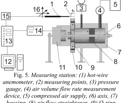
Pressure drops were measured in dependence on air volume flow rate with measuring station shown in Fig. 5. It consists of compressed air supply, volume flow rate measuring device, pressure gauge, stationary impeller and potentiometer. Hot-wire anemometer was used to measure velocity in
selected measuring points, 3 mm away from impeller perimeter. Impeller was slowly rotated with frequency 0.1 s-1, while anemometer was in fix position. Change in velocity field on account of slow rotation was corrected. Pressure differences were measured with pressure gauges. Sealing between impeller and housing was done by two O-rings, other connections were sealed with silicon kit. Air flow straightener is used to assure laminar air flow at the entrance of impeller.
Fig. 5. Measuring station: (1) hot-wire anemometer, (2) measuring points, (3) pressure
gauge, (4) air volume flow rate measurement device, (5) compressed air supply, (6) axis, (7)
housing, (8) air flow straightener, (9) O-ring sealing, (10) bladeless impeller, (11) potentiometer, (12) personal computer with A/D
converter, (13) signal conditioning unit, (14) potentiometer controller, (15) hot-wire amplifier,
(16) positioning table
Table 1 shows six different impellers which were investigated with the following parameters: inner diameter R1, outer diameter R2,
height of porous material h, PPI, average pore diameter and presence of inducer. Average pore diameter Dpore is giving the same information as
Table 1. Parameters of measured impellers
nr. R1 [mm] R2 [mm] h [mm] PPI Dpore [mm] inducer Da [/]
Impeller 1 23.75 62.5 8.5 40 0.625 no 0.316
Impeller 2 23.75 62.5 8.5 20 1.250 no 0.316
Impeller 3 23.75 62.5 8.5 10 2.500 no 0.316
Impeller 4 23.75 62.5 12.5 40 0.625 no 0.316
Impeller 5 33.75 62.5 12.5 40 0.625 yes 0.316
Impeller 6 33.75 62.5 12.5 40 0.625 no 0.316
,
2
pore D
k
Da (6)
where k represents coefficient of permeability estimated with Ergun empirical equation [18].
2.2 Integral measurements of Pressure Drop
Air flow rate is calculated with an air flow measurement device on the basis of pressure difference at the orifice k according to ISO 5167 [19]. Air volume flow rate Q was calculated:
Z z
p k Q
, (7)
where Δpz is pressure difference at the orifice and
ρz density of air calculated according to air
pressure, temperature and humidity. Integral measurement uncertainty relates to the uncertainty of pressure measurements with pressure gauges, measurement of air conditions (temperature, relative humidity and air pressure) and the uncertainty of volume flow rate measurements. Common measurement uncertainty of air pressure Δp in dependence on air flow Q is estimated with relative uncertainty of 3%.
2.3 Local Measurements of Exit Velocity Field
Because preliminary measurements have shown the dominance of radial velocity and presence of local velocity fluctuations, presence of turbulence and requirement to measure velocity field with high spatial resolution, the choice of velocity meter was important. It was found, that a five-hole probe is inadequate and that hot-wire anemometer is suitable for this type of meassurement [20]. 1D anemometer Dantec Mini CTA with sensor Dantec 55P11 was choosen. The sensor wire was 5 µm thick and 1.25 mm long. Sampling frequency was 5 kHz and sampling interval was 10 s. During the entire
sampling interval impeller was rotated slowly and measurements of velocity and angle were performed simultaneously. The temperature of anemometer wire was set to 250 °C. The distance between anemometer and porous material was 3 mm. Calibration and meassurement were carried out according to Bruun [21] and Jørgenson [22]. Measurements were performed at the distance of 3 mm from the impeller circumference. Measuring points were located along impeler height h with steps of 0.65 mm, where h = 0 mm matched wiht impeller lower wall and h = 12.5 mm matched with impeller upper wall.
Measurement uncertainty of velocity field measurement is a result of anemometer calibration, measurement of environmental conditions, limited measurement time, anemometer position and potentiometer angular position measurement, and measurement of air volume flow rate. Common measuring uncertainty velocity field measurement is estimated with relative uncertainty of 2.8% [23].
2.4 Results of Integral Pressure Drop Measurements
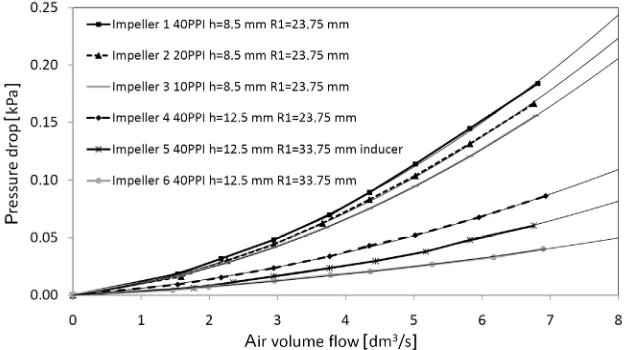
This section presents pressure drop measurements in dependence on volume flow rate for six different impellers, described in Table 1. Fig. 6 shows pressure drop in dependence on air volume flow rate for different impellers. All measurement results can be accurately approximated with second order polynomial approximation in accordance with Eq. (5). Dukhan [9] made similar conclusions doing experiments on 1D air flow through metal foam square. Pressure drop for impellers made of material with smaller pore sizes (comparing impeller 1, 2 and 3 with variable PPI, h = 8.5 mm, R1 = 23.75 mm) is slightly larger in entire volume
Fig. 6. Pressure drop in dependence on air volume flow rate for different impellers
Larger difference was expected according to measurements presented by Dukhan [9]. Smaller average pore and cell size diameter means more obstacles for fluid flow through material and larger boundary layer surface. As a consequence higher drag coefficient c and lower coefficient of permeability k appear, which reflects in higher pressure drop. With the increase of impeller height h from 8.5 to 12.5 mm (impeller 1 and 4) pressure drop is decreased by app. 50% due to the decrease of relative velocity according to Eq. (5). With the increase of impeller inner radius from 23.75 to 33.75 mm (impeller 4 and 6) pressure drop is decreased by 50% due to shorter air flow path through porous material and reduction of highest relative velocities in impeller inlet region. By comparing impeller with and without radial inducer (impeller 5 and 6) we notice higher pressure drop at volume flow rates higher that 2 dm3/s when inducer is used. Pressure drop in inducer occurs as a consequence of small inducer inlet angle (10°) and high number of blades (18) that represent an obstacle for air flow in radial direction (Fig. 2b).
2.5 Results of Local Exit Velocity Field Measurements
Radial velocity field around impeller perimeter will be presented. The measurement procedure is described in section 0. Only measurement on impeller 5 will be presented with
parameters given in Table 1. Fig. 7 shows radial exit velocity in dependence on angular position of hot-wire close to disc perimeter at different volume flow rates Q. Signal was captured from time dependent hot-wire velocity signal and simultaneously angular position was measured. Time averaging of signal was performed for the angle of 0.5°.
Radial exit velocity fluctuations shown in Fig. 7 are connected with structure of open cell porous material. Local distribution of pores and ligaments causes stochastic velocity fluctuations. Angular positions of local maxima and minima are preserved in tolerances at different air volume flow rates, which confirms connection with material structure.
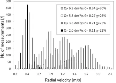
A histogram of radial velocity distribution for different volume flow rates is shown in Fig. 8. Local standard deviations of radial velocity σ increase with the increase of volume flow rate Q from 0.11 to 0.34. Meanwhile, local degree of turbulence defined with equation:
rad
v
, (8)Fig. 7. Time averaged exit radial velocities for different volume flow rate Q in dependence on angular position on stationary impeller 5
Fig. 8. Radial velocity histogram at different volume flow rates Q with given local standard
deviations σ and turbulence intensity χ on stationary impeller 5
2D radial velocity field on a segment of impeller’s outer diameter with the height of porous material at 12.5 mm and the angle of 35° is shown on Fig. 9. Surfer 8 software was used for the generation of Fig. 9b and c using kriging method. A match between the location of pores on the surface and areas with higher radial velocity is obvious (Fig. 9c). Non-matching can be assigned to several influences. Firstly, material structure under the surface which is not visible in the photo also has an influence on velocity field. Secondly, shift of high radial velocity area is caused also by a non-radial component of velocity. Thirdly, there is an influence of measurement uncertainty as described in section 0. Considering the mentioned influences there is
clear connection between local material structure and radial velocity field. As expected areas with low velocity are close to lower and upper wall of impeller (h = 0 and 12.5 mm). Results of local exit velocity field measurements have revealed flow properties and will be used in further research on rotating bladeless impeller.
Fig. 9. a) Photo of measured segment, b) Graphical presentation of 2D measured radial velocity field, c) Combination of photo and 1.5
m/s velocity contour
3 EXPERIMENT, ROTATING IMPELLERS
perimeter. Table 1 shows parameters of measured impellers.
3.1 Integral Measurements of Characteristics
Integral measurements of characteristics include the measurement of impeller aerodynamics efficiency and static pressure in dependence on air volume flow rate. The measurements were performed in Domel d.d. at the measuring device in accordance with IEC 60312 [24]. Impellers were driven by an electronically commutated electric motor with constant voltage supply. Static pressure measurements were converted to constant rotational speed 10,000 min-1. Aerodynamic efficiency ηaero is the efficiency of aerodynamic
part of turbo machine, therefore, we will simply name it impeller aerodynamics efficiency. It includes the influence of impeller used, sealing between impeller and cover, bladeless diffuser and exit openings in the cover. However, sealing between impeller and cover, bladeless diffuser and exit openings in the cover were not changed when measuring with different impellers. Aerodynamic efficiency ηaero is given as a ratio of
air power Pair and input electrical power Pel to
motor divided by motor efficiency ηm:
m el m el air aero
P
p
Q
P
P
, (9)where Q is measured air volume flow rate and Δp is the measured pressure difference. Efficiency ηm
of used electronic commutated motor was measured in the entire working regime. The motor shaft was loaded with torque from dynamometer Magtrol type 2WB43-HS. Electric power, torque and rotational frequency were measured. Torque was changed from 0 to 26 Ncm in steps of 2 Ncm. Results were presented with normalized aerodynamic efficiency, given as:
max aero
aero aeron
, (10)where ηaeromax represents maximal aerodynamic
efficiency measured with impellers (Table 1). Dimensionless air volume flow rate φ and dimensionless static pressure ψ were also used when presenting results:
, ) 2 ( 4 3 2 2 n R Q (11) . ) 2 ( 2 2 2 2 2 n R p (12)
The uncertainty of integral measurements of characteristics refers to the uncertainty of power measurement, change in motor efficiency as a consequence of heating, motor efficiency measurements, pressure measurements, measuring device calibration and measurement of environmental conditions. Common measuring uncertainty is estimated with relative uncertainty of 3.0% [4], [20] and [24].
3.2 Local Measurements of Exit Velocity Field
Local measurements of exit velocity field were performed in Laboratory for Water and Turbine Machines at the Faculty of Mechanical Engineering with calibrated 2D hot-wire anemometer Dantec Mini CTA with sensor 55P62. Sensor wires are 5 µm thick and 1.25 mm long. Sampling frequency is 50 kHz and sampling interval is 2 s. Other settings are identical to the ones, described in section 0.
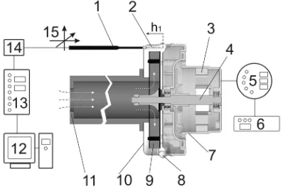
Measuring station is presented in Fig. 10. The electric motor consists of rotor, stator, housing and cover. Impeller is attached to the shaft of the motor. The orifice for the regulation of air volume flow rate and hot-wire anemometer with positioning table are also shown. Measurements were carried out along the height h1 in 20 measuring points in 1 mm steps. At h1 =
4 mm the height of a measuring point matched with the lower wall and at h1 = 16 mm the height
of measuring point matched with the upper impeller wall. Anemometer position was changed with positioning table. The air enters through the orifice, travels through the impeller and exits through the openings in the cover. Open loop regulation rotational frequency was between 8,000 and 10,500 min-1.
estimated with relative uncertainty of 3.2% [23] and [25].
Fig. 10. Schematic presentation of the measuring station for local measurements. (1) hot-wire anemometer, (2) measuring points, (3) electric motor stator, (4) electric motor rotor, (5) power
electronics, (6) constant voltage supply, (7) housing, (8) exit openings in the cover, (9) impeller, (10) cover, (11) orifice, (12) personal
computer with A/D converter, (13) signal conditioning unit, (14) hot-wire amplifier, (15)
positioning table
3.3 Results of Integral Characteristics’ Measurements
Diagram in Fig. 11 shows normalized aerodynamics efficiencies of different impellers in dependence on dimensionless air volume flow rate. We compare impellers 1, 2 and 3 with same geometric parameters, but made of porous materials with different average pore diameter. Impeller 1 with 40 PPI and h = 8.5 mm at volume flow rate 0.06 achieves approximately 6% higher normalized efficiency than impellers 2 and 3 with 20 and 10 PPI and the same height h. The difference between impellers with 20 and 10 PPI at h = 8.5 mm is small and lies within measurement uncertainty. At volume flow rate of 0.023 we notice that impeller 3 with 10 PPI has the best efficiency.
We focus on the height h of impeller (Impeller 1 and 4). We notice better aerodynamic efficiency of impeller 4 with h = 12.5 mm for flow rates 0.005 and more. Difference increases with the increase of air volume flow rate, at air volume flow rate 0.025 the difference is 30%.
If we compare impellers with different inner radius R1 (impeller 4 with R1 = 23.75 mm
and impeller 6 with R1 = 33.75 mm) we notice
better aerodynamic efficiency of impeller 4 for volume flow rate of up to 0.021 and worse aerodynamic efficiency for volume flow rates of 0.022 and more.
When comparing impellers with and without an inducer (Impeller 5 and 6), we can observe that inducer significantly improves aerodynamic efficiency in the entire working region. At volume flow rate 0.025 inducer improves aerodynamic efficiency by 30%.
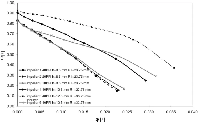
Dimensionless pressure differences of different impellers in dependence on the dimensionless air volume flow rate are presented in Fig. 12. We compare impellers 1, 2 and 3 with same geometric parameters, but made of porous material with different average pore diameters. Static pressures turn out to be the same (within the measurement uncertainty) for volume flow rate of up to 0.19. At higher volume flow rates impeller 3 made of 10 PPI material generates slightly higher static pressure.
We focus on height h of impeller (impeller 1 and 4). We notice higher static pressure when impeller 4 with higher height h is used. The difference increases from 3% at zero volume flow rate to 22% at volume flow rate of 0.026.
Comparing impellers with different inner radii (impeller 4 with 23.75 mm and impeller 6 with 33.75 mm) we notice higher static pressure of impeller 4 for volume flow rate of up to 0.018 and lower at volume flow rates exceeding 0.018. Comparing impellers with and without an inducer (impeller 5 and 6), we see that inducer significantly increases static pressure in the entire working regime.
For the explanation of results we can compare Figs. 11 and 12 with Fig. 6. By comparing impeller 1, 2 and 3 we can explain better integral characteristic of impeller 3 at higher volume flow rates by slightly lower pressure drop if material with larger average pore diameter is used (10 PPI). Explanation of better integral characteristics of impeller with higher height (impeller 1 and 4) and impeller with larger inner radius (impeller 4 with 23.75 mm and impeller 6 with 33.75 mm) is also due to lower pressure drop as seen in Fig. 6.
Fig. 11. Diagram of normalized efficiency of impellers in dependence on dimensionless air volume flow rate
Fig. 12. Dimensionless static pressures of different impellers in dependence on air dimensionless volume flow rate
Integral characteristics of bladeless impellers could be improved. The most important disadvantage of porous impeller is flow condition at the entrance of airflow into the impeller. The geometry of porous structure does not allow efficient air flow into porous impeller. This disadvantage could be to large extent eliminated by using an inducer. This can be confirmed by the
The second possibility for optimisation is to change the geometry in flow tract. As shown in Figs. 6 and 12 pressure drop in porous material is responsible for changes in static pressure characteristics. As pressure drop is high in regions where air flow velocity through porous material is high; that is in the entrance part of impeller, we propose an increase of impeller height h in this particular region.
3.4 Results of Local Measurements of Exit Velocity Field
Local velocity measurement results of radial and axial velocity field will be presented in the following section. Measurements were performed according to the experimental procedure with impeller 5, presented in section 0.
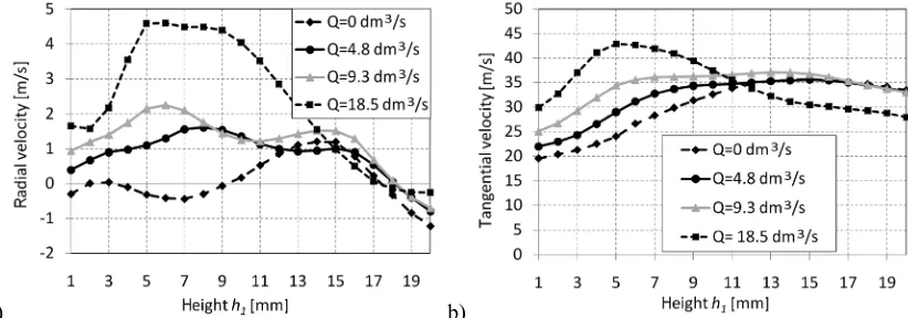
Fig. 13 shows exit velocity field profiles close to impeller perimeter in dependence on height h1. Fig. 13a presents radial and b tangential
velocity field profile. Both radial and tangential velocities decrease as air volume flow rate decreases. In Fig. 13a at zero flow rate we notice a phenomena of recirculation (Q = 0 dm3/s). Air exits the upper part of impeller (9 mm < h1 < 18
mm) and enters the lower part of impeller (4 mm < h1 < 9 mm). Negative radial flow velocity at
height h1 of more than 17 mm at all measured
volume flow rates shows air circulation between the impeller upper plate and cover. In order to track fluid flow trajectories, not only at exit from impeller, but also through metal foam, a visualisation method should be considered.
Method similar to the one used by Rihtaršič [26] or Eberlinc [27] should be applied.
4 CONCLUSIONS
This paper presents a bladeless impeller, in which the energy is transferred over a structure of porous material. We provide a theoretical background of fluid flow passing through rotating and stationary bladeless impeller. Models of different impellers are described and manufactured. The analysis of fluid flow through stationary impellers has shown that in order to decrease pressure drop impeller inlet diameter and impeller height should be increased. The choice of material average pore diameter also has an influence on pressure drop, but its influence is limited. Radial velocity field close to impeller perimeter was measured and velocity fluctuations have shown its connection with local material structure. Radial velocity above the location of pores was evidently higher than radial velocity above the ligaments.
Integral measurements of rotating bladeless impeller have shown static pressure and air flow generation as assumed in the theoretical part. The impeller with increased height, increased inner diameter and with radial inducer has shown the best integral characteristics. It was found that the inducer significantly improves flow conditions at the entrance of the impeller. We assume there is a possibility to improve integral characteristics of impeller by optimizing the inducer design and with variable height of impeller.
a) b)
ACKNOWLEDGEMENT
Research was funded by European social fund and Ministry of Higher Education, Science and Technology, Republic of Slovenia.
REFERENCES
[1] Lakshminarayana, B. (1996). Fluid dynamics and heat transfer of turbo machinery. Aerospace Engineering, Pennsylvania. [2] Čudina, M., Prezelj, J. (2007). Noise
generation by vacuum cleaner suction units, Part 1, Noise generating mechanisms. Applied acoustics, vol. 68, p. 491–502. [3] Širok, B., Benedik, G., Močnik, A. (2008).
Centrifugal turbo machine rotor.
P-200800232. Patent announcement,
Ljubljana. (In Slovenian)
[4] Benedik, G., Širok, B., Hočevar, M., Močnik, A. (2009). Research on bladeless impeller from porous open cell material.
Conference Kuhelj's Days, Brnik. (In
Slovenian)
[5] Liu, P.S. (2004). Tensile fracture behaviour of foamed metallic materials, Materials science and engineering, vol. 384, p. 352-354.
[6] Tesla, N. (1913). Fluid propulsion
P1061142. Patent announcement, New
York.
[7] Rice, W. (1991). Tesla turbo machinery,
International Nikola Tesla symposium,
Arizona.
[8] Norbert, M. (2000). Patent DE 19838265. Patent announcement, Kunzelsau.
[9] Dukhan, N. (2006). Correlations for the pressure drop for flow through metal foam. Exp Fluids, vol. 41, p. 665–672.
[10] Boomsma, K., Poulikakos, D., Ventikos, Y. (2003). Simulation of flow through open cell metal foam using an idealized periodic cell structure, International Journal of Heat and fluid flow, vol. 24, p. 825–834.
[11] Auriault, J.L., Geindreau, C., Royer, P. (2002). Coriolis effects on filtration law in
rotating porous media. Transport in Porous Media, vol. 48: p. 315–330.
[12] Sawicki, E., Geindreau, C., Auriault, J.L. (2005). Coriolis effects during fluid flow through rotating granular porous media, Studia Geotechnica et Mechanica, vol. 27, no. 1–2, p. 143-154.
[13] Borovinšek, M., Vesenjak, M., Matela, J., Ren, Z. (2008). Computational reconstruction of scanned aluminum foams for virtual testing. Journal of the Serbian Society for Computational Mechanics, vol. 2, no. 2, p. 16-28.
[14] Turton., R.K. (1984). Radial equilibrium theory, Principles of turbo machinery, Springer, New York.
[15] Kramer, J., Jelc, R., Škerget, L. (2009). Modeling of turbulent flow in porous media.
Conference Kuhelj's Days, Brnik. (In
Slovenian)
[16] Jecl, R., Škerget, L., Kramer, J. (2005). Comparison between the Forcheimer and the Brinkman model for convective flow in porous cavity with boundary domain integral method. Acta hydrotech., vol. 38, p. 1-17. [17] Vafai, K., Hadim, A.H. (2000). Handbook of
porous media, Section 9: Flow and thermal convection in rotating porous media, Marcel Dekker, New York.
[18] Dukhan, N., Patel, P. (2008). Equivalent particle diameter and length scale for pressure drop in porous metals, Experimental and thermal fluid science, vol. 32, p. 1059-1067.
[19] EN ISO 5167-1 (2003). Measurement of fluid flow by means of pressure differential devices inserted in circular cross-section conduits running full.
[20] Eberlinc, M., Širok, B., Hočevar, M., Dular, M. (2009). Numerical and experimental investigation of axial fan with trailing edge self-induced blowing. Forsch Ingenieurwes, Springer-Verlag, vol. 73, p. 129–138. [21] Bruun, H.H. (1995). Hot-wire anemometry -
Principles and signal analysis, Oxford
[22] Jørgensen, F.E. (2005). How to measure turbulence with hot-wire anemometers, A practical guide, Dantec Dynamics.
[23] Eberlinc, M., Širok, B., Hočevar, M. (2009). Experimental investigation of the interaction of two flows on the axial fan hollow blades by flow visualization and hot-wire anemometry. Experimental thermal and fluid science, vol. 33, p. 929–937.
[24] IEC 60312:1998+A1:2000+A2:2004 (2005). Vacuum cleaners for household use – Methods of measuring performance, Vilnius. [25] Benedik, G., Markič, I., Močnik, A., Širok,
B., Hočevar, M., Rihtaršič, J. (2007).
Optimisation of rotational separator for water vacuum cleaners. Ventil, vol. 13 no. 4, p. 250-256. (In Slovenian)
[26] Rihtaršič, J., Šubelj, M., Hočevar, M., Duhovnik, J. (2008). Flow analysis through the centrifugal impeller of a vacuum cleaner unit. Strojniški vestnik - Journal of mechanical engineering, vol. 54, no. 2, p. 81-93.
![Fig. 1. (1) radial direction of fluid velocity at the exit, (2) material, (5) axis of rotation, (6) impeller lower Impeller design with assembly parts [3]: axial direction of fluid at the entrance, (3) impeller upper wall, (4) open cell porous wall](https://thumb-us.123doks.com/thumbv2/123dok_us/8952711.1862079/2.539.71.473.449.649/direction-velocity-material-impeller-assembly-direction-entrance-impeller.webp)
![Fig. 4. Forces acting on elementary volume of fluid in rotating porous material in absolute coordinate system with elementary volume of fluid in rotating field [9]](https://thumb-us.123doks.com/thumbv2/123dok_us/8952711.1862079/3.539.69.252.240.372/forces-elementary-rotating-material-absolute-coordinate-elementary-rotating.webp)