JAST. Vol. 9, No. 1, pp 37-48
© Iranian Aerospace Society, Winter - Spring 2012
J
Journal ofA S T
Aerospace Science and Technology1 Introduction
The helicopter rotor wake is among the most complex ! -" # $ % "&'"& ( )& *! " + & "
Helicopter Rotor Airloads Prediction, Using CFD and Flight Test
Measurement in Hover Flight
D. Hassanzadeh
12
An implicit unsteady upwind solver including a mesh motion approach was ap-plied to simulate a helicopter including body, main rotor and tail rotor in hover ! " -#$!"#% & ' () * ) + ) $.(% / -. -. Ultimately, our calculations yielded valid solutions to the blade loading and wake
Keywords0"(). ). ( )(
1$" +%)2+.") 2)2
3. 4&+5 8
/&'"& & 5&6! : ;&<! =&> $=>% ?! " => =-&> @ /& /& B!+ C D + " C >
<E F+CDGH"C
D ' "& H ;*6 $HG/% F H / F H -CJ KL$JKL% & D M "O C " " " " PPK -<
2 Governing Equation
>$HG/%$F -H% &
2.1 Steady formulation
'-CC( ' C C C -C D C C -MC + ( C & " + ( QRUUUC! R!-: # $)%
>
@
>
@
>
@
>
@
>
@
» » » » » » ¼ º « « « « « « ¬ ª u Z U u Z U u Z U » » » » » » ¼ º « « « « « « ¬ ª u Z u Z U u Z U u Z U u Z U » » » » » » ¼ º « « « « « « ¬ ª U U U U 0 k . q j . q i . q 0 G , P q r q E P k r q w Pj r q v Pi r q u r q F , E w v u U r r r r r r r r r r r r r r r r r r r r r r r r (J RC! + -#«¬
ª
2»¼
º
2
1
E
q
rP
J
U
$<%D & "& C G& /:$)% :-$:%
2.2 Unsteady formulation
#
$%
,
<6 Helicopter Rotor Airloads Prediction, Using CFD and Flight Test Measurement in Hover Flight
$% " #
$*% G $f%! & fC fRQ Qz$% $% :?"& - G&-*!
( J L $JKL% 5! JKL J & > ' -K/F
F M "O C " " "
3 Domain Setup for Two Cases
+ " KE! {E K/F ' " +:>DK D /" & "$%E; E; B;
$ % C C -C|}D ;EB<* / CC &"& &
4 Parallel Implimentation
" -C K HP( $H P (% / & M H> J ;? B < * <* D B -);*F H<)E HG/D &
5 Computational Details for the First Case
K E! & =DKD;;) *; -#%H HR;E55-R{E)%HR;??R{E HG/'-F H " & >&D D
>
R@
r0 t?; F+CDGH"C
{ &M &$<;{<;;%D ${<;% / &? "
Rotor of Caradonna and Tung.
!"#$ %C=+8 deg and MTIP=0.877.
Figure 3. Surface Grids on Domain along the Blades Surface at %C=+8 deg and MTIP=0.877.
6 Results and Discussion of First Case
D " /B ( HG/ F %/* C D + K 6; F C / *&5 F H D " F H "
(a)
Figure 4. Sectional View of Computational Grids at X/C=0.89.
&' "$
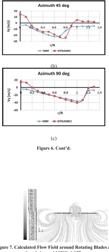
Figure 6. Induced Velocity Distribution along Blade at 45, 90 and 180 deg Azimuth Angle.
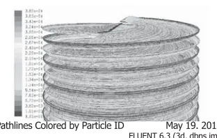
Pathlines Colored by Particle ID May 19. 2010
? Helicopter Rotor Airloads Prediction, Using CFD and Flight Test Measurement in Hover Flight
$%
$
$
$ %%%
$%
D /*$% C D $ -% ?BC ?B / " 6; /EC F H (
?B C
/ -" E! HG/ F H F H $ % H ;??;E55$/6&;%F H & -( /"&-"( Figure 6. Cont’d.
Figure 7. Calculated Flow Field around Rotating Blades at %C=+8 deg and MTIP=0.877.
?) F+CDGH"C
*- #:; Mtip<>??%C=+8 deg.
?< Helicopter Rotor Airloads Prediction, Using CFD and Flight Test Measurement in Hover Flight
D -" -K H & 6!/ :");!D-/6&; =-&> : =&> -
D
7 Computational Details for Second Case K '" " HG/F H / /
-= )
H ;*6
G B)? ! ;E<E) !
&E J *);;! H <;;H
7.1 Flight Test Measurements
P " )! / = - " ( ( " )! L / &) $ & % $;5G% / D" B+C - ) / " M ( "
KJ
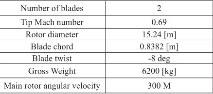
Table 1. Geometrical Information with Tip Mach number.
?? F+CDGH"C
-C "< ;;
$%
$%
7.2 CFD Simulations
/K/F$ -% KPO C C C
(C D < -> M/ /?&* ' "
HG/ H '" D ;; C / " @
/5&6 HG/ ( & : -Figure 12. Fourier Transform of Flapping and Feathering
Motion Obtained from Flight Test during 100 Rotor Revolutions
Figure 13. Blade (a) Flapping and (b) Feathering angles varia-tions for 100 rotor revoluvaria-tions.
Figure 14. Geometry of Main Rotor Blades
?B Helicopter Rotor Airloads Prediction, Using CFD and Flight Test Measurement in Hover Flight
)))<! " )?! ~ & &)B! " / K/F
D B
/ );&) F H -&& &
Fig. 16 Sectional grid points with boundary layer viscous grids.
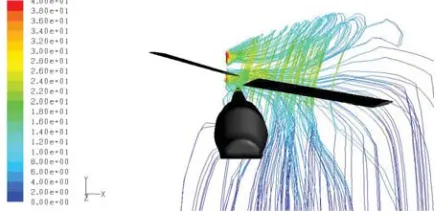
Figure 17. Pathlines Colored by Velocity Magnitude (m/s) Obtained by MRF.
Figure 18. Contours of Velocity Magnitude (m/s) Obtained by MRF- Side View.
Figure 19. Contours of Velocity Magnitude Obtained by MRF- Top View (m/s).
Figure 20. Main Rotor Streamlines Colored by Velocity Magni-tude (m/s) – Dynamic Mesh Approach.
?* F+CDGH"C
)
B D*);;;$=% <;;$=%D
H$=%
J F
$ %
>
(
> G
HG/
F
mesh
HG/
F
mesh
;E BEEB; *;)< BEB); *)B<B *B;; B *<;E* *?5B* *)6*< *B5E? *B;;
< *<<65 *?6BB *<;;5 **B< *B;;
-< & F
H(&/$=%
J F
$ %
>
( >
H
HG/
F
mesh HG/
F
mesh
;E <5;B5 <6)B) <*E)? <6E5 ?;B*)
B ?);6 ?BB; ?66< ?<*B ?;B*)
< ?)<)E ?6;; ?))<5 ?5<< ?;B*)
> =
8 Structural Modeling
D "& " D ( / )<
" F H D/- ( @ & Table 2. Main Rotor Blades Thrust comparison.
Table 3. Main Rotor In-plane Force Comparison.
Figure 22. Main Rotor Mast Twisting Moment during 50 Rotor Revolutions (Flight Test) [21].
?5 Helicopter Rotor Airloads Prediction, Using CFD and Flight Test Measurement in Hover Flight
& DM D ~ F H M F
9 Conclusion
D C"& G F-CJ KL$JKL% & GD=> &" KPO + K/F : =&> -> M O " K/F -K>F$K >F %
10 Acknowledgment
+:>D
11 References
} ?6& ?5*);;
) +DK| & }+2++9 )* =B*)&*)<
< / // G L >|K & }??D/ D +>FK*;E 6EE
? HL| &- }KKDF&G&EB&;?&GO-6EB
B F L |D } 9+: )$655
* LD |D O>D D H G F L-}H/KDO>DDHGFLG&5&)? 65
5 K/FDK|/-& } E : G D&P/P)5D6E) E :D > >P |+
} ? / D + > / H6EB
6 DGF|: "}D(DD? D D K > F KD6E*
; >=L:G>H |= " "} =D>DKP&<;))$6E6%<B&<5?
> JG F ~ > HK |/" &D =&> } =D>D H& ;)E*)
?E F+CDGH"C
+//}2 9 ( ; . 2 6 BB B&)5);;*
< DK|K>O / ( + G >}2 9(; . -26 ?6<&6?6$);;<%
? ++|D K/F PD+>)D >}KK ~&<66BD +> *B6&**5
B } <5 ?6&?5*);;
* /LO:= *<)* O J / (L-=+;<5**O>D);;*
5 P F L K |J K L ( D /
K H J}+2++ 9
5=;656;<;;<5
E K/K|: }O>-DD GDFK~HG&E&D&)<
6 +~|OH =&>K// +G+}9+:<-);;)
); +C F H"C D H >D>>|P<F "}$);;&% ) |K
}+:>D
)) LD| } 9 + : < 65) 5=?)B
)< L GH H > |D }=D>DKG&)<;B65<
)? J P |L GJ -}+2++965?