GUIDELINE
Paediatric multi-detector row chest CT:
what you really need to know
Carolyn Young&Cheng Xie&Catherine M. Owens
Received: 19 October 2011 / Revised: 9 January 2012 / Accepted: 24 January 2012 / Published online: 27 March 2012 #European Society of Radiology 2012
Abstract
Background The emergence of multi-detector row CT (MDCT) has established and extended the role of CT especially in paediatric chest imaging. This has altered the way in which data is acquired and is perceived as the 'gold standard' in the detection of certain chest pathologies. The range of available post-processing tools provide alternative ways in which CT images can be manipulated for review and interpretation in order to enhance diagnostic accuracy.
Methodology Paediatric imaging technique/protocol togeth-er with radiation dose reduction is discussed in detail. The use of different post-processing tools to best demonstrate the wide range of important congenital anomalies and thoracic pathologies is outlined and presented pictorially.
Conclusion MDCT with its isotropic resolution and fast imaging acquisition times reduces the need for invasive diagnostic investigations. However, users must be vigilant in their imaging techniques to minimise radiation burden, whilst maintaining good image quality.
Main Messages
• CT examinations should be clinically justified by the referring clinician and radiologist.
• MDCT is invaluable for evaluating the central airway, mediastinal structures and lung parenchyma.
•MDCT is more sensitive than plain radiographs in detec-tion of structural changes within the lungs.
Keywords Paediatric chest CT . MDCT . Congenital chest anomalies . Obstacles
Introduction
A variety of diagnostic imaging modalities exist to demon-strate clinical anatomical abnormalities within the thorax, and the plain chest radiograph with its low radiation burden is the first-line imaging tool of choice. In selected cases, this can be supplemented by other non-ionising radiation imaging techni-ques, such as ultrasound and magnetic resonance (MR) imag-ing. However, the use of multi-detector computed tomography (MDCT) using a low radiation dose protocol for optimal paediatric chest imaging is currently considered the most valuable diagnostic tool available to accurately evaluate the central airway, cardiovascular and mediastinal abnor-malities [1–5], and the lung parenchyma. MDCT is partic-ularly useful as all of the latter information can be acquired with a single volumetric data set acquisition. MDCT is more sensitive than plain radiographs in the detection of structural changes within the lungs, e.g. large and small airways disease and lung parenchymal consolidation [6]. Using thin-slice collimation acquisition with inherent iso-tropic resolution, the image data can be manipulated and reformatted to display two- and three-dimensional (3D) images with the same spatial resolution as the axial images [7,8], thus enhancing diagnostic accuracy and providing data that can thence be used with confidence in pre-surgical plan-ning and patient management. Other advantages of MDCT include wider coverage together with faster tube rotation speeds which has reduced overall imaging time, leading to a decrease in sedation needs for younger children; improved image quality due to reduction in motion and respiratory artefacts; and high-quality depiction of small vessels due to improved contrast enhancement as a result of higher contrast
C. Young (*)
:
C. M. Owens Cardio-thoracic Unit,Great Ormond Street Hospital for Children NHS Trust, London WC1N, 3JH, UK
e-mail: carolyn.young16@yahoo.co.uk
C. Xie
College of Medical and Dental Sciences, University of Birmingham,
Edgbaston,
concentration over a shorter time period. Taking all of this into consideration, imaging with MDCT is a relatively non-invasive procedure compared to conventional angiography, but it also carries a higher radiation burden. This paper addresses these issues and also demonstrates various clinical applications of multi-detector chest CT in children.
Imaging guidelines
Radiation dose consideration
The use of ionising radiation is always of concern in paediatric CT imaging, and a careful risk benefit analysis should be done before performing CT. To minimise radiation dose and con-comitant potential risk to children, requests for CT examination should always be clinically justified by the referring clinician and radiologist thence optimised to be‘fit for purpose’.
A dedicated body–weight or body size–based imaging protocol should be developed in conjunction with manufac-turers’recommendations. A list of paediatric chest CT proto-cols (Tables1,2and3) is provided as a guideline. However, it remains the responsibility of the radiologist to further optimise scanning parameters and tailor the CT protocol to each patient’s needs. The use of 120 kVp is no longer advocated in paediatric chest imaging and should be reduced to 80 or 100 kVp [9] without detriment to image quality due to the high inherent contrast of the lung parenchyma especially when the breath is held at full inspiration. Likewise, tube current can also be re-duced but with a resultant increase in image noise [10]. The degree of tube current reduction is therefore dependent on the level of image noise that is deemed acceptable by the reporting radiologist without degradation to the spatial resolution, thus ensuring the CT images can be accurately interpreted and a diagnosis made. A constant image noise level can be maintained to follow the patient’s anatomy by employing automatic tube current modulation (ATCM) [10]. However, the tube current will increase especially over the shoulder and at the lung base/ diaphragm regions, therefore it is essential to limit coverage to the area of interest. Use of ATCM is debatable in smaller
children as they are more rounded in body shape making the use of angular tube current modulation ineffective.
More recent developments in radiation dose reduction strategies by the system manufacturers include the use of (1) filters that are automatically deployed in spiral acquisition during the compulsory‘run-up’and‘run-down’period as a means of reducing the over-ranging effect that is inherent in MDCT; (2) adaptive statistical iterative reconstruction to re-duce image noise thus allowing the reduction of imaging parameters used; (3) radiation exposure modulation over sen-sitive organs, which reduces tube output when the x-ray tube is in the AP position over the breast and thyroid region without the need to employ bismuth shielding.
Patient preparation
From our experience, children over 3 years of age are usually compliant for their procedure provided they are properly prepared through play therapy beforehand, using a mock-up toy of the scanner to take the child and their parents through the scanning process. It is also a good opportunity to assess the child’s ability to respond to breath-holding instructions, oth-erwise gentle respiration is encouraged. It is our practice to sedate children under 15 kg in weight with general anaesthesia reserved for the non-compliant patients. Our nurse-led seda-tion team will administer a short and light-acting sedative of chloral hydrate at a dose of 50 mg/kg. The use of a more quick-acting sedative of propofol administered by an anaes-thesiologist has been reported with low incidence of adverse events [11,12]. The use of ketamine and midazolam has also been reported as safe and effective [13].
Children should always have their intravenous access for contrast enhancement sited prior to arrival in the
Table 1 Guideline of imaging protocol for routine spiral chest CT
kV Ref mAs CTDIvol Rotation
time (s) Collimation Pitch
<9 kg 80 60 0.88 0.5 64×0.6 1
10–15 kg 100 30 1.00 0.5 64×0.6 1
16–25 kg 100 38 1.26 0.5 64×0.6 1
26–35 kg 100 42 1.40 0.5 64×0.6 1
36–45 kg 100 48 1.60 0.5 64×0.6 1
Table 2 Guideline of imaging protocol for sequential chest HRCT
kV Ref mAs CTDIvol Rotation time (s) collimation
<15 kg 100 25 0.14 0.5 2×1.0
16–25 kg 100 30 0.18 0.5 2×1.0
26–35 kg 100 35 0.21 0.5 2×1.0
36–45 kg 100 42 0.25 0.5 2×1.0
Table 3 Guideline of imaging protocol for CT angiography
kV Ref mAs CTDIvol Rotation
time (s) Collimation Pitch
<15 kg 80 60 0.88 0.5 64×0.6 1
16–25 kg 100 30 1.00 0.5 64×0.6 1
26–35 kg 100 38 1.26 0.5 64×0.6 1
radiology department in order to help disassociate the CT department from the trauma of having the cannula sited [2].
Imaging protocols
Volumetric data acquisition protocol
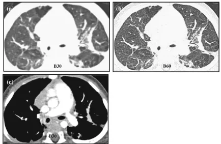
Volumetric data acquisition protocol involves a post-contrast spiral acquisition of the entire lung volume at end-inspiration. Using a low dose protocol and thin slice (0.6 mm) collimation, images are reconstructed with overlapping or contiguous sli-ces on soft tissue and high spatial resolution (bony) algorithm for optimal mediastinal and lung parenchymal display respec-tively [1,2,14,15] (Fig.1). Where patients are investigated for known or suspected airway disease or where areas of decreased attenuation are seen on the inspiratory images, three evenly spaced end-expiratory slices (at the apices, carina and lung bases) are taken to establish the presence of air trapping. Patients unable to breath-hold are placed in the decubitus position [16–18], with two spaced slices taken in both right and left decubitus positions. The dependent lung behaves in apparent expiration, whilst the non-dependent lung is in inspiration.
Three end-expiratory slices are used in order to sample the lungs and hence to limit overall radiation burden. However, studies have shown advantages to volumetric end-expiratory acquisition, with increased accuracy in quantitative assessment of the lung, in air-trapping detect-ability [19], and in determining the presence of tracheo-bronchomalacia [20]. In an attempt to minimise dose, Loeve et al. [6] came to the conclusion that the use of end-expiratory acquisition alone is sufficient to monitor the earliest changes in small airways disease in patients with cystic fibrosis.
High resolution CT
High resolution CT (HRCT), a contrast enhanced, non-contiguous sequence, limited imaging protocol, is reserved mainly for monitoring or follow-up studies in children with established diffuse large airways or interstitial lung disease. Images are acquired at end-inspiration, sampling 1 mm slices of lung with a 10–20 mm inter-slice gap. The data are recon-structed on a high spatial resolution (bony) algorithm for opti-mal lung parenchyopti-mal display. End-expiration images are acquired in a similar fashion but often only three sample slices are used.
B60 B30
(b)
(a)
B30
(c)
Fig. 1 Altering the reconstruction algorithm from soft tissue (B30) to a bony filter (B60) increases the edge enhancement between tissue interfaces, resulting in increase in image sharpness, as demonstrated in
bwhen compared toa, when viewed at the same parameter of W1200,
The radiation burden is significantly lower than for volu-metric acquisition, but HRCT has reduced sensitivity in detecting abnormalities, particularly with increasing inter-slice gap thickness [19,21].
Respiratory motion artefacts and the degree of lung infla-tion affect image quality and diagnostic accuracy. This is a major concern when imaging children who require sedation, and those too young to understand breath-hold instructions. In such cases, imaging is carried out during free breathing, which closely resembles inspiration images rather than expiration images. However, suboptimal inspiration causes an increase in lung attenuation masquerading as diffuse ground-glass infiltration [22]. In order to ensure optimal image quality acquired at total lung capacity, the use of controlled ventilation is an option in the sedated child [23]. In older children, motion-free inspiration and expiration images can be achieved by using a spirometer to monitor ventilation [24], but extra resources and an additional 20-min preparation time limit this technique for routine use. However, in comparative studies between non-contiguous HRCT and volumetric acquisition, authors have shown increased motion artefacts in non-contiguous HRCT compared to spiral/volume acquisition [25,26].
Contrast medium
Good quality contrast enhancement is essential for vis-ualising mediastinal structures in children due to lack of body fat. Contrast enhancement allows better assessment of nodes, vascular structures and branching pattern for differentiating between vessels and nodules. A low os-molar, non-iodinated contrast agent between 280 and 320 mg/l concentration is preferred. Wherever possible, this should be delivered via a dual-headed pressure injector (flow rate of 1.5–2 ml/s, maximum pressure of 100 PSI) into a (minimum) 22-gauge venflon sited in the upper arm. The contrast volume used is determined empirically according to the patient’s weight, 1.5–2 ml/kg. This is followed by a 10 ml bolus of saline solution to minimise perivenous artefacts often seen in the superior vena cava in thorax CT examination. It is also possible to administer contrast using a pressure injector through a central venous catheter (6 Fr double lumen Hickman catheter) with a 1.5 ml/s flow rate. It is our practice to use manual hand injection in neonates with a 24-gauge venflon.
Post contrast scan delay
The scan initiation time post injection differs with dif-ferent imaging protocols. If contrast is delivered via a
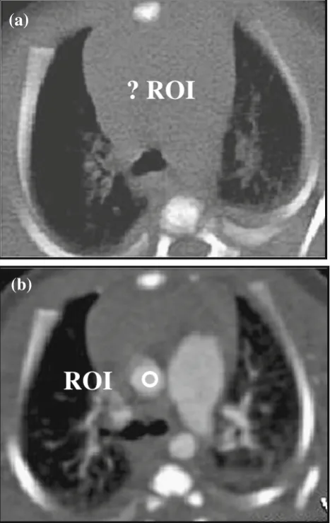
pressure injector, either a fixed scan delay of 20–30 sec is found to provide good anatomical enhancement or the scan delay can be timed to correspond to the end of the contrast and saline delivery. For hand injection, the scan starts at the end of the injection. In angiographic stud-ies, a visual bolus tracking method is used in younger children, whereby the scan is initiated by the operator when contrast is seen in the pre-determined target area on the low dose monitoring slices, with the scan region of interest (ROI) placed outside the patient to disable the automated trigger. This is due to difficulty in dis-cerning where to place the ROI on the image, as chil-dren have relatively little fat between thoracic structures
ROI
? ROI
(a)
(b)
hence a very bland mediastinum (Fig.2). An automated bolus tracking method can be used in older children. The ROI is placed at different sites to ensure maximum enhancement of the anatomical structure in question, namely the ascending aorta for aortic enhancement, the main pulmonary artery for delineating the pulmonary arteries, and the left atrium for demonstrating the pul-monary veins. The scan is triggered automatically when the contrast in these vessels reaches +100 Hounsfield units (HU).
Image display and post processing
Axial CT images contain all the necessary information for diagnostic purposes. However, complex cases can benefit with further data processing to help enhance
interpretation of the findings and improve anatomical depiction of any abnormalities seen. Various post-processing tools that are readily available on the report-ing workstation are described in this section.
Multi-planar reconstruction
Multi-planar reconstruction (MPR) is the most basic and most widely used processing tool. It allows the operator to manip-ulate and view axial images in multiple planes (coronal, sagittal or any arbitrary angulated plane) or along the axis of a structure of interest. The image quality or signal-to-noise ratio can be improved by increasing the MPR slice thickness, which is particularly useful when data are acquired with low radiation dose protocols. The disadvantage of the MPR technique is that it remains a 2-D image with no depth perception.
(iv)
)
i
i
i
(
(i)
(ii)
a
b
Fig. 3 a,bDifferent rendering software highlights different anatom-ical structures, as illustrated in these images of a 2-month-old child with congenital emphysema.aUsing the MaxIP application, the pa-renchymal vasculature is clearly seen in the coronal and axial images (i
Multi-planar volume reconstruction
Maximum intensity projection (MaxIP) is a rendering tool that extracts a volume of a contrast-enhanced anatomical structure that is then displayed as an angi-ography study. It is particularly useful in highlighting
peripheral vessels and in visualising nodules and ves-sels and also in distinguishing discrete parenchymal nodules from branching vascular structures [4] (Fig. 3a).
Minimum intensity projection (MinIP) is the opposite of MaxIP, whereby structures with the lowest attenuation
(ii)
)
i
(
(iii)
(iv)
a
b
Fig. 4 aVRT images (i–iii)demonstrate the presence of a vascular ring, and its relationship with the trachea is seen in the air bronchogram (iv). The trachea is significantly compressed by the dominant right aortic arch and the aberrant left subclavian artery passing behind the trachea and oesophagus. Scanning parameters: 80 kV, 35 eff mAs, 112 ref mAs, 0.44 CTDIvol, 6 DLP.bA surface rendered air bronchogram of the
values are extracted to demonstrate the central airway and the branching pattern of the tracheobronchial tree. This technique is particularly beneficial in the assess-ment (and quantification) of air trapping within the lungs (Fig. 3b).
3D volume rendering
3D volume rendering (VRT) is a computerised surface-rendering technique that reconstructs the volumetric ax-ial data set into a 3D display by applying a colour map to the different tissue types identified within the data set. 3D VRT imaging is widely used to demonstrate structural and vascular anatomy and in particular their spatial relationships to adjacent structures (Fig. 4a). By applying a transparent algorithm (to simulate air) to the data set the entire tracheobronchial tree can be dis-played as a 3D ‘CT bronchogram’ (Fig. 4b).
Virtual bronchoscopy
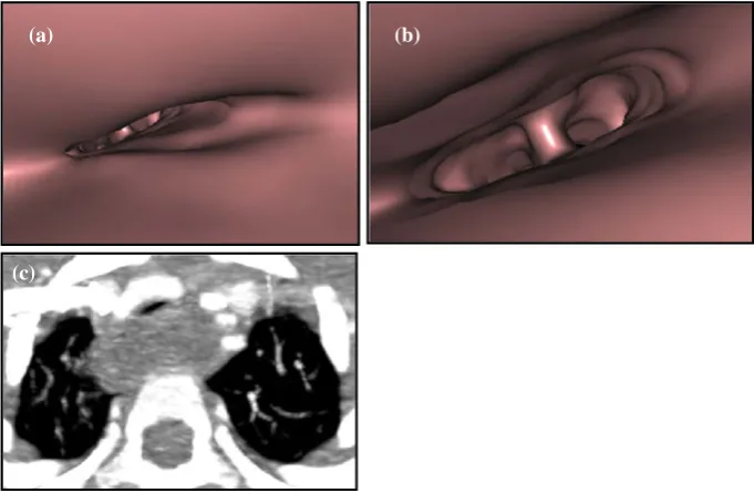
Virtual bronchoscopy (VB) is a surface-shaded display (SSD) that produces an image that mimics a broncho-scopic view of the intraluminal surface of the tracheo-bronchial tree. The operator can visualise and traverse the length of the trachea and bronchus in ‘real-time’ and ‘cross’ obstructions that an endoscope cannot tra-verse. It is useful in cases where conventional bron-choscopy is contra-indicated or in tracheal stenosis that
cannot be otherwise evaluated in three-dimensions [7] (Fig. 5).
Clinical applications
MDCT is an invaluable imaging modality in the evaluation of many paediatric thoracic abnormalities providing diag-nostic information on both lung parenchymal and mediasti-nal structures in a single CT visit. MDCT can define anomalous vasculature that is best displayed as 3D recon-structions, with clear demonstration of relationships be-tween adjacent anatomical structures. MDCT is the most sensitive modality in the detection and quantification of large and small airways disease.
Congenital lung anomalies
Congenital lobar overinflation/emphysema
Congenital lobar overinflation (CLO)/emphysema (CLE) is a progressive lobar hyperinflation anomaly due to over-distension of the alveoli and can be associated with either intrinsic/extrinsic bronchial obstruction or defective bronchial wall anatomy and structure. CLO predominantly affects the left upper and right middle lobes (Fig.6), with patients pre-senting with respiratory distress due to mass effect/compres-sion on the remaining lung and consequent mediastinal shift from the hyperinflated lobe. CLO initially appears as a soft
(b) (a)
(c)
tissue mass on plain chest radiograph from retention of foetal lung fluid. As the fluid is reabsorbed and replaced by air, lobar hyperinflation results causing a mass effect on the adjacent pulmonary lobe(s). Reduced vascularity within the over-inflated segment and contralateral mediastinal shift is evident on both chest radiograph and MDCT imaging [27].
Congenital pulmonary airway malformation
Congenital pulmonary airway malformation (CPAM) is characterised by proliferation of distal bronchioles with resultant suppression of alveolar formation. Previously known as CCAM (congenital cystic adenomatoid malfor-mation), CPAM is now the favoured descriptive term, as the lesion can be either‘solid’or‘cystic’in appearance [28,29]. There are four types of CPAM (Stocker classification): Type 1 involves macroscopic cysts greater than 2 cm, whilst type 2 presents with smaller cysts under 1 cm. Type 3 is com-posed of solid ‘adenomatoid’ tissue, and type 4 presents with very large cysts causing mass effect with lobar
expansion and mediastinal shift, as shown in Fig. 7a–g. CPAMs communicate with the tracheobronchial tree but do not have a systemic arterial supply, although hybrid lesions do exist that consist of both CPAM and pulmonary sequestration [30]. The abnormality is seen on prenatal ultrasound as a cystic or solid mixed lesion. Postnatal imaging includes chest radiograph and chest MDCT to further define and classify the lesion to assess whether surgical excision is necessary.
Pulmonary sequestration
Pulmonary sequestration presents as a non-functioning mass of pulmonary tissue that has its own aberrant systemic arterial supply, originating from the thoracic or abdominal aorta but not connected to the tracheobronchial tree. Pulmo-nary sequestration can be extra-lobar, where the focal pul-monary mass is encapsulated within its own pleura, having a systemic venous drainage and usually located in the posterior aspect of the lower thorax (Fig. 8). Alterna-tively, the sequestration can be intra-lobar, where the lesion is sited within the visceral pleura commonly found in the posterior segment of the lower lobe, often seen on the left and often associated with recurrent infections (Fig. 9). Venous drainage is conventional in intra-lobar sequestration (whilst extra-lobar sequestration has an anomalous systemic venous drainage) [27, 29]. CT angiography with 3D reconstruction aids mapping of the anomalous vasculature and distinguishes between extra-lobar and intra-lobar sequestrations [31].
Hypogenetic lung syndrome (Scimitar syndrome)
Hypogenetic lung syndrome is primarily due to abnormal right lung development that has an anomalous pulmonary venous connection. It is associated with dextrocardia and an anomalous systemic arterial supply to the right lung [27,31,
32]. Appearances on CT demonstrate a hypoplastic right lung and right pulmonary artery. The ipsilateral anomalous pulmonary vein is curvilinear in shape (like a ‘scimitar’ sword) and drains caudally in increasing diameter towards the inferior vena cava at the level of the right inferior cardiac border (Fig.10).
Tracheobronchial anomalies
Tracheomalacia
Congenital tracheomalacia is caused by collapse of the tracheobronchial wall during expiration, due to softening of the cartilaginous rings within the anterior two-thirds of the tracheobronchial wall. Acquired tracheomalacia is
(a)
(b)
caused by extrinsic compression of the trachea from the presence of vascular rings/slings. Initial diagnostic imaging
is by fluoroscopy and bronchoscopy, but MDCT ac-quired at end-expiration with MPR reconstructions
(a)
(b)
(c)
(e)
(f)
(d)
(g)
Fig. 7 Type 1 CPAM consists of a large cyst with multiple smaller cysts seen on the coronal MinIP image (a) causing mass effect with distortion to the remainder of the right lung parenchyma with mediastinal shift seen on the air bronchogram (b). Scanning parameters: 80 kV, 60 eff mAs, 60 ref mAs, 0.87 CTDIvol, 16 DLP. Type 2 CPAM with multiple cystic lesions in the right lower lobe is better defined on the coronal MinIP image (c) than on the MPR image (d). Scanning
provides additional information on the length and degree of tracheal collapse. Evaluation of the lung parenchyma
demonstrates a higher level of air trapping in patients with tracheomalacia [20].
(a)
(b)
(c)
(a)
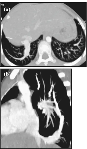
Fig. 8 Posterior VRT image (a) of an 11-month-old child demonstrates an extra-lobar sequestration with a systemic arterial supply arising from the abdominal aorta and venous drainage into the hepatic veins. Differentia-tion between normal lung parenchyma and the sequestrated lobe is seen on both the coronal air bronchogram image (b) and MaxIP image (c). Scan-ning parameters: 80 kV, 54 eff mAs, 60 ref mAs, 0.80 CTDIvol, 18 DLP
(a)
(b)
(c)
Tracheal stenosis
Congenital tracheal stenosis is a rare anomaly in which the normal membranous posterior aspect of the trachea is replaced by cartilage resulting in complete circular tracheal rings with narrowing of the tracheal lumen. The appearance on CT axial images shows an ‘O-shaped’ trachea [1] (Fig. 11). This may affect more than 50% of the trachea and involve the main bronchi and may be associated with cardiac or skeletal anomalies.
Acquired tracheal stenosis can be caused by vascular compression from the presence of a vascular ring, a pulmonary sling or a dilated oesophagus as shown in Fig. 5.
Tracheal bronchus
Tracheal bronchus is an asymptomatic congenital anom-aly often associated with other malformations such as
cardiac defects or tracheal stenosis [31]. Incidental find-ings on MDCT show a supernumerary upper bronchus (known also as a ‘pig bronchus’) arising from the right tracheal wall, superior to the carina that supplies the right upper lobe (Fig. 12). The pig bronchus can also arise from the right main bronchus as a result of an additional tracheal outgrowth during early embryonic life.
Bronchial atresia
Bronchial atresia presents with focal obliteration of a seg-mental or subsegseg-mental bronchus from mucus impaction with development of a bronchocele (Fig.13). Air trapping or hyperinflation is seen distal to the stenosis in the affected lung segment [33]. Bronchial atresia commonly affects the apicoposterior segmental bronchus of the left upper lobe, with CT being the imaging modality of choice over plain chest radiograph for visualising the obstruction and the associated segmental hypoattenuation, decreased vascularity, and possible proximal bronchocoele or broncholith [34].
(b)
(a)
Fig. 10 MaxIP images (a,b) demonstrate an anomalous curvilinear right lower pulmonary vein draining into the inferior vena cava just above the hemi-diaphragm, a classic sign of Scimitar syndrome, in a 10-year-old child. Previous metallic embolisation coils are seen on both images. Scanning parameters: 100 kV, 64 eff mAs, 150 ref mAs, 7.15 CTDIvol, 128 DLP
(b)
(c)
(a)
Bronchogenic cysts
Bronchogenic cysts are thin-walled mucoid or serous cysts caused by anomalies in lung development due to abnormal budding of the ventral embryonic foregut. The cysts are most commonly located in the mediastinum (mediastinal broncho-genic cysts) adjacent to the tracheobronchial tree but do not communicate with it and may cause extrinsic compression (Fig.14). Peripheral (pulmonary) bronchogenic cysts are usu-ally solitary and commonly seen in the lower lobes.
The cysts may present as a non-specific well-defined spherical or oval mediastinal mass on chest radiographs. They may cause distal collapse of the lung or partial obstruction with ‘ball valve effect’ that causes obstruc-tive and dramatic over-inflation of the distal lung. On MDCT, findings are of a fluid/mucoid/serous attenuation non-enhancing mass, the degree of attenuation is
dependent on the amount of proteinaceous content [3]. Post infection, there is wall enhancement after contrast administration, with air/fluid levels seen within the le-sion. CT imaging can be helpful and used to differenti-ate a bronchogenic cyst (with its characteristic features) from a more sinister mass lesion [29].
Airway disease
Bronchiectasis
Bronchiectasis is the result of irreversible bronchial dilatation and airflow obstruction with mucus impaction and bacterial colonisation. Bronchiectasis is generally classified into three types: (1) cylindrical bronchiectasis, where the dilated bronchi are relatively straight and uniform; (2) varicose bronchiectasis, in which the bronchi
(b)
(a)
(d)
(c)
Fig. 12 Incidental finding of an accessory right apical bronchus (pig bronchus) in a 3-month-old child with associated right aortic arch and an aberrant left subclavian artery (MinIP images,aandb), forming a vascular ring around the trachea, with tracheal compression (c,arrow). The pig
have a bulbous appearance with alternating areas of bronchial dilatation and constriction; (3) cystic or saccular bronchiecta-sis, where the bronchi have a ballooned appearance with associated bronchial neovascularisation and ulceration [1] (Fig.15).
CT is more sensitive in assessing bronchiectasis than the plain chest radiograph, with findings of bronchial dilatation and wall thickening that manifest as tramlines on the images (non-tapering vessels), and the ‘signet ring’ sign that is seen when the ratio of bronchial to adjacent pulmonary artery diameter is greater than one, with a ‘grape-like cluster’ of dilated large airways seen in severely affected areas. Air trapping seen on end-expiratory images is a sign of distal airflow obstruction [19].
Cystic fibrosis, a subtype of bronchiectasis, is an autosomal recessive multisystem disorder. Excessive mucus plugging of the airway together with high inci-dences of bacterial infection leads to bronchial wall inflammation that progresses to secondary bronchiecta-sis. HRCT shows bronchial wall and peribronchial in-terstitial thickening in early disease stages, whilst mucus impaction in dilated bronchioles creates centri-lobular opacities with ‘tree-in-bud’ appearances [35] (Fig. 16).
Constrictive (obliterative) bronchiolitis
Constrictive (obliterative) bronchiolitis is an irreversible obstructive lung disease caused by inflammation and fibrosis of the membranous and respiratory bronchioles, resulting in severe narrowing and bronchial obliteration. Chest radiographic findings are usually very subtle or indeed normal, despite severe respiratory symptoms and evidence of an obstructive pattern on pulmonary func-tion testing. The CT appearances include areas of hypertransradiancy due to airway obstruction by fibrous tissue causing distal air trapping and thence reflex vasoconstriction; mosaic attenuation pattern due to het-erogeneous distribution of perfusion and ground-glass changes; bronchial thickening and dilatation; and re-duced vascularity on inspiratory images and air trapping on expiratory images [35].
Congenital pulmonary alveolar proteinosis (PAP)
Congenital pulmonary alveolar proteinosis (PAP) is a disor-der unique to infancy and is due to inherited autosomal recessive deficiency of surfactant protein A, B or C and other subtypes. Chest radiographs show bilateral air-space disease, and the HRCT appearances demonstrate
ground-(a)
(b)
(c)
glass opacification from proteinaceous material filling and interlobular septal thickening giving the characteristic‘crazy paving’pattern [15] (Fig.17).
Congenital vascular anomalies
Vascular ring
Vascular ring anomalies are congenital anomalies of the aortic arch where there is resultant complete or partial encirclement of the trachea with subsequent obstruction causing respiratory distress. In certain cases the oesophagus can also be encircled within the ring. Common types of vascular ring include (1) double aortic arch, where two aortic arches arise from the ascending aorta and join together behind the trachea to form a single descending aorta (Fig. 18 ) and (2) a persistent right aortic arch, which results from involu-tion of the left aortic arch, of which there are two types.
The first is a right aortic arch with a mirror image branching pattern, in which patients are usually asymp-tomatic as the trachea is not compromised (Fig. 19a). The second type is a right aortic arch with an aberrant left subclavian artery (Fig. 19b). Patients are symptom-atic if the abnormality is associated with a large Kom-merell’s diverticulum, in which the left ligamentum arteriosum develops an aneurysm at the origin of the left subclavian artery [3, 36, 37]. MDCT angiography
(a)
(b)
(c)
Fig. 15 Three types of bronchial dilatation can be seen in patients with bronchiectasis, and their appearance on CT can be classified intoa
cylindrical,bvaricose andcsaccular shapes
(a)
(b)
can provide a comprehensive evaluation of this anomaly with 3D rendered display of the vasculature together with central airway and lung parenchyma, which may be compressed.
Pulmonary artery sling
The pulmonary artery sling is caused by an aberrant left pulmonary artery arising from the proximal right pul-monary artery. It courses to the left hemi-thorax, pass-ing between the trachea and oesophagus to the left pulmonary hilum. As a result, the left pulmonary artery forms a ‘sling’ around the distal trachea and the Fig. 16 Axial MaxIP images in
a 12-year-old child with ad-vanced cystic fibrosis show ‘tree-in-a-bud’appearances re-lated to centrilobular exudative bronchiolectasis. Scanning parameters: 100 kV, 79 eff mAs, 42 ref mAs, 2.63 CTDI-vol, 70 DLP
Fig. 17 HRCT shows ground-glass opacification with interlobular septal fluid thickening giving the‘crazy paving’appearance is illus-trated in a 1.5-year-old immuno-compromised child with cytomegalo-virus (CMV) infection. Scanning parameters: 100 kV, 41 eff mAs, 30 ref mAs, 1.38 CTDIvol, 25 DLP
(b)
(a)
(c)
Fig. 18 VRT (a) and MaxIPproximal right main bronchus, causing compression to both of these structures resulting in hyperinflation of the left lung (Fig. 20). Patients present with stridor, and apnoeic spells are common. There are two types of arterial sling [3, 30]: The first is associated with a normal carinal configuration (at the T4-T5 vertebral level) with the sling causing airway compression as describe above. The other type presents with an elon-gated trachea associated with long segment trachea ste-nosis. The bronchi branch horizontally (T-shaped) and the carina is low, usually located at T6 level. Other congenital anomalies associated with pulmonary sling include congenital heart disease, right lung agenesis or hypoplasia and horse-shoe lung.
Interruption of the pulmonary artery
Interruption of the pulmonary artery usually presents as a right-sided anomaly with the pulmonary artery blind-ending
at the hilum. The affected lung is small/hypoplastic but with normal bronchial anatomy. The arterial supply is via aorto-pulmonary collaterals with conventional venous return. In contrast, the lung on the unaffected side is usually hyperin-flated with prominent pulmonary vessels. When this condi-tion occurs on the left, it is often associated with right aortic arch, tetralogy of Fallot, patent ductus arteriosus and septal defects [31,32]. Findings are more apparent on MDCT with 3D reconstruction where termination of the pulmonary ar-tery within 1 cm from the origin of the main pulmonary artery is demonstrated together with the systemic collateral arterial supply.
Pulmonary vein stenosis
Pulmonary vein stenosis is due to uncontrolled prolifer-ation of myofibroblast-like connective tissue cells result-ing in thickenresult-ing and narrowresult-ing of the pulmonary vein (s) at the junction with the left atrium [32, 36, 37]
(ii)
(i)
a
b
Fig. 19 aPosterior oblique(Fig. 21). This anomaly commonly occurs with others (congenital heart disease and total anomalous pulmonary venous return).
Conclusion
MDCT with its isotropic resolution and fast imaging acquisition times has extended CT applications for use in paediatric chest imaging. MDCT remains the gold standard for imaging in certain pathologies and is espe-cially helpful when a diagnosis can be reached without the need for more invasive diagnostic investigations. However, radiation burden is of concern, and users must be vigilant in their dose reduction techniques, whilst main-taining good image quality which is‘fit for purpose’.
References
1. Sundaram B, Chughtai AR, Kazerooni EA (2010) Multi-detector high resolution computed tomography of the lungs. J Thorac Imaging 25:125–141
2. Toma P, Rizzo F, Stagnaro N, Magnano G, Granata C (2010) Multislice CT in congenital bronchopulmonary malformations in children. Radiol Med 116:133–151
3. Lee EY, Boiselle PM, Shamberger RC (2010) Multidetector CT and 3D imaging: preoperative evaluation of thoracic vascular and tracheobronchial anomalies and abnormalities in pediatric patients. J Pediatr Surg 45:811–821
4. Aziz ZA, Padley SP, Hansell DM (2004) CT techniques for imag-ing the lung: recommendations for multislice and simag-ingle slice computed tomography. Eur J Radiol 52:119–136
5. Boiselle PM, Lee KS, Ernst A (2005) Multidetector CT of the central airway. J Thorac Imaging 20:186–195
6. Loeve M, Lequin MH, de Bruijne M, Hartmann IJC, Gerbrands K, von Straten M, Hop WCJ, Tiddens HAWM (2009) Cystic fibrosis: are volumetric ultra-low-dose CT scans sufficient for monitoring related lung disease? Radiology 253(1):223– 229
(a)
(b)
Fig. 20 CT images (a,b) show severe tracheobronchial compression in a baby with biphasic stridor. An aberrant left pulmonary artery is seen arising from the right pulmonary artery (a), creating a vascular sling around the trachea as it passes posteriorly causing almost com-plete occlusion of the distal trachea (b), with marked narrowing of the left main bronchus. Scanning parameters: 80 kV, 58 eff mAs, 60 ref mAs, 0.86 CTDIvol, 14 DLP
(a)
(b)
7. Papaioannou G, Young C, Owens C (2007) Mulitdetector row CT for imaging the paediatric tracheobronchial tree. Pediatr Radiol 37 (6):515–529
8. Siegel MJ (2003) Multiplanar and 3D multi-detector row CT of thoracic vessels and airways in the pediatric population. Radiology 229:641–650
9. Kim JE, Newman B (2010) Evaluation of a radiation dose reduc-tion strategy for pediatric chest CT. AJR Am J Roentgenol 194:1188–1193
10. Paterson A, Frush DP (2007) Dose reduction in paediatric MDCT: general principles. Clin Radiol 62:507–517
11. Machata AM, Willschke H, Kabon B, Kettner SC, Marhofer P (2008) Propofol-based sedation regimen for infants and children undergoing ambulatory MRI. Br J Anaesth 101:239–243 12. Kiringoda R, Thurm AE, Hirschtritt ME, Koziol D, Wesley R,
Swedo SE, O’Grady NP, Quezado ZMN (2010) Risks of propofol sedation/anaesthesia for imaging studies in pediatric research. Arch Pediatr Adolesc Med 164:554–560
13. Migdady MI, Hayajneh WA, Abdelhadi R, Gilger MA (2011) Ketamine and midazolam for pediatric gastrointestinal endoscopy in the Arab world. World J Gastroenterol 17:3630–3635 14. Owens CM (2006) Pearls and pitfalls in HRCT in children.
Pae-diatr Respir Rev 7S:S44–S49
15. Klusmann M, Owens CM (2009) HRCT in paediatric diffuse interstitial lung disease—a review for 2009. Pediatr Radiol 39 (Suppl 3):S471–S481
16. Sibtain NA, Padley SPG (2004) HRCT in small and large airway diseases. Eur Radiol 14:L31–L43
17. Garcia-Pena P, Lucaya J (2004) HRCT in children: technique and indications. Eur Radiol 14:L13–L30
18. Lucaya J, Garcia-Pena P, Herrera L, Enriquez G, Piqueras (2000) Expiratory chest CT in children. AJR Am J Roentgenol 174:235–241 19. Nishino M, Hatabu H (2005) Volumetric expiratory HRCT
imag-ing with MSCT. J Thorac Imagimag-ing 20:176–185
20. Lee EY, Tracy DA, Bastos MA, Casey AM, Zurakowski D, Boiselle PM (2010) Expiratory volumetric MDCT evaluation of air trapping in pediatric patients with and without tracheomalacia. AJR Am J Roentgenol 194:1210–1215
21. De Jong PA, Nakano Y, Lequin MH, Tiddens HAWM (2006) Dose reduction for CT in children with cystic fibrosis: is it feasible to reduce the number of images per scan? Pediatr Radiol 36:50–53 22. Owens CM (2004) Radiology of diffuse interstitial pulmonary
disease in children. Eur Radiol 14:L2–L12
23. Long FR, Williams RS, Adler BH, Castile RG (2005) Comparison of quiet breathing and controlled ventilation in the high-resolution
CT assessment of airway disease in infants with cystic fibrosis. Pediatr Radiol 35(11):1075–1080
24. Mueller KS, Long FR, Flucke RL, Castile RG (2010) Volume-monitored chest CT: a simplified method for obtaining motion-free images near full inspiratory and end expiratory lung volumes. Pediatr Radiol 40:1663–1669
25. Studler U, Gluecker T, Bongartz G, Roth J, Steinbrich W (2005) Image quality from HRCT of the lung: comparison of axial scans and of sections reconstructed from volumetric data acquired using MDCT. AJR Am J Roentgenol 185:602–607
26. Bastos MA, Lee EY, Strauss KJ, Zurakowski D, Tracy DA, Boiselle PM (2009) Motion artifact on HRCT images of pediatric patients: comparison of volumetric and axial CT methods. AJR Am J Roent-genol 193:1414–1418
27. Berrocal T, Madrid C, Novo S, Gutierrez J, Arjonilla A, Gomez-Leon N (2004) Congenital anomalies of the tracheobronchial tree, lung, and mediastinum: embryology, radiology, and pathology. Radiographics 24:e17
28. Newman B (2006) Congenital bronchopulmonary forgut malfor-mation: concepts and controversies. Pediatr Radiol 36:773–791 29. Kocaoglu M, Frush DP, Ugurel MS, Somuncu I (2010)
Broncho-pulmonary foregut malformations presenting as mass lesion in children: spectrum of imaging findings. Diagn Interv Radiol 16:153–161
30. Biyyam DR, Chapman T, Ferguson MR, Deutsch G, Dighe MK (2010) Congenital lung abnormalities: embryologic features, pre-natal diagnosis, and postpre-natal radiologic-pathologic correlation. Radiographics 30:1721–1738
31. Lee EY, Boiselle PM, Cleveland RH (2008) Multidetector CT evaluation of congenital lung anomalies. Radiology 247(3):632– 647
32. Remy-Jardin M, Remy J, Mayo JR, Muller NL (2001) Vascular anomalies of the lung. In: CT angiography of the chest. Lippincott Williams & Wilkins, Philadelphia, pp 97–114
33. Müller NL, Fraser RS, Colman N, Pare P (2001) Radiologic diagnosis of diseases of the chest. Saunders, Philadelphia 34. Gipson MG, Cummings KW, Hurth KM (2009) Bronchial atresia.
Radiographics 29:1531–1535
35. Rossi UG, Owens CM (2005) The radiology of chronic lung disease in children. Arch Dis Child 90:601–607
36. Oguz B, Haliloglu M, Karcaaltincaba M (2007) Paediatric multi-detector CT angiography: spectrum of congenital thoracic vascular anomalies. Br J Radiol 80:376–383