© Shiraz University
Workability Study in Near- Peritectic Sn-5%Sb Lead-Free Solder Alloy Processed By
Severe Plastic Deformation
H. Vafaeenezhad, S. H. Seyedein, M. R. Aboutalebi
*and A. R. Eivani
Materials Processing Simulation Laboratory (MPS – Lab), School of materials and metallurgical engineering, Iran University of science and technology (IUST), Narmak, Tehran, Iran
Abstract: Severe Plastic Deformation (SPD) of Sn-5Sb solder alloy was carried out under different deformation conditions including the temperature range of 298, 330, 360, 400 K and die designs in the present research. An experimentally validated finite element method (FEM) is applied to propose a simulation strategy for predicting the workability in equal channel angular pressing (ECAP) of the alloy. Different parameters such as die angles (angle between the channels and the outer corner angle), pressing temperature and the die outlet channel geometry were studied using Finite Element Method (FEM) simulation. It was found that, by increasing both die and outer corner angle, the imposed strain rises and in the counter, through increasing the temperature, the portion of low-angle grain boundaries and recovery kinetics rate increased. Finally, presence of choke angle imposes compressive stress as well as causing an increase in the pressing pressure.
Keywords: Solder alloy, Finite element method, equal channel angular pressing
1. Introduction
The practical and outstanding manufacturing aspects of SPD has been widely taken into consideration due to exceptional physical and mechanical characteristics appear in produced ultrafine grained materials [1]. ECAP especially is a remarkable process among different methods of severe plastic deformation. The major benefit of the process is that the starting material can be pressed possessing relatively homogeneous and large shear strain without any significant variation in the cross- section area of the work-piece [2] and therefore, it is likely to repeat the pressing for more than one pass [3-4]. In other words, after one pass of ECAP, samples take high shear strain without any concomitant size or shape change and leading to the extraordinary grain refinement that [5] the final angularly pressed solids containing 1000 or more grains in one segment [6]. These characteristics make a distinction between this type of deformation with conventional metal-working procedures such as drawing, rolling or extrusion [7]. ECAP has been studied broadly, taking the advantage of many techniques including analytical material flow modeling, slab analysis, upper-bound, Artificial Neural Network (ANN) and FEM [8]. However, FEM is the most conventionally- applied and significant numerical technique that has been fruitfully employed to investigate the deformation progression and process design in SPD processes like ECAP.
Three-dimensional finite element analysis was used to numerically simulate deformation characteristics and damage evolution in ECAP and also to recognize the friction effect on pressing load, material flow pattern, texture and strain in-homogeneity of various alloys[9-12]. In the mentioned researches, the metal deformation was considered as plane strain in the simulation and accordingly 2D models were developed for analyzing ECAP method. In addition, FEM has been widely used to investigate the effects of different factors such as back pressure [13], material properties [14], ultrasonic treatment [15] and die geometry on variation of the deformation rate [7], texture [16] and the plastic
deformation zone in ECAP [17]. Additionally, strain hardening, billet length and plastic instability during ECAP were also considered using FEM strategies [18].
In recent decades, extensive use of lead- based materials which employed in the electronics industries and lubrication components have been always a serious case for environmental issues. This international concern gives rise to introduction and extensive application of alternative lead-free solder alloys to be employed in mentioned cases. Near-peritectic Sn-5Sb alloy with relative high melting point and good solder-substrate contact and acceptable degree of wetting angle [19] is one of the most advanced solders in microelectronics purposes like connectors in printed circuit boards (PCB) [20].
In the current research, the severe plastic deformation behavior of Sn-5Sb lead-free solder alloy during ECAP was studied using FEM models. In this regard, the effect of the channel geometry, outlet channel shape and pressing temperature was numerically studied and just beforehand, the simulation results were confirmed experimentally.
The current work is focused on the novel approach of workability improvement of the material in terms of wise design of die angles with a slight adaptation in die channel design. For this reason, in different section of manuscript some comparable ECAP process were judged against each other in terms of difference in the die angle, outer corner angle, temperature and design of outlet channel. The influence of a trifling deviation in die design is discussed considering the difference in the sign and magnitude of principle stresses distributed in the upper regions of pressed samples. In other words, the difference between existence of choke angle in outlet channel and conventional exit channel is discussed by taking the main term of damage in ductile materials which is maximum principle stress.
2. Experimental procedure
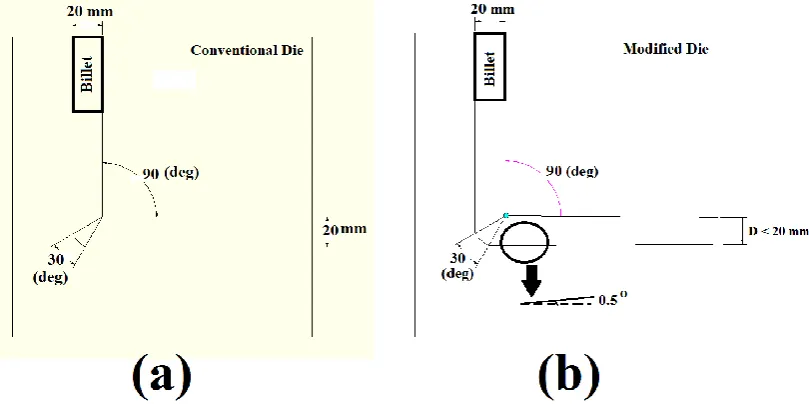
The Sn-5Sb Solder alloy was melted in a furnace with inert gas isolation and subsequently cast into a cylindrical metallic mold. The homogenization treatment was carried out by heating the samples at 170oC for 18 hours. . Two ECAP dies were designed and manufactured from hot working steel (DIN: 1.2344) with die angle and outer arc of 90O and 30O, respectively (Fig. 1). Both dies had circular cross sectional
channels with radius of 10 mm. In order to investigate the workability of alloy, one of the dies was designed to have a choked exit channel while another one had a parallel exit channel. The choke angle was designed to be 0.5 O. The pressing of material was performed with ram speed of 2mm/s. MoS
2 was used as
lubricant to reduce the friction during ECAP process.
3. Finite Element Simulation
In this work, finite element analysis of ECAP process was carried out considering different involved parameters using DEFORM-3D V6.0. The dies, billet and punch were selected according to the experimental conditions. The diameter and length of the work- piece were 20 mm and 120 mm, respectively. The plastic deformation of material at different temperatures and strain rates was defined using Zener-Hollomon equation. The total number of elements after solid mesh generation was 20,000. The automatic re-meshing utilized to establish and keep appropriate mesh quality. Friction coefficient of 0.12 and 0.25 were used for room temperature and high temperature ECAP simulation, respectively [10, 13].The boundary conditions applied to the model were as following: (i) Die get fixed by assigning zero degree of freedom to displacement and rotation in all three directions. (ii) The billet was permitted to move freely in Z direction during pressing operation in the input channel of die. (iii) As stopping criteria, the punch was set to move 120 mm in downward direction to press the material completely in the die. Finite element simulations were done according to following experimental design: various channel angle φ (90, 110, and 135), outer corner angle ψ with two values of (15 and 30) and pressing temperature of 298, 300, 360 and 400 K. All simulations were performed considering the combinations of above mentioned factors using both conventional and modified ECAP dies. Validation of FEM results was done by comparing the calculated ECAP force with experimental results for both dies. After model verification, the values of Von-Mises strain, stress and maximum applied force were recorded from simulation for all runs.
4. Results and Discussion
To validate FEM simulation of ECAP process, the magnitudes of pressing force during ECAP were measured in laboratory for both conventional and modified dies. The values of maximum pressing force predicted by simulation and those obtained from experiments are listed in Table 1 The maximum of 8% disagreement between the experimental and mathematical results confirms the validity of FEM model and makes its applicable and permitted. It is obvious that extrusion pressure is progressively decreased after reaching a maximum at around 20mm stroke. Occurrence of the increasing and then reducing trend are previously correlated to upsetting of the cylindrical sample inside the entry channel and the onset and continuation of plastic deformation.
Table 1. Comparison of simulation and experimental achievements of maximum pressing force (φ = 90O; ψ = 30O; T = 298 K)
Max. Force (KN) FEM simulation Experimental Error (%)
Conventional 44.2 48 7.9
Modified 54.3 57 4.7
During ECAP of bulk metallic materials, three general parameters control the microstructural evolution and mechanical behavior of the severely deformed billets: (I) Factors related to the experimental features of ECAP like die angle (φ) and outer arc angle (ψ). (II) Processing factors such as pressing speed, working temperature, pass number, back- pressure, pressing route and die design that can be set by operator or designer. (III) Factors with impact on grain refinement of the ECAPed microstructure including the crystallographic texture, stacking fault energy (SFE) and crystal structure.
4.1. Effect of die channel angle and die outer corner angle
The channel angle, φ, is the most considerable experimental factor because it creates the large plastic strain during each ECAP pass and forms a severely deformed microstructure. It should be noted that the most of the researches about the influence of this factor have focused on values between 90O to 150O to
lower and upper temperature of this research) while the outer corner angle is constant and the exit channel is parallel.
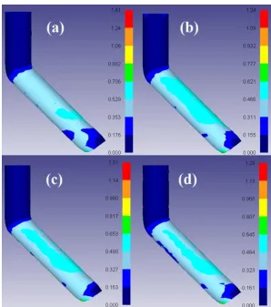
Fig. 2. Plastic strain distribution in conventional die with (a) φ = 90O (b) φ = 110O (c) φ = 135O with constant ψ = 30 O, pressed at T = 298 K.
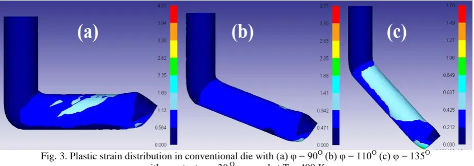
Fig. 3. Plastic strain distribution in conventional die with (a) φ = 90O (b) φ = 110O (c) φ = 135O with constant ψ = 30 O
, pressed at T = 400 K.
According to related investigation [21], it is apparent that smaller ultrafine grains with higher angles of misorientation are obtained when the material is subjected to a larger plastic strain. This is fulfilled when the pressing happen preferably in dies with lower channel angles as the die with angle of 90O
induces more plastic strain than die with angle 110O and 135O. In other words, to achieve a specific
quantity of strain, more pressing passes should be applied when the ECAP die with higher angle is used. The decrease in equivalent plastic strain by increasing the die angle is also observed in pressing process at 330 K and 360 K just like two illustrated temperatures. It is noted that the ECAP of high ductility Sn-5Sb solder alloy can be done without any problem through pressing in dies with angle of 90O or higher values.
However, in case of inflexible and low ductility materials such as tungsten, martensitic steels or composite structures, application of appropriate die angle for maximum workability may be a rational consideration. Worthy of note to see that this trend is also influential in materials deformed in die having 0.5O choked
individual ECAP pass. It can be claimed that an ECAP die can impose the maximum strain value on the billet when the die angle is 90 O. While, it is almost impossible for comparable methods like extrusion to impose such a high strain even using multiple passes.
Fig. 4. Plastic strain of deformed samples pressed at different temperatures and channel angles in conventional dies with (a) ψ = 30O (b) ψ = 15O.
Figures 6 and 7 demonstrate plastic strain distribution in conventional and modified dies with channel angle of 90O and 135O, respectively. To prove the generality and temperature- independency of ψ effect, strain
contour of samples processed by conventional die (Fig. 6) was extracted at 398 K and 400 K and for those pressed in modified die at 330 K and 360 K (Fig. 7). It can be seen, after single pass of ECAP with a constant die angle, an increase in the outer corner angle from 15O to 30O decreased effective plastic strain
level. The reason for this concurrence is upon to the existence of the dead zone which is typically appeared at the shear zone when the billet moves in the die near the intersecting zone. The formation of dead zone leads to the cease of contact between die wall and forming material.
Fig. 5. Plastic strain of deformed samples pressed at different temperatures and channel angles in modified dies with (a) ψ = 30O (b) ψ = 15O.
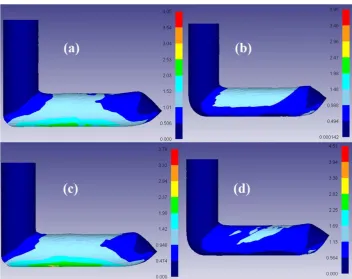
Fig. 6. Contours of strain distribution for samples angularly pressed in conventional die with φ = 90O and (a) ψ = 15O at 298 K (b) ψ = 30O
Fig. 7. Contour of strain distribution for samples angularly pressed in modified die with φ = 135O and (a) ψ = 15O at 330 K (b) ψ = 30O at 330 K (c) ψ = 15O at 360 K (d) ψ = 30O at 360 K.
Furthermore, dies with lower angles establish a considerable raise in strain in-homogeneities in the pressed billets so that makes the material flow difficult in and increases the induced strain value. As a consequence, to have a high imposed strain and more homogenous stress distribution, an ECAP die with the angle of 90 O as well as a minimum value of outer angle is required.
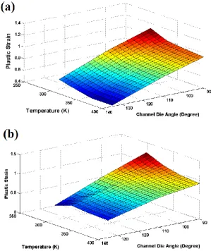
4.2. Effect of deformation temperature
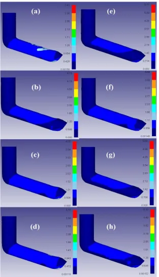
The ECAP temperature is the most important parameter among others because of its complex effect on microstructural evolution and variations of stated variables. Figs.8 indicates the strain distribution in the billet pressed at different temperatures in both ECAP dies with φ = 110O and ψ = 30 O. Because of high
stacking fault energy (SFE) of Sn-5Sb solder alloy, it can be concluded that the portion of low-angle grain boundaries is increased with increasing the temperature that consequently yields faster recovery at elevated temperatures [23]. That is to say, as temperature rises, the formation of DRV is facilitated and the critical strain for commencement of subgrain arrangement decreased as well.
Fig 8. strain distribution of ECAPed samples in the condition of φ = 110O and ψ = 30 O in conventional and modified dies at different temperatures: (a) conventional die at 298 K, (b) modified die at 298 K(c) conventional die at 330 K, (d) modified die at 330 K; (e): conventional die at 360 K; (f) modified die at 360 K; (g) conventional die at 400 K; (h) modified die at 400 K.
4.3. Effect of choke angle
Figure 9a-d show FEM contours of maximum principal stress (σ1) in conventionally ECAPed Sn-5Sb
solder alloy pressed at 298 K and 360 K with different die angles and outer corner angles. During material pressing, the existence of positive σ1 in the billet can be interpreted as emerge of succeptible zone to crack
nucleation. The maximum value of σ1, colored red in the contour plot, is detected at the top surface in the
be the main cause of crack formation, it may be perceived from FEM simulations that the top band of billet is the most dangerous region at risk of fracture.
Fig. 9. Distribution of maximum principal stress at (a) room temperature (298 K) pressed in die with φ = 90O; ψ = 15O and, (b) high temperature (360 K) in die with φ = 135O: ψ = 15O, (c) room temperature (298 K) ECAP in die
with φ = 90O; ψ = 30O and (d) high temperature (360 K) in die with φ = 135O: ψ = 30O.
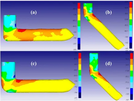
To examine the impact of outlet channel design on the prospect stress distribution and also material fracture potentiality, the exit channel configurations were considered as parallel and 0.5O choked. It is clear that the distribution of σ1, as FEM simulated maximum principle stress, for the samples pressed in
die with parallel outlet channels is not alike with the die with choked channel. It should be noted that, in all deformed severely deformed samples in different situations of die angles and pressing temperatures, the following trend was seen: In the die with choked outlet channel, σ1 is drastically decreased and
changes to a compressive mode that yields workability improvement during ECAP. When the evolution of σ1 for conventional die is considered, it is found that although σ1 for parallel die is tensile in the top band
of pressed samples, σ1 in die with choked outlet channel is compressive in more extensive regions.
choke angle in outlet die results in a slow drop of maximum principal stresses, i.e., more compressive stresses. However, it is involved with increasing strain in-homogeneity and extrusion pressure.
It should be highlighted that, this difference was seen in every process performed at different temperatures and any combination of φ and ψ = was presented in Figs. 10. It should be added that, this fact also governs the stress distribution when other affecting parameters such as die angle and deformation temperature varies.
Fig. 10. Comparison of σ1 in near- end forming step using (a) conventional die with process conditions of φ = 90 O
- ψ = 15O- T = 298 K and (b) modified die with process conditions of φ = 90O- ψ = 15O- T = 298 K along with σ1 in final forming step using (c) conventional die with process conditions of φ = 90O- ψ = 15O- T = 298 K and (d) modified die
with process conditions of φ = 90O- ψ = 15O- T = 298 K
5. Conclusion
Finite element analysis was utilized to simulate the ECAP process of Sn-5Sb lead-free solder alloy. To validate the FEM method, simulation products were judged against with the experimental quantity. The following points can be highlighted from the present investigation:
1. Maximum required extrusion forces during ECAP were numerically determined and at that time evaluated with the experimental verification. The achieved simulated FEM results are in acceptable agreement with the experimental results.
2. An increase in die angle or outer corner angle caused a decrease in the plastic strain level. On the counter side, a lower amount of strain and force has been obtained with an increase in working temperature during ECAP.
4. Performing ECAP process by a die with choked outlet channel led to a reduction in the maximum principal stresses and further stress state revolution to compressive mode. This event improves material workability during severe plastic deformation process.
6. References
[1] R.Z. Valiev and T.G. Langdon, Principles of equal-channel angular pressing as a processing tool for grain refinement, Progress in Materials Science, 51 (2006) 881-981.
[2] M. Furukawa, Z. Horita and T.G. Langdon, Factors influencing the shearing patterns in equal-channel angular pressing, Materials Science and Engineering: A, 332 (2002) 97-109.
[3] T.T. Dele-Afolabi, M.A. Azmah Hanim, M. Norkhairunnisa, H.M. Yusoff and M.T. Suraya, Investigating the effect of isothermal aging on the morphology and shear strength of Sn-5Sb solder reinforced with carbon
nanotubes, Journal of Alloys and Compounds, 649 (2015) 368-374.
[4] B.V. Patil, U. Chakkingal and T.S. Prasanna Kumar, Effect of geometric parameters on strain, strain inhomogeneity and peak pressure in equal channel angular pressing – A study based on 3D finite element
analysis, Journal of Manufacturing Processes, 17 (2015) 88-97.
[5] T.G. Langdon, M. Furukawa, M. Nemoto and Z. Horita, Using equal-channel angular pressing for refining grain size, Jom, 52 (2000) 30-33.
[6] M. Furukawa, Z. Horita, M. Nemoto and T. Langdon, Review: Processing of metals by equal-channel angular pressing, Journal of materials science, 36 (2001) 2835-2843.
[7] K. Nakashima, Z. Horita, M. Nemoto and T.G. Langdon, Influence of channel angle on the development of ultrafine grains in equal-channel angular pressing, Acta Materialia, 46 (1998) 1589-1599.
[8] C.G. Yao, B. Wang, D.Q. Yi and X.F. Ding, Artificial neural network modelling to predict hot deformation behaviour of as HIPed FGH4169 superalloy, Materials Science and Technology, 30 (2014) 1170-1176.
[9] S.C. Yoon, H.-G. Jeong, S. Lee and H.S. Kim, Analysis of plastic deformation behavior during back pressure equal channel angular pressing by the finite element method, Computational Materials Science, 77 (2013)
202-207.
[10] S. Dumoulin, H.J. Roven, J.C. Werenskiold and H.S. Valberg, Finite element modeling of equal channel angular pressing: Effect of material properties, friction and die geometry, Materials Science and Engineering: A, 410–
411 (2005) 248-251.
[11] M. Shaeri, M. Salehi, S. Seyyedein, M. Abutalebi and J. Park, Characterization of microstructure and deformation texture during equal channel Angular pressing of Al–Zn–Mg–Cu alloy, Journal of Alloys and
Compounds, 576 (2013) 350-357.
[12] N.E. Mahallawy, F.A. Shehata, M.A.E. Hameed, M.I.A.E. Aal and H.S. Kim, 3D FEM simulations for the homogeneity of plastic deformation in Al–Cu alloys during ECAP, Materials Science and Engineering: A, 527
(2010) 1404-1410.
[13] F. Djavanroodi and M. Ebrahimi, Effect of die channel angle, friction and back pressure in the equal channel angular pressing using 3D finite element simulation, Materials Science and Engineering: A, 527 (2010)
1230-1235.
[14] E. Cerri, P.P. De Marco and P. Leo, FEM and metallurgical analysis of modified 6082 aluminium alloys processed by multipass ECAP: Influence of material properties and different process settings on induced plastic
strain, Journal of Materials Processing Technology, 209 (2009) 1550-1564.
[15] F. Djavanroodi, H. Ahmadian, K. Koohkan and R. Naseri, Ultrasonic assisted-ECAP, Ultrasonics, 53 (2013) 1089-1096.
[17] G.Y. Deng, C. Lu, L.H. Su, X.H. Liu and A.K. Tieu, Modeling texture evolution during ECAP of copper single crystal by crystal plasticity FEM, Materials Science and Engineering: A, 534 (2012) 68-74.
[18] R.B. Figueiredo, I.P. Pinheiro, M.T.P. Aguilar, P.J. Modenesi and P.R. Cetlin, The finite element analysis of equal channel angular pressing (ECAP) considering the strain path dependence of the work hardening of metals,
Journal of Materials Processing Technology, 180 (2006) 30-36.
[19] E. Karaköse, M.F. Kılıçaslan and H. Çolak, Formation of novel rice-like intermetallic phases and changes in the mechanical, microstructural and electrical properties of Sn–5Sb alloys with addition Ag and Bi, Journal of
Alloys and Compounds, 655 (2016) 378-388.
[20] R. Mahmudi, A.R. Geranmayeh, M. Bakherad and M. Allami, Indentation creep study of lead-free Sn–5%Sb solder alloy, Materials Science and Engineering: A, 457 (2007) 173-179.
[21] F.J. Humphreys and M. Hatherly, Recrystallization and Related Annealing Phenomena, Elsevier Science,
(2012).
[22] F. Djavanroodi, B. Omranpour and M. Sedighi, Artificial neural network modeling of ECAP process, Materials
and Manufacturing Processes, 28 (2013) 276-281.
[23] F. Yang and M.J.C. Li, Deformation behavior of tin and some tin alloys, Journal of Materials Science: