OSTER COPY
139AUTOMATIC EQUIPMENT FOR SURFACE IRRIGATION By.
A. S. Hurnpherys Agricultural Engineer
Snake River Conservation Research Center Soil and Water Conservation Research Division
Agricultural Research Service United States Department of Agriculture
Kimberly (Twin Falls), Idaho
For
Presentation at the 1968 Annual Meeting of the
By
A. S. Humpherysli
Automatic and semi-automatic surface irrigation structures and systems are being developed to improve irrigation water management and conservation on the farm. Most mechanized structures may be classified as fully automatic or semiautomatic depending upon their
method of operation. A fully automatic system operates without attention from the operator other than periodic inspections from one irrigation to the next. The need for irrigation and often the irrigation time periods, however, are still largely determined by the irrigator who usually has to turn water into the system. The semi-automatic system uses gates and checks which are normally tripped at a preset time by a mechanical timer or electrically. In addition to determining the need for irrigation, the irrigator also manually resets the structures or moves them from one location to another, or both, prior to each irrigation. With compe. tition for available national water supplies increasing, some irrigation water users may be forced to use their water more efficiently. Auto. matic equipment provides a means of accomplishing this while at the
V Contribution from the Northwest Branch, Soil and Water Conserva-tion Research Division, Agricultural Research Service, USDA: Idaho Agticultural Experiment Station cooperating.
2
same time saving labor. At a time when reliable farm help is difficult to obtain, and wage rates are increasing, an investment in automatic
structures could be an economical alternative and may be more easily justified than in the past.
Surface flooding systems using basins, borders or contour ditches are easiest to automate since the field topography allows the entire
stream of water to be distributed over the soil surface. When furrows are used, however, the irrigation stream must be uniformly divided into many small streams directed into individual furrows. This requires furrow flow regulating devices or controls in addition to check and turn-out structures.
Review of Automatic Irrigation Equipment
Being. Developed by Various Investigators
One of the objectives of this paper is to present a brief review of the various automatic irrigation structures and devices which are available or in a state of development and which may be expected to be produced commercially. For many years attempts have been made to achieve some degree of automation in irrigation and many devices have been built with some being patented. Most however, have not been pro-duced commercially or used to a large extent. Recently, however, be-cause of critical water and labor conditions automation has attracted many individual farmers and researchers to experiment with various devices. Curtis (4)* reports the use of an automatically released can-vas dam which is built and used by some farmers in Idaho. A similar type is also being used in New Zealand (15). These are tripped by a conventional alarm clock and are used primarily with the border method
of irrigation. A border inlet gate is operated simultaneously with the release of the main canvas dam. The border inlet gate
is
usuallya
drop gate which, when released,
falls
by its own weight and stops the flow of water through an opening. It may be mounted and tripped ina
variety of. ways and has been used by farmers in this country and New . Zealand for several years GO (Z).
A system recently developed in Wyoming
(7)
uses a drop gate in the supply ditch with a cable attached to a series of small individual rotating disc gates. These are fastened to the inlet end of outlet tubes or pipes in the side of the ditch. When the drop gate is released by a mechanical timer, the cable opens the outlets in the section of•ditch immediately upstream .and allows water to flow onto the field. - Irriga.Lion proceeds up the ditch in this manner with each drop gate closing in sequence and .opening the outlet gates immediately preceding
it.
An ingenious system in California
(17)
uses a. sugar cube to trigger the termination.ofirrigation in a border. A spring loaded sensing device containing the sugar cube is located near the lower end of the • field. , When water dissolves the cube, a wire extending from the lower. end of the field to the supply ditch trips a gate on the border turnout. The turnout from the.ditch into the border is a conventional pipe. fitted with. a flap-type
gate
which closes when it is released-. When the gate closes,..: a connecting wire opens the next gate downstream which, in turn is closed at the completion of irrigation by a sensing device at the end of the border.Slow moving traveling dams which divert water continuously from
4
because of inherent problems. A modification of this system which
shows promise (5) uses a water-filled, balloon-type, drive-wheel to form the dam and to propel the machine. The combination drive-wheel and dam is formed by a water-filled rubber tube surrounding a fiberglass drum shaped to conform to the ditch.
Experimental self-propelled traveling siphons have been developed and tested in Wyoming (16) (3). These are used primarily for soils hav-ing high intake rates and with border methods of irrigation requirhav-ing large irrigation streams. A machine is supported in the ditch by pon-toon assemblies and is propelled along the ditchbank by a water turbine located at the outlet end of large siphon tubes.
A system using radio controlled inflatable pneumatic valves for con-trolling the discharge into borders was developed by liaise and Kruse (9), This was discontinued in favor of an improved system using hydrau
lically controlled butterfly gates in farm lateral turnouts (10). Double-acting water pistons open and close butterfly gates which are installed in turnout pipes into the field. Three and four-way hydraulically con-trolled pilot valves are connected into the system to control both the butterfly gates and check structures in the main ditch. A sinking float sensing device located near the lower end of the field operates a pilot valve which terminates irrigation in a particular set of borders and di• rects water into the next set. Several borders are irrigated simultane-ously with irrigation automatically moving sequentially downstream as
each group of borders is irrigated. This system requires a source of water pressure and installation of plastic hydraulic lines along the ditch bank and to the sensing device in the field. The hydraulic pressure is
A radio controlled system for border irrigation is being developed by Bowman at Montana State University (1). This system uses a mois-ture sensing device coupled with a portable radio transmitter located near the lower end of the border and a portable receiver at the upper end. A gate in the supply ditch is operated by a small battery powered DC electric motor which is actuated by a radio signal from the trans..
mitter. A similar gate in the turnout operates in response to changes in the water level and closes automatically when the supply ditch gate opens at the end of an irrigation.
Fischbach et al (6), report the development of a rather elaborate automatic buried pipeline system with a reuse or pumpback system
in-corporated. An electric pump supplying water from a well or other source is activated when tensiometers installed in the field sense the
need for irrigation. The main pump discharges into a buried pipeline from which water flows through risers to gated pipe on the surface. Rubber pneumatic valves control the discharge from the risers. An automatically resetting timeclock controls the length of irrigation after being preset by the operator. The reuse part of the overall system collects runoff water from the field in a small reservoir where it is pumped back into the system. The gated pipe openings are manually preset for each field to deliver the desired amount of water to each furrow. All operations are electrically controlled from several control
panels.
A discharge regulating device for use with gated pipe or layflat tubing
bass . been developed in Russia (21). With this device, it is reported
distribution tubes fastened to layflat tubing. Uniform discharge from all tubes is possible regardless of the topography or slope on which the tube is laid.
Automatic Irrigation Equipment Developed At The
Snake River Conservation Research Center
Mechanical automatic structures being developed at the Research Center do not require an external power source for operation and in-clude simple timer controlled structures. These are being tested in automatic cutback furrows, conventional furrows, graded border, basin and contour ditch systems. Practically all of the equipment described previously was developed for border or other surface flood-ing systems. This is understandable since these systems are much easier to automate than furrow systems. However, an automatic cut-back furrow irrigation system developed at Oklahoma State University
(8) was installed for evaluation when used with a timer controlled check dam developed at the Research Center.
Semi-Automatic Drawstring Check
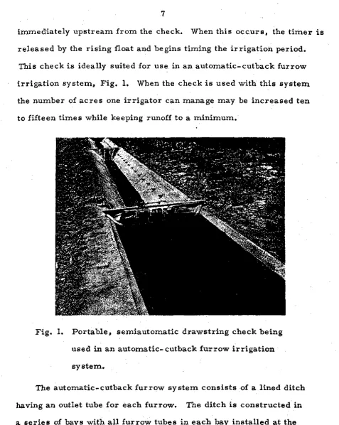
immediately upstream from the check. When this occurs, the timer is released by the rising float and begins timing the irrigation period.
This check is ideally suited for use in an automatic-cutback furrow irrigation system, Fig. 1. When the check is used with this system the number of acres one irrigator can manage may be increased ten to fifteen times while keeping runoff to a minimum.
•
Fig. 1. Portable, semiautomatic drawstring check being used in an automatic-cutback furrow irrigation system.
8
in the bay immediately upstream is decreased resulting in a reduced
or cutback secondary flow. At the same time, a high initial flow dis-charges into the furrows of the downstream section. Thus a high ini-tial or primary flow in each furrow is followed by a reduced secondary flow. This results in an efficient irrigation with a minimum of runoff from the field. The experimental systems installed to date are equip-ped with furrow tubes made from standard pipe without an adjustment for flow rate. Experience during the past season, however, indicates that it may be desirable to equip the furrow tubes with adjustable gates so that the flow to individual furrows, may be adjusted to compensate for variations in soil intake rates. Once adjusted the tubes should not re-quire further attention during the remainder of a season.
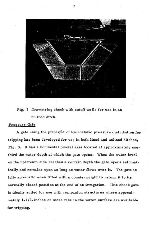
The basic drawstring check for lined ditches may also be used in unlined ditches by providing sheetrnetal cutoff walls instead of rubber
seals on the edges of the frame. With the cutoff walls attached, the structure is installed in an unlined ditch at approximately a 45 0 angle much the same as in a lined ditch, Fig. Z..
Drop Gate
The drop gate mentioned earlier has been tested in both lined and unlined ditches as a companion device to other automatic structures..
It is hinged at the top and in the open position is suspended over the top of the ditch.. When released, it falls by its own weight and stops the flow of water in the ditch or through the turnout where it is placed..
This timer-controlled gate is presently being used to irrigate sugar cane in Hawaii where in the past two years approximately 20,000 acres
Fig. 2 Drawstring check with cutoff walls for use in an unlined ditch.
Pressure Gate
A gate using the principld of hydrostatic pressure distribution for tripping has been developed for use in both lined and unlined ditches,
10
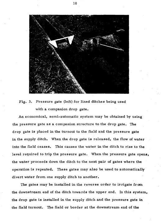
Fig. 3. Pressure gate (left) for lined ditches being used with a companion drop gate.
An economical, semi-automatic system may be obtained by using the pressure gate as a companion structure to the drop gate. The
drop gate is placed in the turnout to the field and the pressure gate in the supply ditch. When the drop gate is released, the flow of water into the field ceases. This causes the water in the ditch to rise to the level required to trip the pressure gate. When the pressure gate opens, the water proceeds down the ditch to the next pair of gates where the operation is repeated. These gates may also be used to automatically divert water from one supply ditch to another.
The gates may be installed in the reverse order to irrigate from the downstream end of the ditch towards the upper end. In this system, the drop gate is installed in the supply ditch and the pressure gate in
ditch is irrigated first. Irrigation of this section is terminated when the drop gate immediately upstream is released and stops the flow of water in the ditch. The water level above the drop gate rises until the pressure gate in the field turnout opens to admit water into the field. When irrigating in this manner, a safety feature is built into the sys-tem since only one irrigation set would be missed in case of a timer failure. The next structure upstream would operate at its scheduled
time.
Sinking Float Border Gates
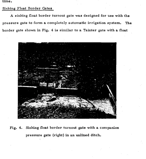
A sinking float border turnout gate was designed for use with the pressure gate to form a completely automatic irrigation system. The
border gate shown in Fig. 4 is similar to a Tainter gate with a float
12
mounted on the front portions The float is constructed with a water inlet at the bottom and a controlled air escape at the top. The float sinks at a rate controlled by the amount of air escaping. In opera-tion, the float initially is buoyant and opens the gate when water is received in the ditch. The gate is counterbalanced such that the buoy *. ant force from the float is sufficient to hold it open during irrigation. Irrigation is terminated when the float loses "buoyancyand sinks, thus closing the gate. The rate at which water is allowed to enter the float is controlled by varying the size and length of a stainless steel hypo-dermic needle on the air-escape tube. A removable, plastic cover is placed over the needle for protection. The float on the border gate is constructed so that it loses buoyancy rapidly when the top of the float sinks to the water level in the ditch. This causes the gate to close rapidly. When the border gate closes, the water level in the ditch rises until the pressure gate in the supply ditch opens. Water is thus allowed to flow to the next pair of structures downstream where the sequence is repeated. When water is turned from the ditch after field irrigation is completed, the check gate returns to its normally closed position. The float on the border gate drains between irriga-tions so that it becomes automatically reset and ready for the next irrigation without attention from the farm operator. Operation of the • structures referred to above is described in greater detail elsewhere
(1/)• (Ms (13).
Improved Efficiency with Automation
T
an overall irrigation efficiency of 87% (14). In addition to increasing the irrigation efficiency, this system reduced labor requirements more than 80%. Preliminary data obtained at the Research Center indicate that an irrigation efficiency as high as 75 to 80% may be obtained from an automatic-cutback furrow system.
Labor performance data from several sources are given in the following tabulation for conventional irrigation systems and for those equipped with automatic structures:
Data Source and Irrigation System
Average Labor Requirements
Per Acre Average Area Per. Irrigation Irrigated Per Hr.
Hours Acres
Manual Irrigation: Utah (19)
880 ft. or more length of run 0.39 330-660 ft. length of run .75 New Zealand (20)
Border dyke with 8 cfs flow .5 Hawaii (18) Sugar Cane
Hilly terrain, steep slopes .74 Level-level ditch system, mild slopes .42 With Automatic Equipment:
Automatic-cutback furrow irrigation system w/portable semi-automatic check dam
(Research Center and Colorado installations)
New Zealand
Automatic border dyke with 8 cfs flow .028
Nevada (14)
Drop gates and level basins .028
Hawaii
Hilly terrain, steep slopes .35 Level-level ditch system, mild slopes 0.14
. 029-• 04
14
These data are indicative of the labor savings which may result from the use of automated surface irrigation equipment. Data from the Utah
study are indicative of the irrigation requirements in the United States for good surface systems using concrete turnouts and headgates. The data are an average for both lined and unlined ditches. For systems which do not have permanent structures and which are not well designed or maintained, the labor requirements will be somewhat greater than shown. The labor requirement for the automatic-cutback furrow sys. tem is slightly greater than for the New Zealand and Nevada systems because the check dams were portable. The increased labor represents that required to move the portable check dams from one location to an-other. If sufficient checks were used so that they could remain in place, or if permanent automatic structures were used, labor requirements should be comparable to those reported for New Zealand and Nevada where the structures were permanently set in place.
Work is being conducted in some Soviet associated countries to reduce furrow irrigation labor requirements. A system has been dev-eloped for use in East Germany and Bulgaria (22) for automatically priming siphon tubes. Information pertaining to the system is some-what meager but the labor statistics reported are indicative of the in-creased performance which may result from automating or partially automating an irrigation system. The average productivity of an irri-gator in these countries is reported to be approximately from 0.4 to 0.6 hectare (1 to 1-1/2 acres) per shift with furrow irrigation on uneven ground using a hoe. On fairly level land and long runs the productivity
is approximately 2-1/2 to 3-1/2 hectare (6 to 9 acres) per shift. This
siphon tubes in lined ditches. By using automation in varying degrees, the labor performance was increased to 10 to 15 hectares (25 to 37 acres) per shift.
In addition to the labor and water savings resulting from the use of automated surface irrigation equipment, better water management can often result in increased yields. For example, irrigation effic-iency of mountain meadow systems is normally very low. Some of the timer controlled structures developed at the Research Center were
field tested on a mountain meadow field in Wyoming. The study involved the irrigation of two adjacent fields in which one field was irrigated in
the conventional manner with water applied almost continuously
through-out the irrigation season. The other field was equipped with automatic checks and good irrigation practice followed. Under the improved water management practice, the hay yield from the onc... crop normally harvested in that area was one-half to one ton per acre greater than on the field irrigated by conventional practice.
Future Outlook
An irrigation superintendent on a Hawaiian sugar plantation stated, "Automation or mechanization is causing a revolution in Hawaiian irri
gation." This same revolution will undoubtedly reach the mainland.
Automation of surface irrigation at present is somewhat limited by the availability of commercial equipment. With the various systems under 'development, irrigation equipment manufacturers most certainly will
16
REFERENCES
1. Bowman, C. C. Semi-Automation of Irrigation. Presented
at the Fourth Technical Conference on Irrigation, Drainage
and Flood Control, Phoenix, Arizona, March 27-29, 1968.
Proceedings Seventh International Congress on Irrigation
and Drainage, ICID, Mexico City, April 1969.
2. Calder, G. G. and L. H. Weston. Automitic System of Farm
Irrigation. New Zealand Journal of Agriculture, 112: (2),
February 1966.
3. Costel, G. L, , R. D. Berman, C. F. Becker, and G. A. Hood.
Testing and Development of Automatic Mechanical Equipment
for Surface Irrigation. University of Wyoming. Mimeographed
circular No. 146. March 1961.
4. Curtis, T. H. Changing Irrigation Sets by the Clock. Irrigation
Engineering and Maintenance, p. 14-15. December 1960
5. Divine, Ted. Bellevue, Idaho. Personal communication, 1968.
6. Fischbach, P. E., T. L. Thompson and L. E. Stetson. Automatic
Controls for Automatic Surface Irrigation System with Reuse
System. ASAE Paper No. 68-311. Presented at the Annual
Meeting, ASAE, Logan, Utah, June 18-21, 1968.
7. French, L. L., Powell, Wyoming. Per sonal communication, 1968.
8. Garton, J. E. Designing an Automatic Cutback Furrow Irrigation
System. • .1klahoma State University. Bulletin B-651, October 1966.
1.7
10. liaise, H. R., E. G. Kruse and Erie Leonard. Hydraulically
Controlled Butterfly Gates in Farm Lateral Turnouts for
Automation of Surface Irrigation Systems. ASAE Paper No.
68-244 presented at the Annual Meeting, ASAE, Logan, Utah,
June 18-21, 1968.
11. Humpherys, A. S. Control Structures for Automatic Surface
Irrigation Systems. Transactions of the ASAE, 10:(1) 21-23, 27,
1967.
12. Humpherys, A. S. Automatic Mechanical Irrigation Gates.
Presented at Fourth Technical Conference on Irrigation,
Drainage and Flood Control, Phoenix, Arizona, March 27-29,
1968. Proceedings Seventh International Congress on Irrigation
and Drainage, ICID, Mexico City, April 1969.
13. Humpherys, A. S. Mechanical Structures for Farm Irrigation.
Prepared for presentation at the ASCE Irrigation and Drainage
Specialty Conference, Phoenix, Arizona, November 13-15, 1968.
14. Kimberlin, Leon. Automatic Basin System Reduces Irrigation
Water and Labor Needs. Soil Conservation, 32:(2) 39,40,
September 1966.
15n Lobb, W. R. and A. D. Hall. Automatic Irrigation. New
Zealand Journal of Agriculture. 106:(4) 318-319, 321, 323, 325, 327.
16. Loomis, G. H. A Self-Propelled Irrigation System. Presented
at Annual Meeting, Rocky Mountain Section, ASAE, Logan,
18
17. Martin, Newell, Escondido, Calif., Irrigation System Inventor. Personal Communication with L. S. Willardson, Research Investigations Leader, Southwestern Irrigation Field Station, Brawley, California 1968.
18. Reynolds, W. N., Hawaiian Sugar Planters Assn., Honolulu, Hawaii, personal communication 1968.
19. Strong, D. C. Economic Evaluation of Alternative Facilities for Surface and Sprinkler Irrigation in Utah. Agricultural Experi-ment Station, Utah State University, Bulletin No. 433, pp 14-15,
1962.
20. Taylor, A. R. Notable Advance in Automatic Irrigation. New Zealand Journal of Agriculture, 111. :(4) 67-69, 71, September
1965.
21. Ugrekhelidze, Sh. V. and Ch. Muriranidze ..- Autorndtion of Diatribtition-of Irrigation Water Through Furrows. Gidrotekh i Mellor. 9:11-13. September 1963.