49
Copyright © 2016. Vandana Publications. All Rights Reserved.
Volume-6, Issue-3, May-June 2016
International Journal of Engineering and Management Research
Page Number: 49-56
Comparative Studies on Tensile and Impact Properties of 20 mm Thick
AISI SS 304 SMA (Shielded Metal Arc) And GMA (Gas Metal Arc) Butt
Welded Joints
Dilpreet Singh1, Taljeet Singh2, Avtar Singh3
1,2,3Mechanical Engineering Department, Chandigarh Engineering College, Landran, Mohali, INDIA
ABSTRACT
Fabrication challenges including joining of larger thicknesses of the order of 20 mm and above poses a great challenge as many problems are encountered during the welding. In view of the above facts welding of thick plates of AISI SS 304 grade it was decided to undertake the present work with different welding processes viz. SMAW & GMAW to study the problems and challenges faced during welding and to study various mechanical properties of 20 mm thick plates.
The main objective of this work was to investigate how SMAW and GMAW affect the microstructure of the weld metal and the HAZ under different welding conditions and consequently, how the mechanical properties viz. transverse tensile strength, ductility and impact toughness of the weld joints were affected. Butt welded joints were made using double V-groove design and welding was accomplished with SMAW (Shielded metal arc welding process) using 9 weld passes and GMAW (gas metal arc welding) using 8 weld passes. The fabricated joints were subjected to radiographic testing so as to make a fair assessment about the quality of the joints. The welded specimens were then subjected to transverse tensile testing and Charpy V-notch impact testing. Tensile results obtained from this study show that the average UTS value is 655.81MPa for base metal, 666.81MPa for the GMAW combination and 565.36MPa for SMAW combination. This shows that the welding of AISI 304 SS is beneficial with GMAW. The impact result show that the average impact value of base material is 163.3J. For SMAW it is 187J and similarly it shows that impact value of 176J for GMAW weld joints. The microstructural studies show that in GMAW continuous dendritic structure is formed in GMAW but in SMAW continuous dendritic structure is disturbed. This work in the present form has helped in establishing a correlation between the microstructure and the mechanical properties and proves to be useful as a welding procedure database for the fabrication industry using thick sections of AISI 304 SS grades.
Keywords--- AISI 304 SS, SMAW process, GMAW
process, Transverse tensile testing, Impact testing (Charpy
V-notch testing), Weld zone, HAZ, Microhardness, Microstructure
I.
INTRODUCTION
AISI304 stainless steel is an industrially important alloy. Out of 300 series grade of these steels type SS 304 is extensively used in industries due to its superior low temperature toughness and corrosion resistance. Additionally, for the industrial applications of the AISI 304 stainless steels, the different welding methods are used due to its simple assembly and/or joins on sheets, plates and/or pipes made out of this material. On the other hand, it is also imperative to highlight that during welding many discontinuities are produced, which acts as stress raisers that can lead to a decrease in the life of the weld. Therefore, the problems of this joining method have become an important issue of study in manufacture.
Two welding processes, i.e. SMAW and GMAW were selected from the operating envelope. Four plates each of size 150x65x20 mm which would form a double V-groove joint between them were used to make two finished weld pads of size 150x130x20 mm, i.e. one with SMAW and the other with GMAW process. The double V-groove design was used so that welding could be accomplished ensuring full penetration. Before welding all the edges were thoroughly cleaned mechanically and chemically in order to avoid any source of contamination like rust, scale, dust, oil, moisture etc. that could creep into the weld metal and later on, could result possibly into a weld defect.
50
Copyright © 2016. Vandana Publications. All Rights Reserved.
heat generated melts a portion of the electrode tip, its coating and the base metal in the immediate area. The weld forms out of the alloy of these materials as they solidify in the weld area. Slag formed to protect the weld against forming oxides, nitrides, and inclusions.
SMAW has many applications in the field of pipeline work, shipbuilding, maintenance and repair industries, offshore platforms, naval Industries and construction of steel structures [5]. Generally, the fabrication process involves the joining of stainless steel components by means of a suitable fusion welding process such as shielded metal arc welding (SMAW) [2]. This process is widely practiced in most of the industries for fabrication, maintenance and repair of welds [6]. Due to these reasons and their wide applications SMAW process was selected for the welding of AISI304 stainless steel
Gas metal arc welding (GMAW) is a welding process in which an electric arc forms between a consumable which heats the work piece metal, causing them to melt, and join. Along with the wire electrode, feeds through the welding gun, which shields the process from contaminants in the air. The process can be semi-automatic or semi-automatic. A constant power source is most commonly used with GMAW, but constant be used.
II.
METHODOLOGY
The present work was carried out to compare the studies on Tensile and Impact properties of 20 mm thick AISI 304 SS butt welded joints. Two welding processes, i.e. SMAW and GMAW were selected from the operating envelope. Four plates each of size 150x65x20 mm which would form a double V-groove joint between them were used to make two finished weld pads of size 150x130x20 mm, i.e. one with SMAW and the other with GMAW process. The double V-groove design was used so that welding could be accomplished ensuring full penetration. Before welding all the edges were thoroughly cleaned mechanically and chemically in order to avoid any source of contamination like rust, scale, dust, oil, moisture etc. that could creep into the weldmetal and later on, could result possibly into a weld defect.
Specification of the base material
The base material used in this study was AISI 304 stainless steel (rolled condition). The chemical composition of base metal is summarized in Table 1.
Table 1:- Chemical Composition of AISI 304 stainless steel, % weight
Elemen ts
C Si Mn P S Cu Cr
%weigh 0.0 0. 1.5 0.0 0.0 0.5 18.
t 741 47
3
9 34 4
206 25 62
Elemen ts
Ni M
o
Ti Al Sn Nb Fe
%weigh t 8.2 0 0. 20 9 0.0 061 6 0.0 03 35 0.0 192 0.0 167 69. 9
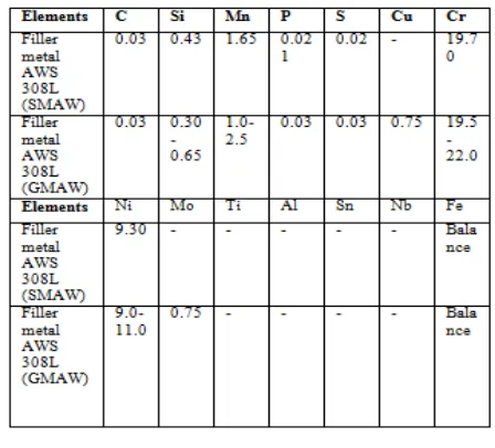
Welding Consumables used
The coated electrodes of 3.15mm and MIG wire of 1.2mm diameter of grade 308L were used for the present work. The chemical composition (wt. %) of filler material is summarized in Table 2.
Joint design
Double V joint design with 2mm root face and 2.5mm root gap with a groove angle of 60 degrees was used for the present study.
Using a welding current of 90-95A the root pass was first given to the plates with SMAW and the root pass of other two plates was given with GMAW by using 110A current.
Process parameters and their working range
The welding of plates has been carried out by using two welding processes, i.e. SMAW & GMAW. Shielded metal arc welding was carried out in 9 numbers of passes including root pass whereas the Gas metal arc welding was done with 8 passes including root pass. The process parameters used during different welding processes for fabricating butt welded joints are mentioned in Table 3 and 4 respectively.
Welding operation
51
Copyright © 2016. Vandana Publications. All Rights Reserved.
base material. So in accordance with this fundamental fact two different welding processes were used corresponding to different welding currents. The two plates to be welded were tacked Welding was carried out by an experienced welding operator. AWS 308L electrodes of 3.15mm and MIG wire of 1.2mm diameter were used to weld 304
stainless steel plates. The electrodes were baked in the oven for 45 min before welding to remove moisture. The numbers of passes taken for shielded metal arc welding were 9 and during gas metal arc welding were 8 respectively.
The weld bead sequence followed in these weld pads during the experimental work is shown in Fig. 3.4(a) & (b).
Figure 1:- Weld bead sequence in 20mm SMAW welded plates
Figure 2:- Weld bead sequence in 20mm GMAW welded plates
In actual welding, after a weld pass is laid, the weld plate is allowed to cool down at an interpass temperature of 175-200° C before the start of the next pass. In the present work, the average time gap of 2 minute was given between the successive passes. This duration was utilized to remove the slag formed during each pass.
During and after welding, the plates were visually inspected for their quality and it was ensured that both the weld beads possessed good geometrical consistency and were free from visible defects like surface porosity, blow holes etc. Figure 3 shows the plates in the as welded condition using different welding processes.
3 1
2
4
5 6
7 8
1 3 4 7
2 5
6 9
52
Copyright © 2016. Vandana Publications. All Rights Reserved.
Figure 3:- Photograph showing the base plates in the as welded condition with different welding processes
Considering an arc efficiency (η) of 0.75 for SMAW, the heat input per mm length of weld (Q) was calculated using the relation Q = ηVI/v, and these values are also shown in Tables 3 and 4.
IV.
RESULTS & DISCUSSIONS
Non-destructive testing
To understand any type of defects or discontinuities such as cracks, inclusions and porosity the radiography of the SMAW and GMAW welded plates have been carried out which is shown in Fig. 4 and 5.In
Figure 4:- X-ray radiography of SMAW welded plates
radiography there are mainly three levels i.e. level 1, 2 and 3 which represents the
quantity of defects in the material. In the present study the defects were found at level 1, i.e. the slag inclusion and porosity shows the minor effect on the welded plates.
Figure 5:- X-ray radiography of GMAW welded plates
In figure 4 radiography of SMAW welded plates have been carried out. The defects were found at level 1 i.e the slag inclusion. In figure 5 radiography of GMAW welded plates have been carried out. The defects found at level 1 i.e porosity. Both cases defects were at minor level.
The Table 5 shows the result of non-destructive testing on the welded joints of the AISI304 stainless steel plates. Any types of internal flaws or discontinuities such as cracks, shrinkage, hot tear, insert and molting have not been observed in the weldment. Only slag inclusion and porosity is there in the weld pads which is at level 1, i.e. at very minor level as discussed earlier.
Table 5 X-ray radiography results Type of defects Slag
inclusion
Porosity Internal shrinkage
Crack Hot tear Inser t
Molting
Results obtained from plate 1
Level-1 Nil Nil Nil Nil Nil Nil
Results obtained from plate 2
Nil Level-1 Nil Nil Nil Nil Nil
53
Copyright © 2016. Vandana Publications. All Rights Reserved.
Figure 6:- Schematic diagram showing the specimen sampling plan from the Butt welded plates (Top view)
Destructive testing
In order to determine mechanical properties of the welded specimens three type of tests were used viz. Tensile and impact testing. The specimens were taken from the weld pads as schematically illustrated in Figure 6.
Tensile test
The specimens were tested on a servo hydraulically controlled digital tensile testing machine.
Figure 7:- Schematic showing dimensions of tensile specimen used in the present work
Impact
specimen
6 mm
discarded
away
I2
I3 I1
T2
T1
T3
6 mm
discarded
away
54
Copyright © 2016. Vandana Publications. All Rights Reserved.
Tensile testing results
The transverse tensile strength of the joints made using different welding processes has been evaluated. In each condition three specimens were tested and the strength of the specimens corresponding to SMAW (9 pass) and GMAW (8 pass) joints and their corresponding percentage elongations, percentage reduction in area and yield stress thus obtained are mentioned in the Table 6.
Tensile results obtained from this study show that the average UTS value is 655.81MPa for base metal, 666.81MPa for the SMAW combination and 565.36MPa for GMAW combination. The fractured features of tensile tested specimens are shown in Figure 8.
Figure 8:- Transverse tensile tested specimens showing the location of fracture
Charpy impact test
The standard specimen is placed on specimen supports and the moving mass hit the specimen and fracture takes place. Energy absorbed by breaking specimen is measured in joule (J).
Three specimens for each welding combination were machined out from the weld pads as mentioned in Figure 6 and were prepared in accordance with ASTM E-23 standards. Impact specimens were made with a V-notch in a weld metal zone and HAZ so as to make an assessment of their toughness. The angle of V-notch is 450
Figure 9:- Standard impact test specimen size
Results of Impact test
Three specimens were tested for impact toughness in each condition. Table 7 shows the results of impact toughness observed from the base metal and weld metal zone (WM) for SMAW and GMAW joints.
From the above results it is found that the average impact value of base material is 163.3, for shielded metal arc welding it is 187J and similarly it shows the impact value of 176J for gas metal arc welded specimens. The fractured features of impact tested specimens were shown in Figure 10.
.The standard impact specimen size is shown in Figure
9. The charpy V-notch values indicating the impact energy absorption by each of the welded specimens were recorded.
Figure 10:- Charpy V-notch tested specimens showing the location of fracture
Table 6 Results from transverse tensile test
Specimen Name
Maximu m force (N)
Tensile strength (MPa)
% Elongation % reduction in area
Yield stress (MPa)
Location of fracture
Base metal
210,120 655.807 49.64 55.68 350.00 Base metal
SMAW (1)
222,420 657.484 24.720 30.828 305.951 Weld metal
SMAW (2)
225,260 666.221 37.160 29.213 319.243 Weld metal
SMAW (3)
229,560 676.718 47.280 27.040 339.155 Weld metal
55
Copyright © 2016. Vandana Publications. All Rights Reserved.
Table 7 Impact properties of welded joints with SMAW & GMAW processesSpecimen code
CVN value (J)
Specimen code CVN Value (J)
Specimen code CVN value (J)
BM (1) 164 SMAW (1) 184 MIG (1) 176
BM (2) 161 SMAW (2) 193 MIG (2) 168
BM (3 165 SMAW (3 190 MIG (3) 185
Metallurgical studies Micro hardness results
The microhardness was checked for base metal, weld zone and heat affected zone for and GMA welded specimens. At every place readings were taken. All the readings for brinnel hardness at 3000kg load, diameter 10mm ball, 10seconds time are shown in Table 8.
Table 8 Micro hardness (HBN) results
Specimen name
Parent metal(HBW)
Weld zone (HBW)
Heat affected
zone (HBW)
WJ-SMAW
186-190 254-258
222-228
WJ-GMAW
186-188 253-254
224-226
Analysis of the microhardness
Results represents the variation of micro hardness values obtained from the different sources such as base metal and welded condition. The hardness values of as-welded specimens were much greater than base metal. High hardness values were observed in the weld zone of the both weldments.
From the above observation it can be easily concluded that for both the welded plates microhardness variations in weld metal and heat effected zone had similar values. It was further found that weld zone of both the joints possessed hardness in a closer range followed the hardness of HAZ and unaffected base metal.
Microstructure of Butt welded joints
Figure 11:- Optical micrograph (100X) showing the microstructure of base metal
Figure 12 (a), (b):- Optical micrograph (100X) showing the microstructure of weld metal and HAZ (SMAW)
Figure 13(a, (b):- Optical micrograph (100X) showing the microstructure of weld metal and HAZ (GMAW)
Analysis of microstructure
In GMAW welded joints continuous dendritic structure is formed but in case of SMAW welded joints continuous dendritic structure is disturbed. In fusion boundary epitaxial growth is observed in both joints which gradually changes to competitive growth in center of weld zone. Further it is found from these the extent of grain coursing is higher in case of HAZ of SMAW joint or whereas not much grain coursing effect was observed in HAZ of GMAW.
V.
CONCLUSION
Based upon the present work the following conclusion have been drawn.
56
Copyright © 2016. Vandana Publications. All Rights Reserved.
• Based upon this comparative study it was foundthat the UTS for GMAW welded joints was higher than the UTS of base metal.
• Ductility of the welded joints measured as % elongation in present case was found to be higher in case GMAW (36.38%) joints as compare to the SMAW (24.37%) joints. The % reduction in area is greater in SMAW joints during transverse tensile test.
• This comparative study further shows that SMAW welded joints possessed maximum yield strength of 367.5 MPa followed by the base metal yield strength of 350 MPa and GMAW welded joints possessing 321.4 MPa yield strength.
• Charpy V-notch testing results shows that the weld metals of SMAW joints & GMAW joints possessed higher impact toughness than the base metal.
• It was further found that weld zone of both the joints possessed hardness in a closer range followed the hardness of HAZ and unaffected base metal.
Finally it could be concluded that although both SMAW & GMAW process can be effectively used for welded 20mm thick AISI 304 SS there is a variation among different properties of these joints.
Scope for future work
• Effect of welding parameters on the fatigue properties of thick plates of SS304 can be studied.
• Effect of different welding processes, filler, heat input and post weld heat treatments on the corrosion resistance properties of AISI 304 SS can be studied.
• Material characterization studies analysis can be enhanced by using techniques like X-ray diffraction (XRD), scanning electron microscope (SEM) and transmission electron microscope (TEM).
REFERENCES
[1] Woei-Shyan Lee a, Jen-I. Chenga, Chi-Feng Lin
Deformation and failure response of 304L stainless steel
SMAW joint under dynamic shear loading Materials
Science and Engineering A 381 (2004) pp. 206–215. [2] Subodh Kumar, A.S. Shahi Effect of heat input on the microstructure and mechanical properties of gas tungsten arc welded AISI 304 stainless steel joints
Materials & Design, Volume 32 (2011) pp. 3617-3623. [3] Andrés R. Galvis E, W. Hormaza Characterization of failure modes for different welding processes of
AISI/SAE 304 stainless steels Engineering Failure
Analysis, Volume 18 (2011) pp. 1791-1799.
[4] Nadkarni Modern arc welding process 4th Edition, Oxford & IBH publishing Co. Pvt. Ltd; New Delhi, India (1988).
[5] S Murugan, P.V Kumar, B Raj, M.S.C Bose
Temperature distribution during multipass welding of
plates International Journal of Pressure Vessels and
Piping, Volume 75 (1998) pp. 891-905. [6] WIKIPEDIA, The free encyclopedia.
[7] S Murugan, Sanjai K Rai, P.V Kumar, T Jayakumar, Baldev Raj, M.S.C Bose Temperature distribution and residual stresses due to multipass welding in type 304 stainless steel and low carbon steel weld pads
International Journal of Pressure Vessels and Piping, Volume 78 (2001) pp. 307-317.
[8] G Magudeeswaran, V Balasubramaniarr, G Madhusudhan, Reddy Z, T S Balasubrarnaniarr
[9] Effect of Welding Processes and Consumables on
Tensile and Impact Properties of High Strength Quenched and Tempered Steel Joints Journal of Iron and Steel Research, International (2007) pp. 87-94.
[10] O.P Khanna A textbook of Welding Technology 18th edition dhanpat rai pub. Ltd. New Delhi, India (2009). [11] A.Rajeshkar, G.Madhusudhan, T.Mohandas, V.S.R.Murti Influence of austenizing temperature on microstructure and mechanical properties of AISI 431SS electron beam welds Material and Design 30 (2009) 1612-1624.
[12] J.A.Brooks and W.M.Garrison Welds microstructure development and properties of precipitation-strengthened martensitic stainless steel Welding research supplement, August 1999, 280S-291S.
[13] Y.C. Lin, K.H. Lee
International Journal of Pressure Vessels and Piping, Volume 71 (1997) pp. 197-202
[14] Zhibo Dong, Yanhong Wei, Yanli Xu Predicting weld solidification cracks in multipass welds of SUS310 stainless steel Computational Materials Science, Volume 38 (2006) pp. 459-466.
[15] Ravindra Kumar, V.K. Tewari, Satya Prakash
Oxidation behavior of base metal, weld metal and HAZ regions of SMAW weldment in ASTM SA210 GrA1 steel