Please cite this article as: S. D. Rahate, A. D. Sarode, Design of Air Distribution System for Operation Theatre Using Flow Visualization Techniques to Improve Flow Characteristics, International Journal of Engineering (IJE), IJE TRANSACTIONS A: Basics Vol. 33, No. 1, (January 2020) 164-169
International Journal of Engineering
J o u r n a l H o m e p a g e : w w w . i j e . i rDesign of Air Distribution System for Operation Theatre Using Flow Visualization
Techniques to Improve Flow Characteristics
S. D. Rahate*, A. D. Sarode
Department of Mechanical Engineering, Lokmanya Tilak College of Engineering, University of Mumbai, Navi-Mumbai, India
P A P E R I N F O
Paper history: Received 04 April 2019
Received in revised form 01 November 2019 Accepted 07 November 2019
Keywords: Operation Theatre
Heat Ventilation and Air Conditioning CFD
Angular Air Distribution System
A B S T R A C T
Operation Theatre (OT) is the most important area where precise controlled on indoor air quality is required because it is directly related to patient health and its recovery period. This work aims to study and visualize the airflow distribution of conventional flat air diffuser ventilation system and newly designed angular air ventilation system in OT. Angular Air Distribution (AAD) system is designed in such way that, conditioned air is throw in OT with some angle so it can cover the maximum area of OT with laminar flow and minimum installation area. The performance of angular air distribution (AAD) system with varying inlet diffuser angle, constant 0.4m/s inlet velocity and air flow pattern are investigated with the help of numerical simulation and experimental setup of prototype OT model. Detail experimental investigation is done on a prototype with the help of a smoke test and camera target method (CTM). Both numerical and experimental results showed a similar pattern of air distribution for the various design configurations.
doi: 10.5829/ije.2020.33.01a.19
1. INTRODUCTION1
The main task of Heat Ventilation and Air Conditioning (HVAC) system in the modern hospital Operation Theatre (OT) is to provide a comfortable and healthy environment to the patient and surgeon. As ventilation system play important role in HVAC to keep OT environment free from bacteria. The poorly ventilated system not only affect the health of patient and surgeon from infection but also feel them uncomfortable [1]. In previous standard and guidelines, turbulent air flow was allowed in OT ,but recently published standards suggest to use Laminar Air Flow (LAF) systems [2]. Many national and international standards and guidelines are available for every country to design a ventilation system with environmental parameters for OT [3-6]. Alternate methods are mixing and displacement ventilation system which differs by the position of supply and an exhaust port in OT. Indoor obstacles can easily affect the unidirectional flow pattern of the ventilation system. Ventilation and air distribution pattern have a great effect on indoor air quality which includes indoor temperature,
*Corresponding Author Email: [email protected] (S. D. Rahate)
relative humidity, air flow velocity, pressure relationship, air movement’s efficiency. Therofore in this work new AAD system is designed in such a way that it will distribute the air in laminar pattern in whole OT. As per national and international standards and guidelines, the temperature in OT should be maintained at 18-22oC with
with a mathematical k-e model for validation purpose [9-11]. Sasan Sadrizadeh et al. [12] investigated the vertical and horizontal ventilation system in terms of sedimentation and bacteria distribution in operation theatre. He used the CFD software for numerical calculation and validate it by comparison with experimental data reported in the literature. Liu et al. [13] investigated an alternative of horizontal flow pattern and air flow performance in an OT. He also evaluates the effectiveness of the horizontal unidirectional airflow to control infectious airborne particles in operation theatre. In this study, the above drawbacks which is observed in literature is overcome by designing Angular Air Distribution (AAD) system. In AAD system, conditioned air is throw in OT with some angle so it can cover the maximum area of OT with laminar flow and minimum installation area. The designed AAD ventilation system is examined with the help of numerical simulation by varying inlet angles at , constant value and 0.4m/s inlet velocity. It is validated by experimental measurement and observations performed on prototype OT model. The air flow pattern of AAD system by varying inlet angles were tested with the help of smoke test. The air flow pattern obtained by the smoke of AAD system is captured by Camera Target Method (CTM) and it is validated with CFD contours plot results.air condition requirement
2. MATERIALS AND METHODS
2. 1. Numerical Model The 3D model of prototype
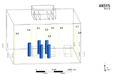
OR is modeled in CATIAV5 modeling software as shown in Figure 1. The OT room geometry that outline by a rectangular shaped room of wooden material with 1.524 m (L) x 1.524 m (B) x 0.9 m (H). Square ceiling supply diffuser (0.25 m2 surface area) and Four exhausts
(0.00580 m2 cross-section area) are arranged over two of
the opposite side wall. The operating bed is located at the middle area of OT under laminar flow. The five surgical staff each standing around the surgical table. They were modelled as cylinders. To investigate turbulence formation in air flow, Reynolds Averaged Navier Stokes (RANS) equations were employed to simulate the air flow field. It has been reported in the literature [11, 12], that the two equation RNG k-epsilon model is proper for indoor airflow simulation. This model was developed using renormalization. K-epsilon (k-ε) turbulence model is the most common model used in CFD to simulate mean flow characteristics for turbulence flow conditions [14, 15].
Conservation of mass equation:
∇ (𝜌 𝑣⃗ ) = 𝑆𝑚. (1)
Momentum:
∇ . (𝜌 𝑣⃗ 𝑣⃗ ) = −∇𝑝 + ∇. (𝜏̿) + 𝜌𝑔⃗ (2)
Figure 1. Solid model of OT with interior features and inlet-outlets
Where 𝜏̿ is viscous stress and can be written:
𝜏̿ = 𝜇 [(∇ 𝑣⃗ + ∇ 𝑣⃗𝑇) −2
3 ∇ . 𝑣⃗𝐼] (3)
Energyconservation:
∇ . (𝑣⃗ (𝜌 𝑣⃗ +𝑝) ) = −∇ . [∑ ℎ𝑗 𝑗𝐽𝑗] + 𝑆ℎ . (4)
Turbulence Kinetic Energy (k):
𝜕
𝜕𝑋𝑖(ρk𝑢𝑖) =
𝜕
𝜕𝑋𝑗[(𝜇 +
𝜇𝑡
𝜎𝑘)
𝜕𝑘
𝜕𝑋𝑗] + 𝐺𝑘+ 𝐺𝑏− 𝜌𝜀 −
𝑌𝑀+ 𝑆𝑘
(5)
Dissipation Rate of turbulence kinetic energy (ε)
𝜕
𝜕𝑋𝑖(𝜌𝜀𝑢𝑖) =
𝜕
𝜕𝑋𝑗[(𝜇 +
𝜇𝑡
𝜎𝜀)
𝜕𝜀 𝜕𝑋𝑗] 𝐶1𝜀
𝜖
𝑘 ( 𝐺𝑘+
𝐺3𝜀𝐺𝑏) − 𝐶2𝜀𝜌
𝜀2
𝑘 + 𝑆𝜀
(6)
𝐶𝜇 ,𝐶1𝜀, 𝐶2𝜀 𝜎𝑘 , 𝜎𝜀 are constant of turbulence model and their values are 𝐶𝜇,= 0.09, 𝐶1𝜀 = 1.44, 𝐶2𝜀 =
1.92, 𝜎𝑘 = 1.0, 𝜎𝜀 = 1.3
∇ is partialliy derivatives of quantity in all direction
Gk, Gb is generation of turbulence kinetic energy due to
the mean velocity gradient, Sh and Sm is strain tensor with
respect heat dissipation, SE, Sk is user defined source term
obtained by K and ε model equation, Sij is strain Tensor
in I and j direction and respective modulus and buoyancy. The values of physical properties of material used in numerical simulation are listed in Table 1.
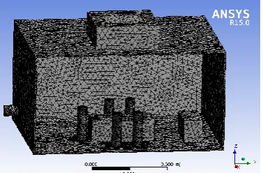
Figure 2 shows the mesh model of the OT. The different mesh size is considered for mesh independence study. Tetrahedron shaped cells were used with a varying number of elements of 256916, 287258, 312761, 39844, 586479. The velocity plot for different mesh size is
TABLE 1. Physical Properties of material used in numerical simulation
Material ρ (kg/m3) C
p (j/kg k) K (w/mk)
Wood 700 2310 0.173
plotted and it was approximately same for last four number of elements.The criteria for converged numerical solution are taken as 1e-3 RMS with element size 586479as shown in Figure 3.
Figure 3 shows the changes in velocity profile with OT height according to mesh element size. An inlet velocity is taken as 0.4 m/s with inside pressure as atmospheric. In this work, Ansys-Fluent 15.0 was used to solve the momentum, continuity and turbulence equations for fluid flow [15]. Since fluid flow is laminar and turbulence, standard wall function and turbulence k-e modk-el is usk-ed for analysis. Thk-e simulation was conducted under steady state condition. The number iteration is taken for selected K-epsilon model and solution are converged. Inlet velocity is taken as 0.4 m/s ,as inlet boundary condition with 5% turbulence intensity for a hydraulic diameter of OT. The exhaust port 1.3014 Pa pressure-outlet boundaries with no-slip boundary condition are combined with zero heat flux to define adiabatic walls.The walls of OT is considered as standard wall function including interior of OT.
2. 2. Experimental Setup The general layout
of the prototype model of OR with angular air distribution system is shown in Figure 4. It consists of two main parts such as air distribution system i.e. supply diffuser and interior. The OT prototype room model
Figure 2. Mesh model of OT
Figure 3. Velocity profile for different element size
made of wooden material. Which scale by 1:4 ratio of full scale of prototype.
In order to validate the results obtained from the CFD solution, a scaled model of OT is tested by experimental measurement i.e smoke test with help of CTM. For clear visualization of airflow pattern inside the OT, the interior is painted as black and white coloured smoke is used with air. A smoke generator liberates smoke which is accumulated in the mixing box. It is connected to inlet diffuser of OT by means of flexible ducts. The quantity and speed of the smoke are controlled by two valves which are placed on inlet and outlet port of the mixing box. The smoke entered in OT through inlet diffuser and exhausted to the atmosphere by outlet port which is placed at the bottom of the walls.Velocity is measured by
temperature compensate Hot wire anemometer
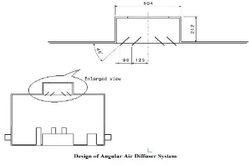
(Measuring Range: - NTC: -20 to 60 deg C, Accuracy: - ± (0.1 m/s + 5 % of mv) (0 to 2 m/s)) is measured inside the OT, Diffuser inlet and AHU outlet. To access all 27 points by annemometre probe, the length of probe is 3 meter long to measure the velocity at middle plane of OT. The velocity is measured on 9 lines fixture which is fixed at different location inside OT. The line fixture fixed with 3 measuring point at different height 200, 500, 700 mm from the floor (27 points) inside the OT, side wall of scale model is drilled with the hole to insert the probe of anemometer at different point as shown in Figure 1. AAD system is installed on ceiling at middle area of OT. AAD is square ceiling supply diffuser with 4 number of louvers equally spaced from edged of the diffuser is located in the central zone of the ceiling, that guide the unidirectional and angular flow by varying angle of louvers as shown in Figure 5.The aim of the test is to observe the airflow pattern and its distribution throughout the OT. The front side of the prototype is kept transparent so that clear images can be captured. The camera is fixed at its position using a tripod and the smoke is fed to flow inside the prototype. For smoke visualization test, smoke generator (Power: - 900watt, heat up time -12 min, capacity-3 liters) with fog fluid (white cloud) is used.
The smoke is stored in the mixing chamber to reduce the velocity, mixing chamber act as an accumulator, and the flow rate of smoke is controlled by valves. The interior features of OT and the white smoke is targeted and its images are captured by high definition digital camera. Initially, smoke visualization test is carried out to ensure no-leakage in the room. Further smoke visualization test was carried out to identify the air flow pattern with different inlet angle of AAD system and to evaluate the effectiveness of the same system.
3. RESULTS AND DISCUSSION
The velocity measurements and air flow pattern were taken from the ceiling to the floor on middle plane of scale model OT with constant velocity 0.4 m/s and outlet
pressure atmospheric. The separate CFD and
experimental analysis are taken for 3 cases of AAD system with 90O, 60O,45O angle of louvers.
From Figures 6-8 the air stream after striking the bed gets reflected upward causing the vortex. This vortex spread over the OT and mixes with fresh incoming primary airflow. These vortexes cause temperature draft (Canada effect) and turbulence in the flow of harmful particles along with the airstream flow over the surgeons and remain in the critical zone.
From Figures 9-11. it is observed that air velocity in critical zone is varying from 0.2-0.3 m/s, which is in
Figure 5. Enlarge view of Angular diffuser
Figure 6. Velocity Plot for OT with a flat diffuser
Figure 7. Velocity Plot for OT with 60O Angular diffuser
Figure 8. Velocity Plot for OT with 45O Angular diffuser
acceptable range as mentioned in national and international standards and guidelines.
Figure 9. Velocity distribution graph for flat diffuser
Figure 11. Velocity distribution graph for AAD system with 45o angle
From Figure 12 it is observed that in case of flat diffuser air velocity in non critical zone vary from 0 to 0.4 m/s, which results in turbulence formation in that area, but in other case i.e. 60o and 45o AAD system the
velocity variation in non critical zone is less which reduced the turbulence formation. For visualization of air flow pattern in AAD system with different angle 90, 60, 45,various images have been taken by the camera and the smoke is visualized inside the OT as shown in Figures 13-14. The smoke flow spreads and it forms vortices when it touches the operating table and surgeons and its flows in the opposite direction of the primary flow. Figures 13 and 14 present the path line exit from AAD system with 60° and 45° angle of louvers. The smoke flow
from diffuser reaches to the middle plane of OT with minimum turbulence. The throw of AAD system seems as long and equally spread in whole OT; therefore there is no vortex formation in OT.
Figure 12. Smoke visualization for flat diffuser (a) No smoke (b) Initial stage (c) Straight flow (d) vortex formation (e) mixing of primary and secondary flows (f) high amount of vortex formation and poor exhaust
Figure 13. Smoke visualization for AAD system with a 60O
angle (a) No smoke (b) Initial stage (c) Angular flow (d) Angular spread of smoke (e) Spreading of smoke beyond critical zone (f) equally spread smoke with a minimum vortex in whole OT with a proper exhaust.
Figure 14. Smoke visualization for AAD system with 45O angle
(a) No smoke (b) Initial stage (c) Angular flow (d) Angular spread of smoke (e) Spreading of smoke beyond critical zone (f) equally spread smoke with minimum vortex in whole OT with proper exhaust
4. CONCLUSION
the inlet surface area of the flat diffuser or to provide angular flow over the critical zone. It is achieved by implementation of AAD system. AAD ventilation system provides unidirectional flow in whole OT with maximum sterile zone.It will not affect the interior of OT, it cover the required air flow volume of OT with unidirectional flow as per requirement. It has easy fabrication and installation process.
5. ACKNOWLEDGMENTS
The authors acknowledged the financial support from University of Mumbai under Minor Research Grant Project (Research Project Number 384) in the academic year 2018-2019 in Lokmanya Tilak College of Engineering, Navi Mumbai, India
6. REFERENCES
1. Ho, S.H., Rosario, L. and Rahman, M.M., "Thermal comfort enhancement by using a ceiling fan", Applied Thermal Engineering, Vol. 29, No. 8-9, (2009), 1648-1656.
2. Van Gaever, R., Jacobs, V.A., Diltoer, M., Peeters, L. and Vanlanduit, S., "Thermal comfort of the surgical staff in the operating room", Building and Environment, Vol. 81, No., (2014), 37-41.
3. Jones, W.P., "Air conditioning engineering, Routledge, (2007). 4. Paul Ninomura, P. and Richard Hermans, P., "Ventilation
standard for health care facilities", ASHRAE Journal, Vol. 50, No. 10, (2008), 52 - 57.
5. Health, A.A.o.A.f. and Institute, F.G., "Guidelines for design and construction of hospital and health care facilities, Aia Press, (2001).
6. Normung, D.I.f., Din 1946-4, ventilation and air conditioning— part 4: Vac systems in buildings and rooms used in the health care sector. 2008, DIN Berlin, Germany.
7. Humphreys, H. and Taylor, E., "Operating theatre ventilation standards and the risk of postoperative infection", Journal of Hospital Infection, Vol. 50, No. 2, (2002), 85-90.
8. Balaras, C.A., Dascalaki, E. and Gaglia, A., "Hvac and indoor thermal conditions in hospital operating rooms", Energy and Buildings, Vol. 39, No. 4, (2007), 454-470.
9. Chow, T.-T. and Yang, X.-Y., "Performance of ventilation system in a non-standard operating room", Building and Environment, Vol. 38, No. 12, (2003), 1401-1411.
10. Chow, T.-T. and Yang, X.-Y., "Ventilation performance in operating theatres against airborne infection: Review of research activities and practical guidance", Journal of Hospital Infection, Vol. 56, No. 2, (2004), 85-92.
11. Chow, T. and Yang, X., "Ventilation performance in the operating theatre against airborne infection: Numerical study on an ultra-clean system", Journal of Hospital Infection, Vol. 59, No. 2, (2005), 138-147.
12. Sadrizadeh, S., Holmberg, S. and Tammelin, A., "A numerical investigation of vertical and horizontal laminar airflow ventilation in an operating room", Building and Environment, Vol. 82, No., (2014), 517-525.
13. Liu, J., Wang, H. and Wen, W., "Numerical simulation on a horizontal airflow for airborne particles control in hospital operating room", Building and Environment, Vol. 44, No. 11, (2009), 2284-2289.
14. Ufat, H., Kaynakli, O., Yamankaradeniz, N. and Yamankaradeniz, R., "Investigation of the number of particles in an operating room at different ambient temperatures and inlet velocities", International Journal of Ventilation, Vol. 17, No. 3, (2018), 209-223.
15. Ayremlouzadeh, H. and Ghafouri, J., "Computational fluid dynamics simulation and experimental validation of hydraulic performance of a vertical suspended api pump", International Journal of Engineering-Transactions B: Applications, Vol. 29, No. 11, (2016), 1612-1620.
Design of Air Distribution System for Operation Theatre Using Flow Visualization
Techniques to Improve Flow Characteristics
S. D. Rahate, A. D. Sarode
Department of Mechanical Engineering, Lokmanya Tilak College of Engineering, University of Mumbai, Navi-Mumbai, India
P A P E R I N F O
Paper history: Received 04 April 2019
Received in revised form 01 November 2019 Accepted 07 November 2019
Keywords: Operation Theatre
Heat Ventilation and Air Conditioning CFD
Angular Air Distribution System
هدیکچ
یتایلمع رتائت
(OT)
روط هب اریز تسا مزلا هناخ لخاد یاوه تیفیک رب نآ قیقد لرتنک هک تسا یا هقطنم نیرتمهم میقتسم
هدنکارپ اوه هیوهت متسیس زا اوه نایرج عیزوت مسجت و یسررب فده اب راک نیا .تسا طبترم نآ دوبهب هرود و رامیب تملاس اب
رد هدش یحارط هزات یا هیواز اوه هیوهت متسیس و یلومعم اوه
OT
یا هیواز یاوه عیزوت متسیس .تسا هدش ماجنا
(AAD)
، هک تسا هدش یحارط یا هنوگ هب رد یا هیواز اب عوبطم یاوه
OT
تحاسم رثکادح دناوتب ات دوش یم باترپ
OT
اب ار
یا هیواز یاوه عیزوت متسیس درکلمع .دهد ششوپ بصن لحم لقادح و هیلا دنچ نایرج
(AAD)
راشتنا توافتم هیواز اب
یدورو تعرس ، زیرپ 0.4
یزاس هیبش کمک اب اوه نایرج یوگلا و هیناث رد رتم یلیم لدم یشیامزآ یزادنا هار و یددع
هنومن
OT
نیبرود فده شور و دود تست کمک اب هیلوا هنومن یور رب تایئزج یبرجت یسررب .تسا هدش یسررب
(CTM)
داد ناشن یحارط فلتخم تامیظنت یارب اوه عیزوت زا هباشم یوگلا کی یبرجت و یددع جیاتن ود ره .دوش یم ماجنا
.