International Journal of Transpotation Engineering,
Rock
Slope
Stability
Analysis
Using
Discrete
Element
Method
0RKDPPDG5H]D0DOHNL-DYDQ1, Fouad Kilanehei 2, Amir Mahjoob 3
Received: 20.06.2014 Accepted: 15.01.2015
Corresponding author E-mail: [email protected]
1.Assistant Professor, Department & Civil Eng.University of Tehran, Tehran, Iran.
2. Assistant Professor, Department of Civil Engineering, Imam Khomeini International University, Qazvin, Iran. 3. Assistant Professor, Road, Housing & Urban Development Research Center, Tehran. Iran.
Abstract
Rock slope stability depends very much on the strength features of the rock and the geometrical and strength characteristics of the discontinuities (e.g., roughness, wall strength and persistence). Since a rock mass is not a continuum, its behavior is dominated by such discontinuities as faults, joints and bedding planes. Also, Rock slope instability is a major hazard for human activities and often causes economic losses, property damage (maintenance costs), as well as injuries or fatali-ties. A computer program has been developed in this research study to perform the stability analy-sis of a rock slope using the Discrete Element Method (DEM). The rock in the present model is treated as some blocks connected together by elasto-plastic Winkler springs. This method, the for-PXODWLRQRIZKLFKVDWLV¿HVDOOHTXLOLEULXPDQGFRPSDWLELOLW\FRQGLWLRQVFRQVLGHUVWKHSURJUHVVLYH IDLOXUHDQGLVDEOHWR¿QGWKHVOLSVXUIDFHRUXQVWDEOHEORFNV7RGHPRQVWUDWHWKHDSSOLFDELOLW\DQG XVHIXOQHVVRIWKHPHWKRGVHYHUDOH[DPSOHVKDYHEHHQSUHVHQWHGIRUWKHDQDO\VLVDQGRSWLPL]DWLRQ of the rock slope stabilization.
1. Introduction
Rock slope stability depends very much on the strength features of the rock and the geo-metrical and strength characteristics of the discontinuities (e.g., roughness, wall strength DQG SHUVLVWHQFH >/LQ HW DO @ 6LQFH D rock mass is not a continuum, its behavior is dominated by such discontinuities as faults, joints and bedding planes. In general, discon-tinuities (presence/absence) have profound LQÀXHQFH RQ WKH VWDELOLW\ RI URFN VORSHV DQG their behavior plays a critical part in a stabil-ity evaluation. Several authors have used the numerical discontinuum modeling method to analyze slope stability problems, [Cund-DOO@(DVNLHWDOXVHGWKHDERYH method and constructed a model of a natural slope to observe the instabilities caused by H[FDYDWLRQV QHDU WKH WRH >(DVNL HW DO @ =KDQJHWDOFDUULHGRXWVWXGLHVRQWKH dynamic behavior of a 120 m-high rock slope of China’s Three Gorges Dam ship lock using the discrete element model. They found good agreement between the numerical results and WKH ¿HOG PHDVXUHPHQWV RI WKH UHVLGXDO GLV -SODFHPHQWV RI WKH URFN VORSH GXULQJ WKH H[ -FDYDWLRQXQORDGLQJVWDJH>=KDQJHWDO@ +HX]HHWDOLOOXVWUDWHGWKHXVHIXOQHVV of the discrete element approach for the anal-ysis of rock mass mechanical behavior dur-ing wave propagation due to seismic events or rock blasting and concluded that although FRQWLQXXPFRGHVDUHTXLWHXVHIXOLQVLPXODW -ing some ground shock effects, they are not DGHTXDWHIRUUHSUHVHQWLQJG\QDPLFEORFNPR -WLRQSURFHVVHV>+HX]HHWDO@
It is to be emphasized that in all the above cases, use has been made of the Coulomb-slip constitutive model for joints deformations be-cause it has been a common practice to use &DQGijSDUDPHWHUVWRPRGHOWKHEHKDYLRURI discontinuities by a linear Coulomb relation.
Discrete Element Method (DEM) can be used for the numerical analyses of different geo-WHFKQLFDOSUREOHPVWRR,WZDVSUHVHQWHG¿UVW E\&6&KDQJDQGDV a new concept to investigate the bearing ca-pacity of foundations and stability of slopes DQG UHWDLQLQJ ZDOOV .LP HW DO XVHG DEM and analyzed nailed earth slopes [Kim [email protected][SODLQHG the static and dynamic loading conditions in DEM code for high rock slopes [Kveldsvik et DO@5DWKRGHWDOXVHG'(0IRU the analysis of static and dynamic response of dam abutments with a liner Coulomb slip con-stitutive model [Rathod, Shrivastava and Rao, @/LQHWDOFRQGXFWHGWKHG\QDP -ic analysis of rock slope based on pract-ical seismic load and performed collapse analysis of the crack development in a rock slope [Lin [email protected]\]HGD 100 m high natural hill slope composed of ba-salt using the DEM code for dry and saturated FRQGLWLRQV >.DLQWKROD HW DO @ 6WDELOLW\ analysis of Surabhi landslide in the Dehradun and Tehri located in India, was simulated nu-merically using the distinct element method E\3DOHWDO>3DOHWDO@6KHQDQG$EEDV (2013) developed and applied the random set distinct element method in the stability analy-sis of a rock slope from China [Shen and Ab-EDV@
In this method, stresses on all blocks’ interfac-es are compatible with the deformations and fully satisfy the stress-displacement relation-ship without any further assumptions. This PRGHODVOLJKWH[WHQVLRQRIWKHFRQYHQWLRQDO OLPLWHTXLOLEULXPDQDO\VLVSHUPLWVDVROXWLRQ WKDWVDWLV¿HVDOOHTXLOLEULXPDQGFRPSDWLELOLW\ conditions.
International Journal of Transpotation Engineering, solid slices connected together with Winkler
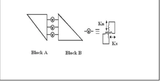
springs (compression, tension and shear) (Fig-XUHWRHVWDEOLVKDXQLTXHERXQGHGV\VWHP Normal springs behave elasto-plastically and induce rotational as well as normal stiffness; they do not yield in compression, but they do in tension cut-offs. Shear springs yield at shear capacity according to Mohr-Coulomb FRQVWLWXWLYHPRGHO)LJXUH%ORFNVJUDYLW\ forces are applied during the analysis.
,QHDFKFDOFXODWLRQVWHSZKLOHDVVXPLQJHTXLY -alent secant stiffness for the Winkler springs, the load is increased until the spring stresses H[FHHG WKH DOORZDEOH YDOXHV DQG ZKHQ WKLV
happens at a certain interface, its local fac-WRU RI VDIHW\ LV DVVXPHG DV DQG WKH H[FHVV stresses are redistributed among the neighbor-ing slices through the iteration process. This continues until the stresses on all interfaces are compatible with the deformations and ful-ly satisfy the stress-displacement relationship. Failure of rock joints shear springs depends on the joint’s shear resistance properties. The authors have applied the method to the stability analysis of rock slopes and developed a computer program with which they have ZRUNHGRXWVHYHUDOH[DPSOHVWRGHPRQVWUDWH the method’s applicability.
Figure 1. Winkler springs between two adjacent slices
)LJXUH%HKDYLRXURID:LQNOHUVSULQJ
3. DEM Formulation
&RQVLGHU WZR QHLJKERXULQJ EORFNV $ DQG % (Figure 3). The relative displacement between WKHVOLFHVFDQEHFDOFXODWHGXVLQJ(T
(1)
ZKHUH XD XE DQG ȦD ȦE DUH WKH GLVSODFH -PHQWVDQGURWDWLRQVRIEORFNV$DQG%UHVSHF -tively, P is a point located at the middle of the interface of the two blocks, and r is a vector connecting block A’s centre of gravity to point P. If one of the blocks remains immobile, its GLVSODFHPHQWVDUHVHWWREH]HURLQ(T Vector npFRVĮVLQĮLVGH¿QHGDVDQLQZDUG
unit vector normal to the face of block A at SRLQW3ZKHUHLQĮLVWKHDQJOHLWPDNHVZLWK WKH [ D[LV QRUPDO WR LW LV Qp VLQĮ FRVĮ 1RZ XVLQJ (T EHORZ WKH GLVSODFHPHQW YHFWRURQWKHOHIWVLGHRI(TFDQEHWUDQV -IRUPHGIURPWKHJOREDOFRRUGLQDWHV\VWHP[ y) to the local coordinate system (n-s).
If kn and ks are respectively the normal and shear constants per unit length of the Winkler spring, the interface force between the two blocks can be calculated as follows:
Figure 3. Two adjacent blocks
° ¿ ° ¾ ½ ° ¯ ° ® » » » ¼ º « « « ¬ ª ° ¿ ° ¾ ½ ° ¯ ° ® » » » ¼ º « « « ¬ ª ° ¿ ° ¾ ½ ° ¯ ° ® ' ' ' a a y a x ap y a p y b b y b x b p y bp y p p y p x u u r r u u r r Z Z
Z 0 1 1
1 0 0 1 1 1 0 1 0 0 1 (2) (3)
where KȦ = knL3/12 ; K
s = ksL ; Kn = knL and
L is the interface length.
The interface forces in the global coordinates V\VWHP FDQ EH GHWHUPLQHG XVLQJ (T DQG the forces acting on all sides of a block can be IRXQGXVLQJ(TZKLFKLVGHULYHGIURPWKH HTXLOLEULXPHTXDWLRQV (4) (5)
> @
^ `
p p p y p x b p y bp y p p s p n R r r ' ° ¿ ° ¾ ½ ° ¯ ° ® ' ' ' » » » ¼ º « « « ¬ ª ° ¿ ° ¾ ½ ° ¯ ° ® ' ' ' ZZ 0 1 1
1 0
0 1
> @
^ `
p p p s p n s n p p s p n K K K K M F F ' ° ¿ ° ¾ ½ ° ¯ ° ® ' ' ' » » » ¼ º « « « ¬ ª ° ¿ ° ¾ ½ ° ¯ ° ® Z Z 0 0 0 0 0 0International Journal of Transpotation Engineering, where fa
n, f a
s and m
a are respectively the body
forces and the moment acting on a block, and FDQ LQFOXGH JUDYLW\ LQHUWLD HDUWKTXDNH DQG loading forces.
&RPELQLQJ(TXDWLRQVWRZLOOUHVXOWLQ (T EHORZ ZKLFK VKRZV WKH UHODWLRQVKLS between the forces and displacements of a block.
(6)
It is obvious that for N blocks in the analysis, ZHKDYH1HTXDWLRQVDQG1XQNQRZQYDUL -ables (fa
n, f a
s and m
a for each block). 3.1 Failure of Winkler Springs
)RUHDFKEORFNWZRLQWHUQDODQGH[WHUQDOORDG vectors are introduced; the latter is established on the basis of the loads applied to the sys-tem and the former is induced in the springs DV D FRQVHTXHQFH RI UHODWLYH GLVSODFHPHQWV between slices.
Computation convergence, a necessity when incremental loading procedure is adopted in each calculation cycle, is accomplished when LQWHUQDO DQG H[WHUQDO ORDG YHFWRUV EHFRPH HTXDO $V PHQWLRQHG HDUOLHU ZKHQ D VSULQJ fails, its stiffness is changed by the secant method; therefore, the system does not con-YHUJHLQWKH¿UVWLWHUDWLRQ7KHH[FHVVVWUHVV appearing as the difference between the inter-QDODQGH[WHUQDOORDGYHFWRUVLVUHGLVWULEXWHG among the neighbouring slices. The iterative procedure continues until the stresses in the interfaces of all blocks are compatible with the deformations and fully satisfy the stress-displacement relationship.
3.2 Winkler Spring Stiffness
$VVKRZQLQ(TWKHPHWKRGUHTXLUHVNQ and ks (Winkler spring’s stiffness values);
^ `
> @
> @ > @> @
> @
^ `
> @
^ `
b b a aT T a a u R u R T K T R f
¦
&KDQJ>@VKRZHGWKDWWKH\KDYHLQVLJQL¿FDQW effects on the computed results. The ratio (kn/ ks) plays an important role (similar to that of the soil’s Young and shear moduli) in the DQDO\VLVDQGLVHTXDOWRȞIRULVRWURSLF elastic materials (usually ranging from 2 to 3).4. Computer Program
%DVHG RQ WKH IRUPXODWLRQ GHVFULEHG WKH DX -thors have developed a 2-D FORTRAN com-puter program that can analyse different-shape rock slopes with any sets of joints. The pro-gram has an interface that shows the slope’s joints and the un-deformed shape (the failed joints are in red); so, the progressive failure and the deformed slope and its blocks can be observed in the program interface.
0RGHO9HUL¿FDWLRQ
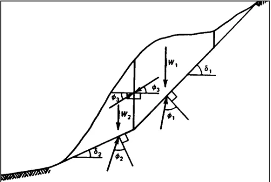
0RGHOYHUL¿FDWLRQLVGRQHE\FRPSDULQJWKH program results with those of the analytical VROXWLRQ RI WKH VLPSOH WZREORFN H[DPSOH Figure 3 shows a sliding surface that is joined ZLWK DQRWKHU ÀDWWHU VXUIDFH DW WKH WRH RI WKH slope. The strength reserve in the toe (the pas-VLYH UHJLRQ UHVWLQJ RQ D UHODWLYHO\ ÀDW VOLG -LQJVXUIDFHLVRYHUFRPHE\WKHH[FHVVIRUFH transmitted from the upper region (the active block that cannot remain at rest by the friction along its basal surface alone).
Analysis of the force system shown in Figure 3 yields:
(7)
where M1,M2,M3 are the friction angles related to slip along the upper, lower and vertical sur-IDFHVUHVSHFWLYHO\į1DQGį2 are the inclina-tions of the upper and lower slip surfaces, respectively, W1 and W2 are respectively the
weights of the active and passive blocks per XQLWRIVOLSZLGWK)LVWKHWKUXVWUHTXLUHGLQ WKHSDVVLYHEORFNWRUHDFKOLPLWLQJHTXLOLEUL -um (stable, if F > 0 and unstable if F < 0). Assuming W1 200 t, ,
, , and , we mod-HOOHGWKHH[DPSOHE\WKH'(0SURJUDPFRP -pared the results with those of the analytical solutions and found good agreement between them (Figs. 1 and 2). The red colour in each joint indicates that shear failure has occurred
in the joint; this gives a good insight on the condition of each joint and helps in optimiz-ing the slope stabilization. Furthermore, the normal and shear stresses in each joint can EHGH¿QHGDQGEORFNVGLVSODFHPHQWVFDQEH observed in the DEM method where stresses in all blocks interfaces are compatible with their deformations and fully satisfy the stress-displacement relationship without any further assumptions.
International Journal of Transpotation Engineering, Figure 6. , , F .6 t or , , F .2 t
6. Rock Slope Analysis using the DEM
5HVXOWVRIVHYHUDOH[DPSOHVDUHSUHVHQWHGWR show the DEM’s applicability for the stability analysis of rock slopes and its usefulness in RSWLPL]LQJ WKH VORSH VWDELOL]DWLRQ ([DPSOHV include the stability analyses of a slope with two sets of perpendicular joints, a slope with inclined layers, and a toppling mode.6.1 Stability Analysis of a Slope with Two Sets of Perpendicular Joints
7KLVH[DPSOHFRQVLGHUVDVORSHZLWKWZRVHWV of perpendicular joints with the following data:
H=5 m c=0 t/m2ij ÛȖ WP3
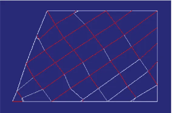
Figure 7 shows the rock slope model and the joints directions. The red colour in each joint indicates that shear failure has occurred at the joint.
Figure 7. Stability analysis of a slope with two sets of perpendicular joints
Figure 8 shows blocks displacements and in-GLFDWHVWKDWIDLOXUHKDVRFFXUUHGLQWKLVH[DP -ple. Figs. 7 and 8 help us decide how we can stabilize the slope by the removal of unstable EORFNV7KHVL[XSSHUEORFNVKDYHSURGXFHGD failure surface and have large displacements, so we can easily decide to remove them and UHH[DPLQHWKHVORSHVWDELOLW\)LJXUHVKRZV that blocks removal has caused the slope to become stable.
Figure 8. Rock blocks displacements in a slope with two sets of perpendicular joints
)LJXUH6WDELOLW\DQDO\VLVRIWKHVORSHZLWKWKHUHPRYDORIXQVWDEOHEORFNVVORSHLVVWDEOH
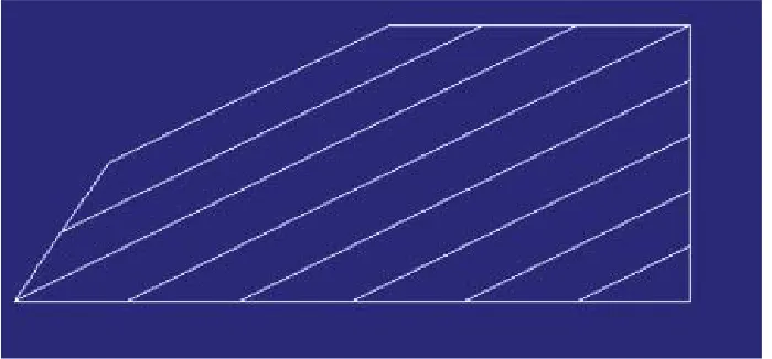
6.2 Stability Analysis of a Slope with In-clined Layers
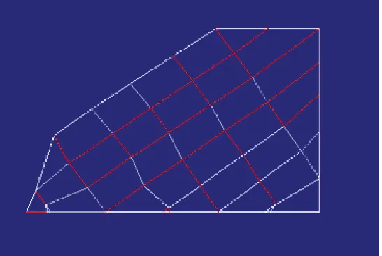
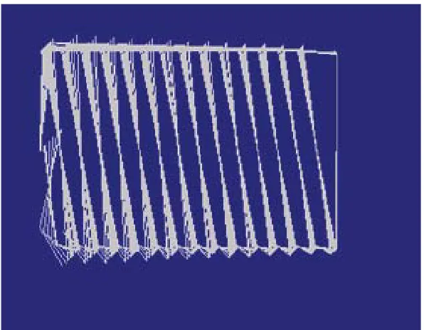
The rock slope in this analysis is the same as that in the previous section, but with inclined layers. During the analyses, blocks weights were applied in steps. The rock slope model and joints directions are shown in Figure 10 and blocks displacements (in the steps) in Fig-ure 11.
International Journal of Transpotation Engineering, shows that the slope is still unstable, the
sec-ond one (Figure 13) implies that block remov-al has caused the slope to become stable, and the third one (Figure 14) shows the effects of a berm on the slope and reveals how applying a berm can increase the stability of the slope.
%ORFNVGLVSODFHPHQWVGXULQJVHYHUDOVWHSVLQ the analyses are shown in Figure 15. Compar-ison reveals that the slope in Figure 14 needs more block removal than the one in Figure 13 to become stable.
Figure 10. Rock slope model and joints directions (red colour indicates that shear failure has oc-curred at the joint)
Figure 11. Rock blocks displacements
Figure 12. Stability analysis of slope with block removal (the slope is still unstable)
Figure 13. Stability analysis of slope with block removal (the slope is stable)
International Journal of Transpotation Engineering, 6.3 Toppling Mode Stability Analysis
The rock slope for the modelling of the top-pling mode is similar to that in Section 6.1, but with near vertical joints. Figure 16 shows the model and joints directions and Figure 17
Figure 15. Displacements of rock blocks in a bermed slope with inclined layers
shows the blocks displacements and indicates WKDW IDLOXUH KDV RFFXUUHG LQ WKLV H[DPSOH ,W is evident from Figure 16 that block removal cannot stabilize the slope because shear fail-ure has occurred in all the joints.
Figure 16. Stability analysis of a toppling mode
7. Conclusions
In this study, the Discrete Element Method (DEM) was adopted for the stability analyses of rock slopes. To demonstrate its applicabil-ity and usefulness in analyzing and optimiz-LQJ WKH VORSH VWDELOL]DWLRQ VHYHUDO H[DPSOHV including the stability analyses of a slope with inclined layers, a slope with two sets of perpen-dicular joints, and a toppling mode have been presented and its advantages over the conven-WLRQDOOLPLWHTXLOLEULXPPHWKRGKDVDOVREHHQ discussed. Progressive failure with which the VOLSVXUIDFHRUXQVWDEOHEORFNVFDQEHGH¿QHG is a subject considered in this method; there-fore, the method helps in optimizing the rock slope stabilization. The proposed method is theoretically rigorous and simple; it can eas-ily treat such more complicated problems as a slope with inhomogeneous properties and forces acting or foundations resting on a slope.
References
&KDQJ&6³'LVFUHWHHOHPHQWPHWK
-Figure 17. Displacements of rock blocks in the stability analysis of a toppling mode
od for bearing capacity analysis”, Computers and Geotechnics, 12, pp. 273-288.
&KDQJ & 6 ³'LVFUHWH HOHPHQW PHWKRG IRU VORSH VWDELOLW\ DQDO\VLV´ -RXUQDO of Geotechnical Engineering, 118(12), pp.
&KDQJ&6³'LVFUHWHHOHPHQWDQDO -ysis for active and passive pressure distribu-tion on retaining walls”, Computers and Geo-WHFKQLFVSS
&XQGDOO 3 $ ³'LVWLQFW HOHPHQW models of rock and soil structure”, Analytical and Computational Methods in Engineering Rock Mechanics. George Allen and Unwin, /RQGRQSS±
International Journal of Transpotation Engineering, the 37th U.S. Rock Mech. Symp., Vail,
Colo-UDGRSS±
+HX]H)(:DOWRQ250DGGL['0 6KDIIHU 5- DQG %XWNRYLFK 7 5 ³$QDO\VLV RI H[SORVLRQ LQ KDUG URFNV WKH power of the discrete element modeling”, Me-FKDQLFV RI -RLQWHG DQG )DXOWHG 5RFN 3URF ,QW &RQI 9LHQQD %DONHPD 5RWWHUGDP SS ±
.DLQWKROD$ 6LQJK 3 . :DVQLN$ % and Singh, T. N. (2012) “Distinct element modelling of Mahabaleshwar Road cut hill slope”, Geomaterials, 2, pp. 105- 113
.LP-6/HH65DQG.LP-< “Analysis of soil nailed earth slope by discrete element method”, Computers and Geotech-QLFVSS
- Kveldsvik, V., Kaynia, A. M., Nadim, F., %KDVLQ5 %MUQ 1 DQG (LQVWHLQ + + ³'\QDPLF GLVWLQFW HOHPHQW DQDO\VLV of the 800 m high Aknes rock slope”, Interna-WLRQDO-RXUQDORI5RFN0HFKDQLFVDQG0LQLQJ 6FLHQFHVSS
- Lin, Y., Zhu, D., Deng, Q. and He, Q. (2012) “Collapse analysis of jointed rock slope based on UDEC software and practical seismic load”, International Conference on Advances in Computational Modelling and Simulation, 31, pp. 441-416.
3DO6.D\QLD$%KDVLQ$0DQG3DXO 5.³(DUWKTXDNHVWDELOLW\DQDO\VLVRI rock slopes: A case study”, Rock Mechanics DQG5RFN(QJLQHHULQJSS±
- Rathod, G. W., Shrivastava, A. K. and Rao, K. S. (2011) “Distinct element modelling for high rock slopes in static and dynamic con-ditions: A case study”, GeoRisk, ASCE, pp.
- Shen, H., Abbas, S. M. (2013) “Rock slope reliability analysis based on distinct element method and random set theory”, International -RXUQDORI5RFN0HFKDQLFVDQG0LQLQJ6FL -ences, 61, pp. 15-22.
=KDQJ&3HNDX2.)HQJ-DQG*XDQ -JOXQ:³$SSOLFDWLRQRIGLVWLQFWHOH -ment method in dynamic analysis of high rock slopes and blocky structures”, Soil Dynamic (DUWKTXDNH(QJLQHHULQJSS±