Please cite this article as: A. Rahmani, Application of Wavelet Neural Network in Forward Kinematics Solution of 6-RSU Co-axial Parallel Mechanism Based on Final Prediction Error, International Journal of Engineering (IJE), IJE TRANSACTIONS B: Application, Vol. 31, No. 8,
International Journal of Engineering
J o u r n a l H o m e p a g e : w w w . i j e . i rApplication of Wavelet Neural Network in Forward Kinematics Solution of 6-RSU
Co-axial Parallel Mechanism Based on Final Prediction Error
A. Rahmani*
Faculty of Mechanical Engineering, Urmia University of Technology, Urmia, Iran
P A P E R I N F O
Paper history: Received 17 January 2018
Received in revised form 27 February 2018 Accepted 09March 2018
Keywords:
Wavelet Neural Network Kinematic Analysis 6-RSU Parallel Mechanism Final Prediction Error
A B S T R A C T
Application of artificial neural network (ANN) in forward kinematic solution (FKS) of a novel co-axial parallel mechanism with six degrees of freedom (6-DOF) is addressed in Current work. The mechanism is known as six revolute-spherical-universal (RSU) and constructed by 6-RSU co-axial kinematic chains in parallel form. First, applying geometrical analysis and vectorial principles the kinematic model is extracted and inverse kinematics solution is done. Due to highly nonlinear characteristic of the model, forward kinematic solution for 6-RSU is so complicated. Therefore, ANN based on wavelet analysis, as a powerful solution, is designed and applied to solve FK problem. The minimum prediction risk principle with using final prediction error (FPE) is applied to find the best and optimum topology of our proposed neural network (WNN) in this paper. Furthermore, proposed wavelet WNN is developed to approximate the specific reference trajectories for manipulated platform of mechanism and the results are obtained. Comparing the extracted results by WNN with closed form solution (CFS) demonstrates the accuracy and efficiency of the proposed WNN.
1. INTRODUCTION1
In recent decades, utilization of parallel mechanisms versus the serial manipulators are expanded due to their advantages as low inertia, high stiffness, high force-weight ratio and high acceleration [1-3]. Nevertheless, small size of work space in parallel mechanisms is major concern and lots of efforts have been made to improve it. One solution is to employ co-axial actuated arms that can rotate around a central base column like 6-RSU mechanism reported in literature [4]. Since kinematics solution of mechanisms are extensively necessary to design of mechanism, workspace analysis and provide control strategies, inverse and forward kinematic analysis of 6-RSU is considered in current contribution. Solution of inverse kinematic problem (IKP) in parallel mechanisms is straightforward and there are many solution methods such as geometric solution, efficient inverse kinematics method, analytic
*Corresponding Author Email: [email protected] (A. Rahmani)
They provided a quasi-closed form solution by combination of the numerical and analytical method. Also, they employed MLP, RBF, PNN and ANFIS types of neural networks for their approach. Rahmani et al.[12] designed and analyzed a novel redundant hybrid manipulator included two similar Stewart mechanisms in serial form. They applied neural network training to solve forward kinematics. They used various types of neural networks (NN) such as multi-layer perceptron (MLP) and radial bias function (RBF) with various learning algorithms to approximate specific trajectories. Yi Lu et al. [13] illustrated a novel 5-DOF modular parallel mechanism for medical applications and studied kinematics, workspace and singularity analysis. Qazani et al. [14] have executed extensive investigations about HEXAROT parallel manipulator with a rotation-symmetric arm system. They have done Kinematic analysis and workspace determination. Moreover, they studied motion error of mechanism and presented mathematical model along with experimental validation [15].
In this paper, mathematical model of kinematic analysis for co-axial symmetric 6-RUS parallel mechanism is extracted using geometrical analysis and vectorial principles. Due to nonlinear relations between work-space and joint-space variables, forward kinematic solution for 6-RSU is too intricate. Hence, using learning algorithms and soft computing based on neural network a WNN is designed and employed to forward kinematic solution of 6-RSU. For this purpose, invers kinematic analysis is applied to provide data for network training and verification. Furthermore, in current paper, I utilized the minimum prediction risk principle using final prediction error (FPE) to define the best and optimum topology of our proposed WNN. Current contribution, decreases and, in some cases, eliminates the serious drawbacks of traditional numerical methods such as initial guess, convergence, local minimum problem and computing time. Also, we implement wavelet neural network to track a specific trajectory in oscillating circle and semi-cardioid spiral paths of manipulated platform. Finally, the comparison of the results obtained by WNN with the CFS indicates the accurate performance and efficiency of the proposed neural network algorithm.
2. DESCRIPTION OF 6-RSU MECHANISM
6-RSU parallel mechanism consists of a moving platform as end-effector connected to a base column via six identical kinematic chains (Figure 1). Each kinematic chain includes an upper arm attached from one end to the base column via revolute joint and to moving platform at its connection point via a 5-DOF interface link. Also, the link is connected to the moving
platform via universal (Ui) and to the upper arm by spherical joints(Si). Therefore, due to the configuration of kinematic chains, the mechanism is known as 6-RSU. Six revolute joints (Ri) on the base column are actuated joints and provide the whole motion of mechanism by rotational displacement around the base. To describe the motion of mechanism and for kinematic analysis, two frames were employed. First, base frame {bO} is fixed
and placed on the base column. Second, platform frame
}
{mO attached to center of moving platform and moves along with the platform. The position and orientation of the moving platform can be observed relative to both
}
{mO and{bO}.
The position of six connection points on the moving platform are illustrated with vector mPi (i1,...,6) relative to {mO} as:
1 6 2 5
3 4 1 6
2 5 3 4
( , ,0,1)
sin( ), cos( / 6 )
sin( / 3 ), cos( )
sin( / 6 ), cos( / 3 )
m
i ix ix
x x x x
x x y y
y y y y
P P
P P R P P R
P P R P P R
P P R P P R
P
(1)
where, R is the radius of peripheral circle surrounds the manipulated platform and is the angle shown in Figure 1. The geometrical specifications of the considered 6-RSU mechanism are summarized in Table 1.
The length vector of the ith upper arm and interface link are denoted Ai and Bi, respectively. Due to advantages of 6-RSU mechanism such as large work-space it is useful for working, repairing, positioning and assembling inside cylindrical spaces such as pipes and aircrafts.
Figure 1. Schematic of the 6-RSU Mechanism and Geometrical Descroption of the Manipulated Platform
TABLE 1. Geometrical specifications of 6-RSU
ai bi h1 h2 h3 h4 h5 h6 R
3. KINEMATICS OF 6-RSU MECHANISM
Kinematics of mechanisms deals with the investigation of the mechanisms motion regarding to the geometrical constraints of their links and divided into IKP and FKP. In fact, IKP is to conclude the movements of mechanism in the joint-space from the movements of mechanisms in the work-space. In the other words and concerning of the 6-RSU mechanism, IKP involves mapping a known position (x,y,z) and orientation
) , ,
(
of the moving manipulated platform center into the rotation angles of the actuated revolute joints) 6 ,..., 1 (i
i
for each arm. Whereas, FKP is vice versaand more complicate than IKP.
According to the vectorial presentation of the mechanism, the length vector of the ith upper arm is defined relative to base frame as:
T i i i i i i
bA [Acos Asin h 1]
(2)
In which
i is the angle between bX of the base frameand the ith upper arm and declares the rotation of the
th
i upper arm around the base column. Also, the position vector of each universal joint in base frame
) 1 , , , (b ixb iyb iz
i
bP P P P is represented by homogeneous
transformation matrix as follows:
i m O O i b b m P H
P , (3)
In which
O Ob m
,
H is the homogeneous transformation matrices from frame {mO} to frame{bO}and are
described as follows:
1 0 0 0 33 32 31 23 22 21 13 12 11
, R R R z
y R R R x R R R O Ob m H (4)
where, position of {mO} with respect to {bO} is defined by (x,y,z) and orientation of {mO} is implied by Euler ZYZ convention as [Rij]RZY ZRZ( ) RY( ) RZ( ) :
C S S C S S S C C S C S S C C C S S C C S S C C S S C C C ZYZ R (5)
In which, C(.)cos(.),S(.)sin(.).
The length vector of the ithinterface link,bBi, relative
to the base frame {bO} is expressed as:
i b i b i b A P
B (6)
And the length is:
2 2 2 | | |
|b i b i b i i
B B P A (7)
Substituting Equations (2), (3) into Equation (7) with some algebraic calculations resulted in:
0 cos
sin 3
2
1 i i i i
i k k
k
(8)where, 2 2 2 2 2 2 2 2 1 ) ( ) ( 2 ) ( 2 ) ( 2 ) ( 2 2 ) ( 2 2 ) ( 2 iy b ix b i i i iz b iy b ix b iz b iy b ix b ix b i iy b i iy b iz b i iz b ix b iy b ix b i P P A B h z y x S S P C C P S C P y S C P C S P S S P x C S P h z S S P h z z S C S P y C P h z P C C S P y P P C C C x k (9) ] [ 2 2 S C S P C C S P S S P C C P S C P y A k iy b ix b iz b iy b ix b i i (10) ) ( 2 3 S C C P C C C P S C P C S P S S P x A k iy b ix b iz b iy b ix b i i (11)
Substituting Equations (9)-(11) into Equation (8) yields to solution of
i as:4 , 3 for ] ) ( ) ( arctan[ 2 6 5, 2, 1, for ] ) ( ) ( arctan[ 2 3 1 2 3 2 2 2 1 2 3 1 2 3 2 2 2 1 2 i k k k k k k i k k k k k k i i i i i i i i i i i i i i (12)
Equation (12) is the solution for IKP of 6-RSU mechanism. As it is clear, the inverse kinematic analysis of 6-RSU mechanism is easy and straight forward. In FKP the position (x,y,z) and the orientation (,,) of the moving manipulated platform center are unknown and should be determined based on known joint-space parameters. But, due to highly nonlinearity of kinematics model expressed in Equations (8) and (12), the mapping from known joint-space rotational angles
) 6 ,..., 1 (i i
into the pose of the moving platforms is so
complicated. Therefore, wavelet based neural network is proposed and applied to solve the FKP of the 6-RSU mechanism in current work.
4. WAVELET NEURAL NETWORK
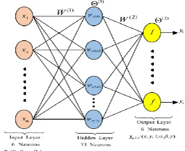
Convenient localization property in time domain, efficient ability to approximate complicated mappings and impressive learning ability are the main characteristics of WNN make it appropriate and successful in approximation of nonlinear systems. Furthermore, to avoid the local minimum problem in training procedure of the NN the WNN is superseded to neural networks which follow the availability of the rates of the convergence for approximation by wavelet based networks. Proposed WNN is constructed by association of neurons in forward pathway. In current contribution, a feed forward MIMO-WNN is designed with three input-hidden-output layers using wavelets as the activate functions of the hidden layer. The proposed WNN consist of m, p and n nodes in the input, hidden and output layers, respectively. The number p is defined by the minimum prediction risk principle with using final prediction error (FPE). Figure 2 illustrates the topology of the proposed WNN with the activate function of thejth node in the hidden layer as:
p j a b t a t j j j b
aj j ( ) 1,2,...,
1 ) ( , (13)
where, (t) is the wavelet function and chosen Morlet wavelet function and f(t) is considered sigmoid function.
4. 2. Training Algorithm For training a feed forward networks the back propagation (BP) algorithm is the most useful and applicable [18, 19] and it is employed to train the proposed WNN. BP includes forward and backward passes. The output performance of the network is provided by the forward pass and the backward pass specifies the initial errors for each node of the network. So, for minimizing all specified errors the weights of the network are regulated. Since the input vector X(x1,x2,...,xm) is feed to the proposed WNN in Figure 2; the output of the th
j node in hidden layer is
defined as: ) ( 1 ) ( ) ( ) 1 ( ) 1 ( , 1 ) 1 ( ) 1 ( , j j j j j b a m k j k jk b a a b F a F x
w j j
j j
(14) ) ( 1 ) 1 ( ) 1 ( ) 1 (
m k j k jkj w x
F (15)
The ith node of output layer yields to:
) ( ) ) (
( , (1) (2) (2)
1 ) 2 ( i i j bj aj p j ij
i f w F f F
y
(16) ) ) (
( , (1) (2)
1 ) 2 ( ) 2 ( i j bj aj p j ij
i w F
F
(17)
) ,..., , (y1 y2 yn
Y is determined as the output vector of the WNN by Equation (16). Therefore, the total error for the network should be minimized is considered as follows:
Q q n i qi qi Y Y E 1 1 2 ) ( 2 1 (18)In which, Q is training samples, Yq(yq1,yq2,...,yqn) and
) ,..., ,
( q1 q2 qn
q y y y
Y are the desired and trained WNN
output vectors, respectively. For minimizing
E
, the iterative gradient descent method is employed to formulate the WNN parameters as follows:j j j j j j j j j j j j i i i i jk jk jk jk ij ij ij ij b E t b t b t b a E t a t a t a E t t t E t t t w E t w t w t w w E t w t w t w ) 1 ( ) ( ) 1 ( ) 1 ( ) 1 ( ) ( ) 1 ( ) 1 ( ) 1 ( ) ( ) 1 ( ) 1 ( ) 1 ( ) ( ) 1 ( ) 1 ( ) 1 ( ) ( ) 1 ( ) 1 ( ) 1 ( ) ( ) 1 ( ) 1 ( ) 1 ( ) 1 ( ) 1 ( ) 1 ( ) 2 ( ) 2 ( ) 2 ( ) 2 ( ) 1 ( ) 1 ( ) 1 ( ) 1 ( ) 2 ( ) 2 ( ) 2 ( ) 2 ( ) (19)
In which,
t
and the are learning iteration index and the rate of learning, respectively. Also, is the momentum factor and considered 01 to improve the rate of learning. The partial derivatives of the errorE
respect to each parameter can be calculated easily.4. 3. Optimum Topology for WNN Identification the optimum topology and correct construction of the network is most important steps in NN simulation which is included the number of hidden layers and the number of neurons in the hidden layers.
Networks with more or fewer hidden units than needed, result in over-fitted model or poor learning the underlying function, respectively. In current paper, we utilized the minimum prediction risk principle with using final prediction error (FPE) [20] to find the best and optimum topology of our proposed WNN.The prediction risk P measures the generalization ability of network and is defined as below for network:
2 2
* * 2
1 ˆ
( )[ ( ) ( )]
1 ˆ
( )
n
p p
p
P dx p x x x
E y y
n
(20)where, (x) is an unknown function, p(x)is stationary probability density function, is the variance of independent random variables. Also, (x*p,y*p) are the new observations that were not used in the construction of the network and yˆ*p is the network output forx*p. Since finding the prediction risk is not a straight forward procedure, we used (FPE) criterion as reported in literture [20]:
n
p
p p y y k n
n k
P
1
2 * *
) ˆ ( 2 2
1
(21)
where, k is the number of parameters of the network and nis the number of training patterns in the training sample. The target value is given byyp, and yˆ the p
approximation of the target value by the network. To find the optimum topology of WNN the algorithm is followed as below. At first a WNN without any hidden unit is constructed. So, the network is trained and then the prediction risk is estimated by FPE. Next, 1 hidden unit is added to hidden layer and the network training and prediction risk estimation is repeated. We continued the procedure by adding hidden unit and repeating network training and prediction risk estimation until we reach to the predefined maximum number of hidden units. The number of hidden units relevant to smallest prediction risk define the optimum number of wavelets for the best topology of network.
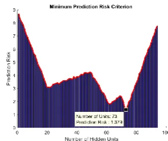
The algorithm is illustrated in Figure 3. Also, Figure 4 shows the prediction risk versus number of hidden units for our proposed WNN. As it is clear, the optimum number occurred in 73 units with 1.379 prediction risk.
5. WNN SOLUTION FOR FKP
In order to solve the FKP of 6-RSU mechanism by means of WNN, the rotation angles of revolute joints in joint-space,X(
1,
2,...,
6) are considered as inputdata and Along with the training samples are feed to the network for process training procedure.
To approximate the kinematics model of the 6-RSU mechanism, the algorithm of wavelet neural network is summarized in 5 steps.
Step 1: Set the initial values of the momentum factor, rate of learning and the parameters of network
) ( , , , , 1,..., , 1,...,
) 2 ( ) 1 ( ) 2 ( ) 1 (
p
p b b
a a W
W .
Step 2: Give the input vectorsX(
1,
2,...,
6) and desired output vector Yq (xq,yq,zq,
q,
q,
q) as the training data to handle the training of network. The exact theoretical values of training data were obtained by inverse kinematic solution from Equation (8).Step 3: Estimate the output of the WNN by Equation (16) for each input data.
Step 4: Regulate the networks parameters employing gradient descent algorithm by Equation (19).
Step 5: The total error of the proposed network is estimated by Equation (18).
Figure 3. Optimum Topology Selection Algorithm by Using FPE
If the error is in the desired range, the networks parameters are determined and the learning process is completed, else restart the learning procedure.
6. SUMULATION AND RESULTS
The results of the proposed WNN on approximating the forward kinematic analysis of the 6-RSU mechanism are presented in this section. The proposed structure for designed wavelet network has one input layer with six neurons, one hidden layer with 73 neurons and one output layer with six neurons. The network was trained with a learning rate of 0.21, a momentum term of 0.55, and 1024 learning iterations. The largest error E or given precision is less than 0.6%. First, using inverse kinematic solution for the Hexarot, the closed form solution (CFS) were obtained for two different paths (paths I and II). Data extracted by path (I) is feed to train the network. Besides, to verify the performance of network after training, path (II) is applied. Figures 5 to 10 show the results of the proposed WNN using the path (I) for simulation.
Using the inverse kinematic analysis for proposed paths, the motions of the each upper arm is defined. Then, the proposed WNN is feed by the arms motions to get the trajectory and movement paths of the manipulated platform. Again, the outputs of the proposed WNN are employed for inverse kinematic analysis to define the new motions of the arms and to the comparison with those obtained by CFS.
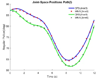
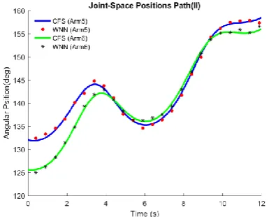
Figures 5 to 7 show the results for joint-space and angular position for all six arms During Path (I). Figures 8 and 9 indicate the results for position and orientation of manipulated platform, respectively. Also, the results displayed in Figure 10 show the position of manipulated platforms in 3D view. These results are employed to train the WNN. However, verification of the proposed WNN is executed by path (II). The results are illustrated in Figures 11 to 16. Figures 11 to 13 present the comparison of the results between WNN and CFS for the movments of the arms in joint space during path (II). Figures 14, 15 and 16 illustrate the CFS and WNN results in work-space included position, orientation and spatial displacement for the manipulated platform.
According to the results illustrated in Figures 5 to 16 there is good agreement between the exact solution (CFS) and the outputs of proposed WNN. The errors are less than %1 and it demonstrates the efficiency and superiorityof the WNN as a powerful method to approximate the highly nonlinear dynamic systems.
Figure 5. Results for Joint-Space kinematic parameters During Path (I) – Angular Position for Arms 1 and 2
Figure 6. Results for Joint-Space kinematic parameters During Path (I) – Angular Position for Arms 3 and 4
Figure 8. Results for Work-Space kinematic parameters During Path (I) – Position of Manuplated Platform
Figure 9. Results for Work-Space kinematic parameters During Path (I) – Orientation of Manuplated Platform
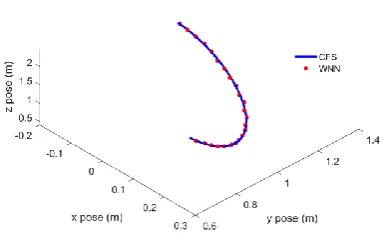
Figure 10. 3D Plot for Position Results of Manuplated Platform During Path (I) by CFS and WNN
Figure 11. Results for Joint-Space kinematic parameters During Path (II) – Angular Position for Arms 1 and 2
Figure 12. Results for Joint-Space kinematic parameters During Path (II) – Angular Position for Arms 3 and 4
Figure 14. Results for Work-Space kinematic parameters During Path (I) – Position of Manuplated Platform
Figure 15. Results for Work-Space kinematic parameters During Path (II) – Orientation of Manuplated Platform
Figure 16. 3D Plot for Position Results of Manuplated Platform During Path (II) by CFS and WNN
To estimate the training and computing time for proposed WNN, the “tic” and “toc” functions were used in the code written in MATLAB. The training time for 1024 learning iteration is 20.68 (s) and the computing time for simulation after training the network is less
than 0.2 (s). So, the proposed WNN can be employed to practical applications.
7. CONCLUSIONS
The main goal of the current contribution is the application of wavelet neural network as a useful tool to solve the forward kinematics problem of the Hexarot. To this end, using the vectorial and geometrical principles, the kinematic model of the mechanism is obtained and the inverse kinematic problem is solved. Due to the difficulty of the forward kinematic analysis of the parallel mechanisms and the serious impediments of the classical numerical algorithms, neural network analysis based on wavelet functions is proposed. Therefore, the invers kinematic analysis is employed to provide data for network training and verification. Back propagation algorithm and the iterative gradient descent method are used to minimize the total error of the network and to formulate the WNN parameters. The minimum prediction risk principle with using final prediction error are utilized to find the best and optimum topology of our proposed WNN. The proposed WNN are exerted to the deferent paths and the accurate results are generated. According to training approach of the network the maximum error is less than 0.6%. So, the comparison of the results obtained by WNN with the CFS indicates the accurate performance and the superiority of the proposed neural network algorithm.
8. REFERENCES
1. Isaksson, M., Gosselin, C. and Marlow, K., "Singularity analysis of a class of kinematically redundant parallel schönflies motion generators", Mechanism and Machine Theory, Vol. 112, (2017), 172-191.
2. Li, T., Li, F., Jiang, Y., Zhang, J. and Wang, H., "Kinematic calibration of a 3-p (pa) s parallel-type spindle head considering the thermal error", Mechatronics, Vol. 43, (2017), 86-98. 3. Mohan, S., "Error analysis and control scheme for the error
correction in trajectory-tracking of a planar 2prp-ppr parallel manipulator", Mechatronics, Vol. 46, (2017), 70-83.
4. Pedrammehr, S., Danaei, B., Abdi, H., Masouleh, M.T. and Nahavandi, S., "Dynamic analysis of hexarot: Axis-symmetric parallel manipulator", Robotica, Vol. 36, No. 2, (2017), 225-240.
5. Schreiber, L.-T. and Gosselin, C., "Kinematically redundant planar parallel mechanisms: Kinematics, workspace and trajectory planning", Mechanism and Machine Theory, Vol. 119, (2018), 91-105.
6. Herrero, S., Pinto, C., Altuzarra, O. and Diez, M., "Analysis of the 2pru-1prs 3dof parallel manipulator: Kinematics, singularities and dynamics", Robotics and Computer-Integrated Manufacturing, Vol. 51, (2018), 63-72.
Engineering Transactions C: Aspects, Vol. 30, No. 9, (2017), 319-1325.
8. Xu, Q., Yang, Y., Jing, Z. and Hu, S., "Forward kinematics analysis for a class of asymmetrical parallel manipulators", International Journal of Advanced Robotic Systems, Vol. 14, No. 1, (2017), 1729881416678132.
9. Huang, G., Guo, S., Zhang, D., Qu, H. and Tang, H., "Kinematic analysis and multi-objective optimization of a new reconfigurable parallel mechanism with high stiffness", Robotica, Vol. 36, No. 2, (2017), 187-203.
10. Gao, L. and Wu, W., "Forward kinematics modeling of spatial parallel linkage mechanisms based on constraint equations and the numerical solving method", Robotica, Vol. 35, No. 2, (2017), 293-309.
11. Sadjadian, H., Taghirad, H. and Fatehi, A., "Neural networks approaches for computing the forward kinematics of a redundant parallel manipulator", International Journal of Computational Intelligence, Vol. 2, No. 1, (2005), 40-47.
12. Rahmani, A. and Ghanbari, A., "Application of neural network training in forward kinematics simulation for a novel modular hybrid manipulator with experimental validation", Intelligent Service Robotics, Vol. 9, No. 1, (2016), 79-91.
13. Lu, Y., Wang, P., Zhao, S., Hu, B., Han, J. and Sui, C., "Kinematics and statics analysis of a novel 5-dof parallel manipulator with two composite rotational/linear active legs", Robotics and Computer-Integrated Manufacturing, Vol. 30, No. 1, (2014), 25-33.
14. Qazani, M.R.C., Pedrammehr, S., Rahmani, A., Danaei, B., Ettefagh, M.M., Rajab, A.K.S. and Abdi, H., "Kinematic analysis and workspace determination of hexarot-a novel 6-dof parallel manipulator with a rotation-symmetric arm system", Robotica, Vol. 33, No. 08, (2015), 1686-1703.
15. Qazani, M.R.C., Pedrammehr, S., Rahmani, A., Shahryari, M., Rajab, A.K.S. and Ettefagh, M.M., "An experimental study on motion error of hexarot parallel manipulator", The International Journal of Advanced Manufacturing Technology, Vol. 72, No. 9-12, (2014), 1361-1376.
16. Bazoobandi, H., "Wavelet neural network with random wavelet function parameters", International Journal of Engineering-Transactions A: Basics, Vol. 30, No. 10, (2017), 1510-1516. 17. Hashemi, S.M.A., Haji Kazemi, H. and Karamodin, A.,
"Verification of an evolutionary-based wavelet neural network model for nonlinear function approximation", International Journal of Engineering, Vol. 28, No. 10, (2015), 1423-1429. 18. Huang, M. and Cui, B., "A novel learning algorithm for wavelet
neural networks", ICNC 2005: Advances in Natural Computation, Springer-Verlag Berlin Heidelberg, (2005), 421-421.
19. Neshat, N., "An approach of artificial neural networks modeling based on fuzzy regression for forecasting purposes", International Journal of Engineering-Transactions B: Applications, Vol. 28, No. 11, (2015), 1651-1655.
20. Moody, J., Prediction risk and architecture selection for neural networks, in From statistics to neural networks. 1994, Springer.147-165.
Application of Wavelet Neural Network in Forward Kinematics Solution of 6-RSU
Co-axial Parallel Mechanism Based on Final Prediction Error
A. Rahmani
Faculty of Mechanical Engineering, Urmia University of Technology, Urmia, Iran
P A P E R I N F O
Paper history: Received 17 January 2018
Received in revised form 27 February 2018 Accepted 09March 2018
Keywords:
Wavelet Neural Network Kinematic Analysis 6-RSU Parallel Mechanism Final Prediction Error
هديكچ
مانب دیدج یزاوم مزیناکم کی ادتبا هلاقم نیا رد
HEXAROT
یاا ی یاراد یزاوام یااا مزینااکم ریاس اب هسیاقم رد هک
مزیناکم نیا .دوش یم ییرعم ،تسا یرتشیب بتارم هب یراک
6
هاب هآ یکیتاینیاس راتاااس هاب هجوت اب و هدوب یدازآ هجرد
مزیناکم
6-RSU
مزینااکم یکیتاینیاس لدم هژویا سیرتام شور و اارادرب ربج زا هدافتسا اب سپس .دشاب یم فورعم زین
هاکییاجنآ زا .دواش یام ماجنا هکبش شزومآ یارب مزلا یاااتید دیلوت تهج هب مزیناکم سوکعم کیتاینیس لح و جارختسا زا یشان هک روکذم مزیناکم یکیتاینیس لدم هدوب هدیچیپ لیلدب تاباساحم ،تسا یکیتاینیس تلاداعم دیدش هدوب یطاریغ
تلویو یبصع هکبش لدم ورنیا زا تسا نکیم ریغ لایع میقتسم کیتاینیس لح هب طوبرم
(WNN)
کیتاینیاس لح تهج
.تسا هدیدرگ یراذگ هحص سوکعم کیتاینیس زا لصاح جیاتن اب هآ زا هدمآ تسدب جیاتن و هدش هدافتسا و یحارط میقتسم ش لدم تالرام یزااسلاعی یااا هوران ااب هایلا هاس هکباش کای هلاقم نیا رد هدش هیارا یعونصم یبصع هکب
(Morlet)
و
دییویگیس
(Sigmoied)
ل اداح شور زا هدافتاسا ااب هآ یاراب هانیهب یژولوپوت هک تسا یجورا و ینایم یاا هیلا یارب
ینیب شیپ کسیر
(MPR)
ییاهن یاطا ینیب شیپ و
(FPE)
یسررب و یزاس هیبش تهج هلاقم نیا رد .تسا هدمآ تسد هب
ریاسم .تاسا هدش هتیرگ رظن رد یطاریغ هدیچیپ تلاداعم اب ریسم ود هدش یحارط یبصع هکبش درکلیع
I
دایلوت تاهج
ریسم و هکبش شزومآ یارب اااتید
II
تاسدب جیاتن هسیاقم .تسا هدش هدافتسا هدش هداد شزومآ هکبش یراذگ هحص تهج
مآ .دشاب یم هدش یحارط یبصع هکبش یدمآراک و ت د رگنایب قی د لح زا لصاح جیاتن اب یبصع هکبش زا هد