Iranian Journal of Electrical & Electronic Engineering, Vol. 14, No. 1, March 2018 59
A New Pulsating Power Elimination Method for Single-Phase
PWM AC/DC Converters with Minimum Voltage and
Current Stress
H. Rezaie*(C.A.), H. Rastegar* and M. Pichan*
Abstract: An inherent problem of single-phase rectifiers is the existence of a pulsating portion in the input power, which pulsates at twice the grid frequency. If this pulsating power is transferred to the DC-link, it causes a significant amount of second-order harmonic at the output voltage. Since in many applications, such a high level of DC oscillation is not acceptable, so the pulsating power must be effectively filtered. A convenient solution to eliminate the output voltage oscillations is to use a capacitor with a relatively high capacity at the rectifier output. Due to the fact that the high capacity capacitors for this application usually have a short lifetime and occupy a lot of space, this solution cannot be considered as a proper one. In this paper, a new active method with the minimum of current and voltage stress is proposed to effectively eliminate the pulsating power and significantly reduce the required capacitance of the output filter. The proposed method is able to reduce the volume of the converter and increase its reliability and power density. The validity and effectiveness of the proposed method are confirmed by extensive simulations in the MATLAB/Simulink.
Keywords: Single Phase Systems, Single Phase PWM Rectifier, Active Power Decoupling,
Active Filter, Pulsating Power, Capacitance Reduction, Current Stress, Voltage Stress.
1 Introduction1
INGLE-PHASE AC/DC or DC/AC power converters are widely used in residential and industrial applications [1]. However, an inherent problem of these conversion systems is the pulsating power with twice the grid frequency at AC-side. This pulsating power should be filtered effectively in several applications, otherwise, it will degrade the system performance. For example, in LED lighting applications, it leads to light flicker [2,3] which can be harmful to human’s eyesight, in battery chargers application, it causes overheating and reducing the battery lifetime [4], in conversion systems for PV panels
Iranian Journal of Electrical & Electronic Engineering, 2018. Paper first received 10 October 2017 and accepted 20 January 2018. * The authors are with the Department of Electrical Engineering, Amirkabir University of Technology (AUT), Tehran, Iran.
E-mails: [email protected], [email protected] and [email protected].
Corresponding Author: H. Rezaie.
and fuel cells, it leads to reduce the maximum power point tracking (MPPT) efficiency of PV systems [5] and the lifetime of fuel cells [6,7].
A conventional method for eliminating the pulsating power is the use of a high-capacitance capacitor at the DC-side [8]. However, since the capacitors that are appropriate for this purpose are usually Electrolytic Capacitors (E-Caps) which have a short lifetime and a large size, this solution reduces the reliability and power density of the system [9]. To solve this problem, several active power decoupling methods have been proposed to reduce the DC-link capacitance requirement in single-phase converters [10]. The main idea used in these methods is absorbing the pulsating power by auxiliary energy storage elements (capacitor or inductor), so that a low-capacitance capacitor with a low size and a long lifetime, like film-capacitor, can be used at the DC-side instead of a bulky E-cap with a short lifetime, which makes the converter more reliable and compact.
In the following, some of the active methods presented in the previous works are mentioned.
S
Iranian Journal of Electrical & Electronic Engineering, Vol. 14, No. 1, March 2018 60 In [11,12], the suggested rectifier topology has an
additional leg (including two switches with reverse-parallel diodes) which conducts the pulsating power into the auxiliary energy storage element and prevents it from being transmitted to the DC-link. Also, in [13], a similar structure is employed, however, the difference is that the additional leg only includes one switch in series with one diode. Although the number of elements is reduced in this work, this topology needs a more complicated controller since the reference current is rectified sinusoidal. In [14], a buck-boost converter, located between the rectifier main circuit and the output capacitor, is employed to filter the pulsating power, and in [15], a symmetrical half-bridge circuit, which can be added to the rectifier main circuit, is suggested to eliminate the pulsating power. It is worth mentioning that the auxiliary energy storage element, which absorbs the pulsating power, can be capacitive or inductive. As a comparison between capacitors and inductors, inductors are usually more reliable and robust, but capacitors have higher power density and lower power losses [15]. In this paper, a new active method to eliminate the pulsating power and reduce the DC-link capacitance requirement in single-phase rectifiers is proposed. In the suggested method, a capacitor is used to absorb the pulsating power, also an inductor is located in series with it to smooth its current, and an additional leg is used to conduct the pulsating power into the auxiliary energy storage elements. In the proposed method, the reference signals used in the third leg controller are sinusoidal and the third leg has its own separate controller, so there is no need to change the main control system of the rectifier, and the rectifier is able to work properly with and without applying the proposed method. Some of the advantages of the proposed method compared to the previous works are having the minimum of current and voltage stress and the less complexity of the control system which makes it simpler to implement.
The rest of this paper is organized as follow: single-phase PWM rectifier and its conventional control system are described in section 2. The proposed active method to eliminate the pulsating power is presented in section 3, and its effectiveness is investigated and verified by extensive simulations in MATLAB/Simulink in section 4.
2 Single Phase PWM Rectifier
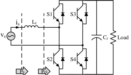
A typical topology of single phase PWM rectifier is presented in Fig. 1 [16]. In this topology, the input inductor is used to smooth the input current and decrease its total harmonic distortion (THD), and the output capacitor is used to even the output voltage and reduce its ripple.
Suppose that the AC source voltage is as follow: (1)
sin
s s
v t V t
where Vs and ω are the amplitude and angular frequency of the voltage source. Assuming the unity power factor operation, the input current can be expressed as Eq. (2).
(2)
sin
s s
i t I t
where Is is the amplitude of the source current. The instantaneous power of the source can be calculated from Eq. (3).
(3)
cos 2
2 2
s s s s
s s s
V I V I
P v t i t t
And the instantaneous power of Lf can be obtained using Eq. (4).
(4)
2
1
sin 2 2
f
s
L s f f s
di
P i L L I t
dt
where Lf is the inductance of the input inductor. So, the instantaneous input power of the converter can be expressed as follow:
(5)
f
ci s L
P P P
By substituting Eqs. (3), (4) in Eq. (5), Pci can be obtained as Eq. (6).
(6)
1 2
cos 2 sin 2
2 2 2
s s s s
ci f s
c f
V I V I
P t L I t
P P
According to Eq. (6), the input power of the converter consists of two parts; a constant part (Pc) and a pulsating part with twice the grid frequency (Pf), which should be effectively filtered, otherwise it will cause a significant amount of second-order harmonic at the output voltage which can have negative effects on the DC loads’ performance.
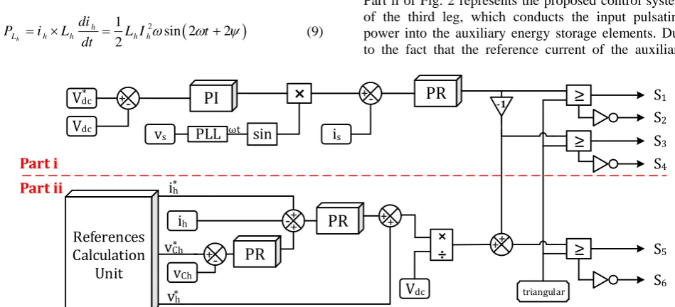
Fig. 2 part i shows a schematic diagram of the conventional control system of single phase PWM rectifiers [17]. The main tasks of this controller are DC voltage adjustment, providing unity power factor operation and input current with minimum THD. In this controller, there are two control loops:
Load S3
S4 S1
S2
v
si
s LfPs Pci
Cf
Fig. 1 A typical topology of single phase PWM rectifier.
Iranian Journal of Electrical & Electronic Engineering, Vol. 14, No. 1, March 2018 61 1. an outer loop voltage controller;
2. an inner loop current controller.
In the outer loop, the DC voltage’s error is regulated using a proportional-integral (PI) controller. Using a single-phase phase-locked loop (PLL), a unit amplitude signal synchronous with the source voltage is generated [18]. By multiplying the outputs of PI compensator and PLL, the reference source current is attained. In the inner loop, since the reference of the input current is an AC signal, a proportional-resonant (PR) controller is employed for current regulation [19]. Notice that in the control system presented in Fig. 2, the unipolar switching method is used to increase the effective switching frequency and reduce the DC voltage ripple [20].
3 Proposed Active Power Decoupling Method
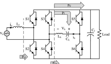
Fig. 3 presents the rectifier topology used in the proposed active power decoupling method. In this topology, the third leg is added to the main structure of the rectifier to conduct the fluctuating power to the auxiliary energy storage elements (Ch and Lh) and
prevents it from being transmitted to the DC link. So, the total instantaneous power of the auxiliary elements (Ph) should be equal to Pf.
(7)
h h
h C L f
P P P P
Considering that Pf pulsates at twice the grid frequency, to establish the above equation, the reference current of the auxiliary branch should be sinusoidal at the grid frequency as given in Eq. (8).
(8)
h h
h C L f
P P P P
The instantaneous power of Lh and Ch can be obtained
from the following equations.
(9)
2
1
sin 2 2 2
h
h
L h h h h
di
P i L L I t
dt
(10)
2
1 1
sin 2 2 2
h
C h h h
h h
P i i dt I t
C C
By substituting Eqs. (6), (9), (10) in Eq. (7), the following equation can be written.
(11)
2 2 2 1cos 2 sin 2
2 2
1 1
sin 2 2 sin 2 2
2 2
s s
f s
h h h
h
V I
t L I t
L I t I t
C
Using trigonometric relationships and some simplifications, Eq. (11) can be rewritten as:
(12)
2 2 2 2 sin 2 1sin 2 2
h
f s s s
h L
h
L I V I t
L I t
C in which (13) -1 tan s f s V L I
According to Eq. (13), the amplitude and phase of ih to filter the pulsating power can be obtained as presented in Eq. (14).
(14)
2
2
22
4 1
-2
s s f s
h
h h
V I L I
I L C
Part ii of Fig. 2 represents the proposed control system of the third leg, which conducts the input pulsating power into the auxiliary energy storage elements. Due to the fact that the reference current of the auxiliary
Vdc
Vdc
*
vs PLL
PI
+ -sin ωt
PR
+ -is References Calculation Unitih -++
vCh
+-
PR
PR
++÷
Vdc
++
ih*
vCh*
v*h triangular
S1 S2 S3 S4 S5 S6 -1 Part i Part ii
Fig. 2 The control system.
Iranian Journal of Electrical & Electronic Engineering, Vol. 14, No. 1, March 2018 62 elements has a sinusoidal waveform, a PR controller is
used for regulating the current and tracking its reference. Also, to improve the controller performance and accuracy, a supplementary control loop is included in the control system to adjust the auxiliary capacitor voltage. Since the reference voltage of the capacitor is also sinusoidal, again a PR controller is employed to adjust it. The sinusoidal reference waveforms provide a simpler control method compared to other methods in which the reference current or voltage of the auxiliary energy storage elements to eliminate the pulsating power has a non-sinusoidal reference signal [13]. Considering the relatively high switching frequency, the converter averaged model is applicable and the control signal for the switching of the third leg can be obtained from Eq. (15) [21].
(15)
h c b dc
V d d V
Equation (15) can be rewritten as:
(16) h c b dc V d d V
where db and dc are the duty ratio of S3 and S5, respectively. The control structure presented in part ii of Fig. 2 is based on Eq. (16) and the reference signals can be calculated based on Eq. (14). In this figure, vch and
v*
ch are the actual voltage and reference voltage of the auxiliary capacitor (Ch), respectively, and v*h is the reference voltage of the auxiliary branch which can be calculated by the following equation:
(17)
* * *
cos
h h
h C L
h
h h h
h h h h
V V V
di
L C i dt
dt C I
L I t
3.1 Sensitivity Analysis of the Auxiliary Branch Current Amplitude to the Values of Auxiliary Elements
According to Eq. (14), the current amplitude of
S5 Load S6 S3 S4 S1 S2 vs
is Lf
Pci
Pf
Cf
Lh
Ch ih
Vh +
_
Fig. 3 The rectifier topology used in the proposed active
method.
auxiliary branch can be considered as a function of the auxiliary capacitance and inductance, assuming that the rest of the parameters are constant.
(18)
1
2 ,
h h h
I ku C L
in which
(19)
1,
-h h h
h
u C L L
C
(20)
2
2
24
s s f s
k= V I + L ωI
By deriving from Eq. (18), once with respect to Ch, and
once with respect to Lh, the following equations can be
written. (21)
3 2 3 2 2 2 1 2 h h h h h h h hI f C
I k u
u C C k L C C (22)
3 2 3 2 2 1 2 h h h h h h hI f L
I k u
u
L L
k
L
C
By dividing Eq. (21) to Eq. (22), Eq. (23) will be obtained. (23)
2 2 1 -h h h h h h I C C I C L According to Eq. (23), the ratio of the reference current sensitivity against capacitance variations to its sensitivity against inductance variations varies from infinite to 40.5285 for capacitance changing from 0 to 500µF. In other words, by increasing of the capacitance, the sensitivity of the reference current to the inductance variations will be increased. However, for the highest determined value of capacitance, the current sensitivity to the inductance is still much less than its sensitivity to the capacitance. Therefore, the capacitance is the main parameter that specifies the reference current amplitude and the inductance value should be determined by trading off between current smoothing and system volume. Also, to more elucidate the amount of current sensitivity to the value of the auxiliary elements, the
Iranian Journal of Electrical & Electronic Engineering, Vol. 14, No. 1, March 2018 63 amplitude variations of the reference current for
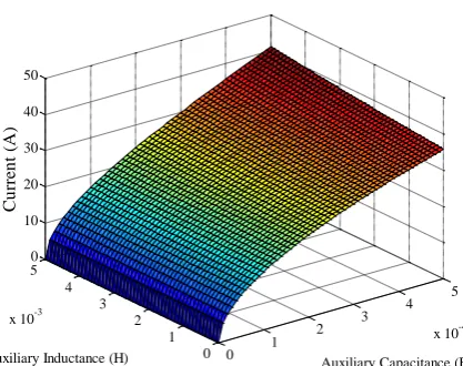
variations of the auxiliary capacitance and inductance is presented in Fig. 4. In this figure, other systems parameters to calculate the amplitude of the reference current are chosen as what is given in section 4, Table 1. As proved through Eq. (23) and according to Fig. 4, the main parameter that determines the amplitude of the reference current is the auxiliary capacitance.
3.2 Capacitance Calculation to Provide the Minimum Current Stress
Suppose the current amplitude of the auxiliary branch is equal to input current:
(24)
h s
I I
So, Eq. (14) can be rewritten as Eq. (25)
(25)
2
2
24
2
1
s s f s
s
h h
V I L I
I L C
According to Eq. (6)
(26) 2 c s s P I V
By substituting Eq. (26) in Eq. (25), the following equation can be written.
(27)
2 2 2 2 4 4 2 2 1 4s s f s
h
h s
s f c
V I L I
L C I V L P
Then, the capacitance of Ch can be calculated as
Eq. (28)
0 1
2 3
4 5
x 10-4
0 1 2 3 4 5
x 10-3
0 10 20 30 40 50
Auxiliary Capacitance (F) Auxiliary Inductance (H)
Cu
rren
t
(A
)
Fig. 4 The reference current amplitude variations for
variations of the auxiliary capacitance and inductance.
(28)
2 2 2 1 2 h s f h c C V L L P Therefore, if the capacitance of Ch is chosen as Eq. (28),
the amplitude of the input current and current of the auxiliary branch will be equal to each other and current stress of the system will be minimized.
3.3 Voltage Stress Investigation
In Eq. (28), due to the fact that the inductances have a relatively small value (mH), the terms that include inductance have a much smaller value compared to
Vs2/ 2Pc
, so they can be ignored.(29) 2 2 c h s P C V
The voltage of the auxiliary branch can be calculated from Eq. (30)
(30) 1
h h
h
h L C h h
h
di
v v v L i dt
dt C
By substituting Eq. (8) in Eq. (30), Eq. (31) will be achieved.
(31)
cos( ) cos
1
- cos
h
h h h
h
h h
h
I
v L I t t
C
L I t
C
So, the voltage amplitude of the auxiliary branch is equal to:
(32)
h
h h h
h
I
V L I
C
Again, by ignoring the term that includes inductance, the voltage amplitude will be approximately equal to:
(33) s h h I V C
By substituting Eqs. (26), (29) in Eq. (33), Eq. (34) will be obtained, which indicates that in the proposed method, minimization of the current stress will also lead to minimize the voltage stress.
(34) 2 2 2 c s h s c s P V V V P V
Iranian Journal of Electrical & Electronic Engineering, Vol. 14, No. 1, March 2018 64
4 Simulation Results
In this section, by using converter simulation in MATLAB/Simulink, first the performance of single phase PWM rectifier with the conventional control system has been studied, and then the effectiveness of the proposed method in eliminating the input pulsating power and decreasing the required capacitance at the DC-side has been investigated and finally a comparison between the proposed method and one of the most outstanding methods presented in this field has been presented. The parameters’ value used in the simulation of the single phase rectifier is given in Table 1.
4.1 Simulation of the Rectifier with the Conventional Controller
Fig. 5 shows the output voltage of the rectifier with the large output capacitor and Fig. 6 shows its input voltage and current, simultaneously. According to Fig. 5, the controller has suitable performance in adjusting the output voltage and the amount of output ripple is almost 12V (2.67%). According to Fig. 6, the
controller also has suitable performance in providing unity power factor operation and input current with a low THD value. Using FFT analysis tool in MATLAB, the THD value in this case, is calculated as 4.24% which is an acceptable value according to international standards.
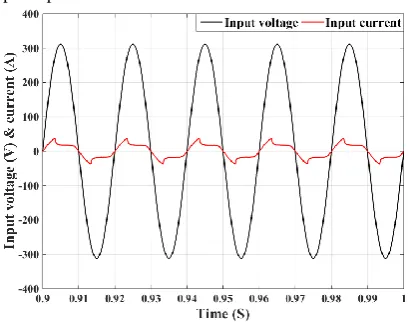
Fig. 7 presents the output voltage of the rectifier with the small output capacitor and Fig. 8 presents its input voltage and current, simultaneously. According to Fig. 7, the controller has been able to approximately adjust the average output voltage to its reference, however, Due to the small capacitance at the DC-side, it is not able to effectively reduce the output fluctuations. The amount of output ripple is almost 224V (49.78%) which is an unacceptably high value and interferes with other controller tasks as well. According to Fig. 8, the controller again has proper performance in providing unity power factor operation, but due to the high fluctuations of the output voltage, it is unable to provide the input current with a low THD value. The THD value in this case, is calculated as 34.06% which is not an acceptable value.
Table 1 The parameters’ value used in the system simulation.
Parameter Vs f Vdc Pn Lf Cf (small) Cf (large) fsw
Value 220 Vrms 50 Hz 450 V 4 kW 3 mH 100 µF 2400 µF 10 kHz
Fig. 5 The output voltage of rectifier with the large output
capacitor.
Fig. 6 The input voltage and current of rectifier with the large
output capacitor.
Fig. 7 The output voltage of rectifier with the small output
capacitor.
Fig. 8 The input voltage and current of rectifier with the small
output capacitor.
Iranian Journal of Electrical & Electronic Engineering, Vol. 14, No. 1, March 2018 65
4.2 Simulation of the Rectifier with the Proposed Method
In this section, the effectiveness of the proposed method is investigated. The auxiliary inductance Lh is
chosen as 0.8mH and the auxiliary capacitance Ch
according to Eq. (28) is chosen as 256.95µF to provide minimum current and voltage stress.
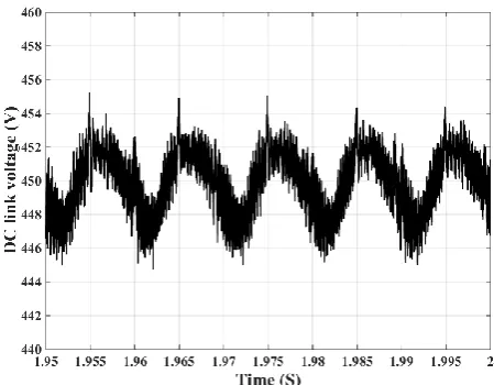
Fig. 9 shows the output voltage of the rectifier with the proposed method and small output capacitor. According to Fig. 9, the proposed controller has suitable performance in adjusting the output voltage and the amount of output ripple is almost 10V (2.22%). This value is approximately equivalent to the amount of output ripple of the rectifier with a 2900µF capacitance at the output, without applying the proposed method. It means that in this case, the proposed method is able to reduce the required output capacitance of the rectifier by 96.55% (a ratio of 28/29). Also, in order to better compare, the output voltage of the rectifier with and without applying the proposed method, with the small output capacitor is presented in Fig. 10.
Fig. 11 shows the input voltage and current of the rectifier, simultaneously. According to this figure, the controller has suitable performance in providing unity power factor operation and input current with a low THD value. Using FFT analysis tool in MATLAB, the THD value in this case, is calculated as 2.96% which is an acceptable value according to international standards. Notice that this value is even lower than the current THD of the rectifier with a 2400 µF output capacitive filter without applying the proposed method (4.24%), so the third leg and its controller not only does not cause any problem in the performance of the main controller, but also can improve its performance.
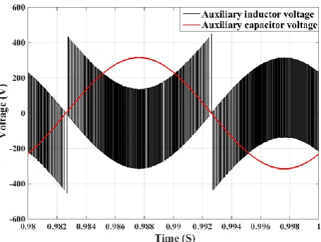
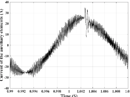
The input current and reference current of the auxiliary branch, and the input voltage and reference voltage of the auxiliary branch in the proposed method are shown in Figs. 12 and 13, respectively. Also, the actual voltage of the auxiliary energy storage elements is illustrated in Fig. 14. Based on Figs. 12 and 13, the amplitude of reference current of the auxiliary branch in the proposed method is equal to the amplitude of input current of the converter, and the amplitude of reference voltage is almost equal to the amplitude of input voltage of the converter. Therefore, the current and voltage applied to all switches are equal to each other and the converter has the least stress of the current and voltage. This point can be considered as one the most outstanding advantages of the proposed method compared to other introduced active power decoupling methods since to the best knowledge of the author, so far, there is only one proposed method in this area [22] which have the minimum of voltage and current stress. To observe the function of the controller designed to regulate the current of the auxiliary branch, the reference current and actual current of the auxiliary branch are shown in Fig. 15. Based on this figure, the
controller correctly follows the reference signal which leads to the efficient absorption of the fluctuating power by the auxiliary energy storage elements.
Fig. 9 The output voltage of rectifier with the proposed
method and small output capacitor.
Fig. 10 The output voltage of rectifier with the small output
capacitor, with and without the proposed method.
Fig. 11 The input voltage and current of rectifier with the
proposed method and small output capacitor.
Iranian Journal of Electrical & Electronic Engineering, Vol. 14, No. 1, March 2018 66 A proper control system must be robust against
system changes and has a suitable dynamic against the exerted variations. The most likely functional change that can occur to rectifiers is the change in the output power (load power consumption) because it is not necessary that the rectifier’s load be always at its nominal value, and depending on the different conditions, it can receive different currents (or powers) from the converter. In order to investigate the proposed controller performance against the load variations, Fig. 16 shows the output voltage of the rectifier, while the load current has been suddenly decreased from 1pu to 0.7pu at 1 sec. and it has been suddenly increased to its nominal value at 2 sec. Also, the current variations of the auxiliary branch in this case, and its zoomed figure are presented in Figs. 17 and 18, respectively. According to these figures, the rectifier with the proposed method has a satisfactory dynamic response to the sudden load changes and is able to adjust precisely the output voltage according to its reference with a suitable transient state.
Among the previous works presented in the field of eliminating the input pulsating power in single-phase PWM rectifiers, the method presented in [12] is one the most outstanding, and the used topology and the values of input and output voltage, grid frequency and rated power considered in that, are same as this paper. According to the simulation results reported in [12], the achieved output voltage ripple (peak-to-peak) is 9V (2%) which is a bit smaller than its value in this paper (10V-2.2%). In [12], the values selected for Lf, Cf, Lh,
and Ch are 8.5mH, 220µF, 1.85mH and 220µF,
respectively. These values are significantly higher than the used values in this work, with the exception of Ch
value. As mentioned before, the value of Ch in this work
is chosen so that it can provide the minimum current and voltage stress; the advantage that the suggested method in [12] does not have. Another important advantage of the proposed method compared to [12] is that the control system designed in this work has much less complexity which makes it much simpler to implement.
Fig. 12 The input current and reference current of the auxiliary
branch in the proposed method.
Fig. 13 The input voltage and reference voltage of the auxiliary
branch in the proposed method.
Fig. 14 The actual voltage of the auxiliary energy storage
elements.
Fig. 15 The reference current and actual current of the auxiliary
branch in the proposed method.
Iranian Journal of Electrical & Electronic Engineering, Vol. 14, No. 1, March 2018 67
Fig. 16 The output voltage of rectifier with the proposed
method and small output capacitor for load variations.
Fig. 17 The current of the auxiliary branch for load variations.
Fig. 18 The zoomed current of the auxiliary branch for load
variations.
5 Conclusion
This paper proposed an innovative active method to eliminate the pulsating portion of the input power of single-phase PWM rectifiers to prevent the emergence of a significant amount of the second-order voltage
harmonic in the converter output and consequently decrease the required capacitance of output filter by which the proposed method is able to reduce the converter volume and increase its power density. Also, due to the fact that the high-capacity capacitors for this application often have a relatively short lifetime, the proposed method, by reducing the required capacitance, makes it possible to use a low-capacitance capacitor with a long lifetime, like Film-capacitor, which makes the converter more reliable. Having the minimum of current and voltage stress and relatively less complicated control system are some of the advantages of the proposed method compared to other existing active methods in this area. The effectiveness of the proposed method evaluated and confirmed by system simulation in the MATLAB/Simulink.
References
[1] B. Singh, B. N. Singh, A. Chandra, K. Al-Haddad, A. Pandey, and D. P. Kothari, “A review of single-phase improved power quality AC-DC converters,”
IEEE Transactions on Industrial Electronics, Vol. 50, No. 5, pp. 962–981, Oct. 2003.
[2] S. Li, S. C. Tan, C. Lee, E. Waffenschmidt, S. Y. R. Hui, and C. K. Tse, “A survey, classification and critical review of light-emitting diode drivers,” IEEE Transactions on Power Electronics, Vol. 31, No. 2, pp. 1503–1516, Feb. 2016.
[3] W. Chen and S. Y. R. Hui, “Elimination of an electrolytic capacitor in AC/DC light-emitting diode (LED) driver with high input power factor and constant output current,” IEEE Transactions on Power Electronics, Vol. 27, No. 3, pp. 1598–1607, Mar. 2012.
[4] H. Kim and K. Shin, “DESA: dependable, efficient, scalable architecture for management of large-scale batteries,” IEEE Transactions on Industrial Informatics, Vol. 8, No. 2, pp. 406–417, May 2012. [5] H. Hu, S. Harb, N. Kutkut, L. Batarseh, and
Z. J. Shen, “A review of power decoupling techniques for microinverters with three different decoupling capacitor locations in PV systems,”
IEEE Transactions on Power Electronics, Vol. 28, No. 6, pp. 2711–2726, Jun. 2013.
[6] G. Fontes, C. Turpin, S. Astier, and T. A. Meynard, “Interactions between fuel cells and power converters: influence of current harmonics on a fuel cell stack,” IEEE Transactions on Power Electronics, Vol. 22, No. 2, pp. 670–678, Mar. 2007. [7] R. S. Gemmen, “Analysis for the effect of inverter ripple current on fuel cell operating condition,”
Journal of Fluids Engineering, Vol. 125, No. 3, pp. 576–585, May 2003.
Iranian Journal of Electrical & Electronic Engineering, Vol. 14, No. 1, March 2018 68 [8] H. Rezaie, H. Rastegar, and M. Pichan, “A new
active power decoupling method for single phase PWM rectifiers,” in 23rd Iranian Conference on
Electrical Engineering (ICEE), pp. 1665–1670, IEEE, 2015.
[9] H. Wang and F. Blaabjerg, “Reliability of capacitors for DC-link applications in power electronic converters—an overview,” IEEE Transactions on Industry Applications, Vol. 50, No. 5, pp. 3569–3578, 2014.
[10]P. T. Krein, R. S. Balog, and M. Mirjafari, “Minimum energy and capacitance requirements for single-phase inverters and rectifiers using a ripple port,” IEEE Transactions on Power Electronics, Vol. 27, No. 11, pp. 4690–4698, Nov, 2012.
[11]R. Wang, F. Wang, D. Boroyevich, R. Burgos, R. Lai, P. Ning, and K. Rajashekara, “A high power density single-phase PWM rectifier with active ripple energy storage,” IEEE Transactions on Power Electronics, Vol. 26, No. 5, pp. 1430-1443, May 2011.
[12]H. Li, K. Zhang, H. Zhao, S. Fan, and J. Xiong, “Active power decoupling for high-power single-phase PWM rectifiers,” IEEE Transactions on Power Electronics, Vol. 28, No. 3, pp. 1308–1319, Mar. 2013.
[13]M. Su, P. Pan, X. Long, Y. Sun, and J. Yang, “An active power-decoupling method for single-phase AC-DC converters,” IEEE Transactions on Industrial Informatics, Vol. 10, No. 1, pp. 461–468, Feb. 2014.
[14]Q. C. Zhong, W. L. Ming, X. Cao, and M. Krstic, “Reduction of DC-bus voltage ripples and capacitors for single-phase PWM-controlled rectifiers,” in
Proceedings IEEE IECON, Montreal, QC, pp. 1308-1313, 2012.
[15]Y. Tang, F. Blaabjerg, P. C. Loh, C. Jin, and P. Wang, “Decoupling of fluctuating power in single-phase systems through a symmetrical half-bridge circuit,” IEEE Transactions on Power Electronics, Vol. 30, No. 4, pp. 1855–1865, Apr. 2015.
[16]H. Rezaie, H. Rastegar, and M. Pichan, “Reduced size single-phase PHEV charger with output second-order voltage harmonic elimination capability,” in
7th Power Electronics and Drive Systems
Technologies Conference (PEDSTC), pp. 492–497, 2016.
[17]T. Shimizu, Y. Jin, and G. Kimura, “DC ripple current reduction on a single-phase PWM voltage-source rectifier,” IEEE Transactions on Industry Applications, Vol. 36, No. 4, pp. 1419–1429, 2000. [18]A. A. Ahmad, M Pichan, and A. Abrishamifar, “A
new simple structure PLL for both single and three phase applications,” International Journal of Electrical Power & Energy Systems, Vol. 74, pp. 118–125, Jan. 2016.
[19]L. Herman, I. Papic, and B. Blazic, “A proportional-resonant current controller for selective harmonic compensation in a hybrid active power filter,” IEEE Transactions on Power Delivery, Vol. 29, No. 5, pp. 2055–2065, Oct. 2014.
[20]N. Mohan and T. M. Undeland, Power electronics: converters, applications, and design. John Wiley & Sons, 2007.
[21]A. Yazdani and R. Iravani, Voltage-sourced converters in power systems: modeling, control, and applications. John Wiley & Sons, 2010.
[22]R. Chen, Y. Liu, and F. Z. Peng, “DC capacitor-less inverter for single-phase power conversion with minimum voltage and current stress,” IEEE Transactions on Power Electronics, Vol. 30, No. 10, pp. 5499–5507, Oct. 2015.
H. Rezaie was born in Tehran, Iran, in
1990. He received his B.S. degree in Electrical Engineering from the K.N. Toosi University of Technology, Tehran, Iran, in 2013, and his M.Sc. degree (with First
Class Honor) in Electrical Power
Engineering from Amirkabir University of Technology (Tehran Polytechnic), Tehran, Iran, in 2017. His current research interests include power electronics, application of the computational intelligence in power engineering esp. power system optimization and planning, renewable energy integration, and microgrids.
H. Rastegar received his B.Sc., M.Sc.,
and Ph.D. degrees in Electrical
Engineering from the Amirkabir
University of Technology, Tehran, Iran, in 1987, 1989, and 1998, respectively. Currently, he is a Full Professor in the Department of Electrical Engineering, Amirkabir University of Technology. He has published more than 90 papers in journals and conferences. His research interests include power system control, application of computational intelligence in power systems, simulation and analysis of power systems, and renewable energy.
M. Pichan received his B.S. in Electronics
Engineering from University of Isfahan, Isfahan, Iran, in 2010. He finished his
M.Sc. in Electrical Engineering at
Amirkabir University of Technology, Tehran, Iran, in 2012. He received his PhD degree in Electrical Engineering at Amirkabir University of Technology, Tehran, Iran, in 2017. He is currently Assistant Professor at the Iranian Research Institute of Electrical Engineering working on medium and high power converters design. His research interests include rectifiers, inverters, and power electronics and their applications in renewable energies.