Iranian Journal of Electrical and Electronic Engineering, Vol. 15, No. 1, March 2019 126
Q-Learning Based Supervisory PID Controller for Damping
Frequency Oscillations in a Hybrid Mini/Micro-Grid
A. Younesi* and H. Shayeghi*
(C.A.)Abstract: The purpose of this paper is to design a supplementary controller for traditional PID controller in order to damp the frequency oscillations in a micro-grid. Q-learning, which is used for supervise a classical PID controller in this paper, is a model free and a simple solution method of reinforcement learning (RL). RL is one of the branches of the machine learning, which is the main solution method of Markov decision process (MDPs). The proposed control mechanism is consisting of two main parts. The first part is a classical PID controller which is fixed tuned using Salp swarm algorithm. The second part is a Q-learning based control strategy which is consistent and updates its characteristics according to the changes in the system continuously. Eventually, a hybrid micro-grid is considered to evaluate the performance of the suggested control method compared to classical PID and fractional order fuzzy PID (FOFPID) controllers. The considered hybrid system is consisting of renewable energy resources such as solar-thermal power station (STPS) and wind turbine generation (WTG), along with several energy storage devices such as batteries, flywheel and ultra-capacitor with physical constraints and time delays. Simulations are carried out in various realistic scenarios considering system parameter variations along with changing in operating conditions. Results indicate that the proposed control strategy has an excellent dynamic response compared to the traditional PID and FOFPID controllers for damping the frequency oscillations in different operating conditions.
Keywords: Mini/Micro-Grid, Q-Learning, Adaptive Controller, Frequency Oscillation Enhancement.
1 Introduction1
OWADAYS the demand for electric energy is
increasing continuously. However, due to
environmental considerations and internationally restrictive laws, the electrical power generation expansion planning has become a more complex problem [1]. On the other hand, the deteriorated infrastructure of traditional transmission and distribution systems do not have the potential for transmitting an unrestricted amount of power across the brittle network [2]. Consequently, renewable energy
Iranian Journal of Electrical and Electronic Engineering, 2019. Paper first received 29 January 2018 and accepted 30 May 2018. * The authors are with the Department of Electrical Engineering, University of Mohaghegh Ardabili, Ardabil, Iran.
E-mails: [email protected] and [email protected]. Corresponding Author: H. Shayeghi.
resources such as wind turbine and the solar power are more considered, and in the near future will provide a large percentage of the power needed by human societies. As well as, these resources are consistent with the environment and can be located near the load, which means that there is no need to transmit power across the network [3, 4]. As a result, the past traditional power systems become a set of mini/micro-grids that can feed all the system loads together or independent. However, the stochastic variable output of the wind turbine and solar power, make the safe and reliable operation of this mini/micro-grids a challenge, especially when they are operating in an island mode (off-grid) [5]. This challenge which depends on the weather conditions at any time may disturb the balance of generation and demand power of the system. In the meantime, energy storage devices such as batteries, flywheel and super-capacitor, with a proper and timely charging and discharging, can improve these imbalances [6, 7].
N
Iranian Journal of Electrical and Electronic Engineering, Vol. 15, No. 1, March 2019 127
Generally speaking, hybrid mini/micro-grids include energy generation sources such as wind turbines, solar power and diesel generators, along with energy storage devices like batteries, flywheel and ultra-capacitor, which can supply their demands in on-grid and off-grid modes [3, 8]. When generation is more than the demand, storage devices store the extra energy and vice versa, when demand exceeds generation, they provide the deficit of the power. Thereupon, the hybrid mini/micro-grid power balance, which guarantees the stability of frequency, is achieved when there is a robust and adaptive control mechanism that can coordinate storage equipment and energy resources [1].
Up to the present time, numerous studies have been done on the controller design to enhance the frequency fluctuations of hybrid mini/micro-grids. The traditional proportional-integral (PI) controller was widely been under consideration of many researchers to control the frequency of hybrid micro-grids [9-11]. In Refs. [9, 10], particle swarm optimization (PSO) algorithm is used to the optimal design of PI controller for the frequency of a hybrid micro-grid include energy storage systems. Authors in Ref. [10] represent the application of dispersed generation (DG) resources to achieve the power balance conditions. The results of numerous investigations on the frequency control of microgrids over the past three decades have been reviewed in [12]. This literature includes sixteen optimization methods and programming tools such as HOMER (hybrid optimization model for electric renewables), HOGA (hybrid optimization using genetic algorithm), etc. Additionally, design, optimization and evaluation of photovoltaic, solar-wind, combined systems have been evaluated in a comprehensive review. Given that, the increase in the number of renewable energy resources and their uncertainties in mini/micro-grids is unavoidable, the use of traditional control methods does not have the ability to damp the frequency oscillations [13]. Therefore, the need for adaptive, robust and efficient control mechanisms are more feeling day by day [1], [14-16]. Here in [1, 14, 15] new frequency control methods based on the optimization algorithms and fuzzy logic for a micro-grid integrated with renewable and storage systems along with electric vehicles, are considered. Khalghani et al. in [16] have represented a controller to control the frequency of a micro-grid based on the emotional learning procedure of the human brain. According to the results, it's evident that although these controllers have a better dynamic response than traditional controllers, they also have a relatively complex structure. Therefore, their design is difficult and it is impossible to obtain their optimal structure for more complex systems. Consequently, a training-based intelligent control strategy is required to control the frequency of the hybrid mini/micro-grid, so that it can adapt itself to the system's variable conditions and always perform the optimal control policy [17, 18]. Reinforcement learning (RL) is a computational method
that can be used to obtain such a goal-oriented and adaptive control mechanism [18]. In recent years, RL has obtained a special position in controlling power systems and has been successfully applied to small signal stability [18-20], voltage stability [21], transient stability and power market issues [22]. Authors in [23] represent an RL-fuzzy-PID frequency controller for a micro-grid. The structure of the suggested controller is relatively complex and its impact on the dynamic performance of the original fuzzy-PID controller is low. Must be noticed, an important point in using RL is the time it takes to learn the optimal control policy [24]. In Ref. [23], there are twenty-seven actions for each state of the system, which means it needs a much more time to learn the optimal control policy in the nonlinear complex power systems. Maybe, that's why the proposed strategy does not have much effect on the performance of the fuzzy-PID controller, according to the simulations results.
In this paper, an innovative control structure based on the RL integrated with a classical PID controller is proposed to enhance the frequency fluctuations of a mini/micro-grid with a high penetration of renewable energy resources. The suggested controller consists of two distinct parts. The first part is a traditional PID controller whose parameters are optimized using the new optimizer called Salp swarm algorithm (SSA) [25]. This section of the controller is fixed and will be tuned once. The second part is a consistent control mechanism that is robust against changes in the parameters and system operating points, based on the learning of intelligent agents in the context of multi-agent systems. The suggested strategy learns the optimal control policy (which is the recognition of the correct state of the system and applying the best control signal) with a trial and error method. Eventually, in addition to applying the optimal control signal to the system under different conditions, it also updates its knowledge about the system. Another key point of the proposed controller is that operates independently from the system dynamics and the type and location of the disturbance. In other words, when a disruptive event occurs, the frequency of the micro-grid begins to oscillate. The intelligent agent understands the frequency oscillation after a while (based on the sampling time in simulation) and damps the deviations immediately. In order to clarify the effectiveness of the proposed control mechanism, first, a micro-grid including renewable energy resources such as wind turbines and solar-thermal system along with diesel generator, integrated with energy storages, like batteries, flywheel and ultra-capacitor, are simulated in
MATLAB environment considering system
uncertainties and nonlinearities. After that, in different realistic scenarios, the dynamic response of the proposed controller is compared to traditional PID and FOFPID controllers, which are optimized using SSA. In the final analysis, the superb performance of the proposed control strategy in damping frequency
Iranian Journal of Electrical and Electronic Engineering, Vol. 15, No. 1, March 2019 128
oscillations is clearly verifiable compared to PID and FOFPID control methods.
2 Hybrid Microgrid Integrated with Renewable and Energy Storage Systems
In this section, the transfer function model of the different parts of the proposed hybrid micro-grid is derived [1].
2.1 Solar Thermal Power Station
The STPS is modelled with a second-order transfer function.
(1 )(1 )
STPS s T
Solar s T
P K K
P sT sT (1)
where TT and Ts are time constants, KT and Ks are DC gains.
2.2 Wind Turbine Generator
Equation (2) shows the transfer function of the WTG.
(1 ) WTG WTG Wind WTG P K
P sT (2)
where TWTG is time constant, KWTG is gain of WTG and
PWind is the power of wind.
2.3 Aqua-Electrolyzer
Aqua-electrolyzer is used to provide the requested hydrogen for fuel-cell based on a portion (1-Kn) of renewable power. As a result, fuel-cell can improve the uncertainties of renewable power.
(1 ) (1 ) AE AE n
WTG STPS AE
P K
K
P P sT (3)
In Eq. (3), TAE is time constants and KAE is DC gain of aqua-electrolyzer.
2.4 Fuel Cell
Fuel cell can be described using a first order transfer function, which is shown by Eq. (4).
(1 )
AEFC FCFC
P K
P sT (4)
where TFC and KFC are time constant and DC gain of FC, respectively.
2.5 DEG
DEG has a first-order transfer function with a DC gain and a time constant along with generation rate constraint (GRC) integrated with governor dead band (GDB).
0.2 0.8
.
(1 ) (1 )
DEG DEG G DEG s P K
f sT sT
(5)
where TG is governor time constant.
2.6 UC, BESS, and FESS
Ultra-capacitor (UC), batteries energy storage system (BESS), and flywheel energy storage system (FESS) have a similar first-order transfer function with a DC gain and a time constant along with generation rate constraint (GRC). Consequently, the mathematical model of this parts can be expressed by Eqs. (6)-(8).
(1 ) UC UC UC P K
f sT (6)
(1 ) BESS BESS BESS P K
f sT (7)
(1 ) FESS FESS FESS P K
f sT (8)
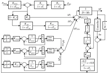
As an illustration, the block diagram of the considered hybrid micro grid along with renewable and storage energy devices and system physical nonlinearities is shown in Fig. 1.
3 The Proposed RL-PID Controller
3.1 Reinforcement Learning
Reinforcement learning is an algorithmic method based on trial and error, in which one or more agents learn an optimal control policy by interact with their environment (system under control) [26]. In other words, the environment is divided into several discrete states, in each state, there are a definite number of actions to be implemented. The intelligent agent learns to determine the optimal action that has to be applied to the system in each state [18]. In general, there are several methods for solving RL problems like adaptive heuristic critic (AHC), Q-learning, average reward (AR), and etc. [27]. In this paper, Q-learning is used to solve the proposed RL based frequency controller.
3.2 Q-Learning
The main advantages of Q-learning based controllers are a simple structure, independent of the model of the system under control, robustness against changes in the operating point and system uncertainties and adaptive behaviour [18, 28]. Q-learning based reinforcement learning assumes the environment (system under control) is divided into a finite number of states is shown with set S. Agent forms a matrix called Q, which has a value (initially ‘0’) for each set of action-state pairs and indicates the goodness of particular action in the corresponding state. In each time step, agent
Iranian Journal of Electrical and Electronic Engineering, Vol. 15, No. 1, March 2019 129 P F E SS PBESS PUC PESSs 1
DMs
F Co n tr o ll er u 1 WTG WTG K sT 1 s s K sT 1 T T K sT
PSol.
PWind + +
n K 1 FC FC K sT 1 AE AE K sT
(1Kn) PDEG
PFC
Pt +
+ ++ 1 R + FESS
K + 1
FESS T 1 s Time Delay Dead Zone BESS
K + 1
BESS T 1 s Time Delay Dead Zone UC
K + 1
UC T 1 s Time Delay Dead Zone DEG K + 1 DEG T 1 s Time Del ay 0.2 0.8 1 G s sT
Fig. 1 The block diagram of the considered hybrid micro grid.
calculates its state st, and based on a defined strategy selects action a among available actions of stat st. Immediately after applying the action, the agent takes a reward r from the environment and calculates its next state st+1. Then it updates the corresponding element of
the Q matrix. The goal of the agent in Q-learning method is to learn a strategy which maps the states to actions to maximize discounted long-term reward [29]. The discounted long-term reward of the system is given by Eq. (9).
1 0
kt t k
k
R r (9)
where r is the reward, γ is a number at the range 0 to 1 and is called discount factor. Q matrix is defined as:
1 0 ( , ) | ,
kt k t t
k
Q s a E r s s a a (10)
where π, s, a, and r are the control policy, current state, selected action, and the received reward, respectively. In each time step, Eq. (10) should be updated using optimal Bellman equation, which is given by Eq. (11).
1 max ( 1, 1) ( , )
t t t t t
a
Q r Q s a Q s a (11)
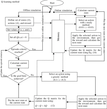
where αϵ (0, 1) and is called attenuation factor. The flowchart of the proposed Q-learning method is summarized in Fig. 2. It is evident from Fig. 2 that after completing the learning phase (offline simulation), the system will be switched to online simulation.
3.3 RL-PID
Fig. 3 shows the block diagram of the RL-PID controller. As can be seen, the RL-PID controller consists of two parts. The first part is a traditional PID controller that its coefficients are optimized using SSA [25] in this paper. It must be noticed that this section is fixed and is adjusted only once. The second part, which is a compatible controller, has two stages. In the preprocessing section, the system state after the previous action is determined by using the received signal discretization. In the other part, the RL control mechanism, in a supervisory manner, corrects the output of the PID controller utilizing information obtained in preprocessing stage. This part is variable and updated at any time step. As its name implies, reinforcement learning, this controller after applying an action to the system, receives the impact of it in a reward/penalty form and gives it a score in the corresponding state. Certainly, in each state of the system, an action with a higher score, is best suited to be implemented to the system.
4 A Short Overview of SSA
Salp is a tubular and floating sea creature that moves by pumping the water through its gelatinous body [25]. Similar to the other particle-based optimization methods, the position of the particles defined in an
n-dimensional space, where n is the number of optimization variables. The target which the Salp particles have to move towards it (the optimal problem) is a hypothetical source of food that is indicated by F. The particles leader updates its position using Eq. (12).
Iranian Journal of Electrical and Electronic Engineering, Vol. 15, No. 1, March 2019 130
Q-learning method
Offline simulation Online simulation
Define set of states {S}, actions {A}, and reward
Set values of α, γ, and ε
Set all Q(s,a) = 0
Episode criteria reached? Yes S w it c h t o o n li n e s im u la ti o n No Calculate current state
Is the goal been achieved? Yes U pda te t he e pi soi d c ri te ri a
No Select an action using
ε-greedy*
method (0.1< ε <0.3)
Apply the selected action to the environment, then get the reward and calculate the next state
Update the Q matrix for the current state using:
Q = Q + Q (12) Put the next state at
the current state
Calculate current state
Select an action with ε-reedy
method. (0.01< ε <0.03)
Apply the selected action to the environment, then get the reward and calculate the next state
Update the Q matrix for the current state using Eq. (16)
P u t t h e n e x t s ta te a t t h e c u rr e n t s ta te Start M e m o ry
*ε-greedy method is expressed in [24].
Fig. 2 Steps of the Q-learning solution method for RL.
u y + + Preprocessing i K s d K s p K + + +
RL
Salp swarm algorithm
URL
Fig. 3 Descriptive model of the proposed adaptive RL-PID controller.
1 2 3
1
1 2 3
(( ) ) 0
(( ) ) 0
j j j j
j
j j j j
F c ub lb c lb c
X
F c ub lb c lb c (12)
where 1
j
X refers to the position of the leader, Fj is the position of the food, ubj and lbj are upper and lower band of particle positions in jth dimension, respectively. Parameters c1 – c3 are random numbers. Generally
speaking, in optimization techniques, the optimization
process can be divided into two phases: exploration and exploitation. In the first phase, the algorithm combines random answers using random methods to find the best range of the existing answers. But in the second phase, the progressive changes in random responses are carried out with a lower percentage of randomness compared to the first phase [30].
The parameter c1 is very important because it balances
the exploration and exploitation phases, and calculated
Iranian Journal of Electrical and Electronic Engineering, Vol. 15, No. 1, March 2019 131
by Eq. (13).
2
4
( )
1 2
l L
c e (13)
where l is the current iteration and L is the maximum number of iterations. The parameters c2 and c3 are
random numbers generated using normal distribution in the range 0 to 1. Using Newton's displacement law, the position of the follower Salps is expressed by Eq. (14).
2 0 1 2
i j
X at v t (14)
wherei2,Xij is the position of particle i in dimension
j, t is time, v0 is the initial speed, avfinal v0 and
0
( )
v xx t. Since the concept of time is expressed in terms of iteration in the optimization process, and the interval of iterations is equal to 1. Also, taking into account the initial velocity of 0 for all particles, Eq. (14) can be simplified in the form Eq. (15).
1 1
( )
2
i i i
j j j
X X X (15)
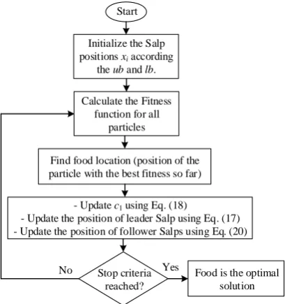
More details about the SSA can be found in Ref. [25]. Fig. 4 shows the simplified flowchart of SSA.
5 Optimization Results
In order to obtain the best dynamic performance of the PID and FOFPID controllers, their control coefficients optimized using the SSA. For the purpose of optimizing these controllers, an objective function defined based on the integral of time multiplied by absolute error (ITAE) criterion. In accordance with Eq. (16), in the simulation time interval and under micro-grid disturbances along
with the uncertain output of renewable resources, the area under the frequency deviation curve is considered as the controllers’ optimal criterion.
120
0
| |
J
t f dt (16)The optimization of the classical PID controller which has three control parameters, namely Kp, Ki, and Kd can be formulated as the constrained optimization problem of Eq. (17).
minimize subject to:
0 p, i, d 5
J
K K K
(17)
Likewise, the FOFPID controller has six control parameters which Ke, Kdf, Kpi, Kpd are the gain coefficients, and µ and λ are the fraction degrees of derivative and integrator components, respectively. Other details about the FOFPID controller, including the structure, the input and output membership functions, and the fuzzy rules are mentioned in [1]. In this paper, the excessive explanations have been ignored to avoid increasing the volume of the paper. Given this points, the problem of optimizing the FOFPID controller for controlling the frequency of the micro-grid is formulated by Eq. (18).
minimize subject to:
5 , , , 5
0.5 , 1
e df pi pd
J
K K K K
(18)
The optimization problems of Eqs. (17) and (18) are
Start
Yes
Initialize the Salp positions xiaccording
the ub and lb.
Calculate the Fitness
function for all
particles
Find food location (position of the particle with the best fitness so far)
- Update c1 using Eq. (18)
- Update the position of leader Salp using Eq. (17) - Update the position of follower Salps using Eq. (20)
Stop criteria reached?
Food is the optimal solution No
Fig. 4 The simplified flowchart of SSA.
Iranian Journal of Electrical and Electronic Engineering, Vol. 15, No. 1, March 2019 132
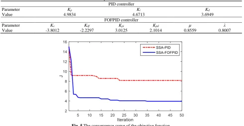
Table 1 SSA based control parameters of the PID and FOFPID controllers. PID controller
Parameter Kp Ki Kd
Value 4.9834 4.6713 3.6949
FOFPID controller
Parameter Ke Kdf Kpi Kpd µ λ
Value -3.8012 -2.2297 3.0125 2.1014 0.8559 0.8007
Fig. 5 The convergence curve of the objective function.
solved separately by SSA with 50 initial populations and 50 iterations. The optimization results and the convergence process of the objective function are shown in Table 1 and Fig. 5, respectively.
5.1 Ingredients of the RL Controller, State, Action and Reward/Penalty Function
Important to realize, the proposed RL controller is portable and can be added as a supervisory controller to any other kinds of controllers to improve their dynamic performance. In this paper, the PID controller is chosen, because along with its acceptable performance, has a simple structure and is widely used in the industry. Formerly, it was stated that the Q-learning method is used to solve the reinforcement learning in this paper. Another key point is that the Q-learning based controller's performance depends largely on how the states, actions, and reward/penalty functions are defined, which are described in more detail below.
5.1.1 States
Given that point, that the frequency oscillation enhancement is the primary objective of this paper, the ΔF signal is sampled and used as the feedback signal from the system under control to determine the system state. For this aim, the time interval from -0.02 to + 0.02 divided into 50 equal segments and Eq. (19) is utilized at each time step to determine the state of the system. The zero-centered state is called normal state, and the intelligent agent does not do anything in the normal state. In fact, this equation, in addition to determining the value of system frequency, it makes it clear whether the frequency oscillations are going to the instability or
moving towards the establishment [18].
(
,
)
t
d f
s
f
dt
(19)where st is the state of the micro-grid at time t and is a function of Δf and its derivative.
5.1.2 Actions
Although, there are no particular laws for defining of actions for RL based controllers, and this makes it a complex matter [20]. But it may be determined by inspiring from the output limits of the usual controllers that used for the same purpose [24]. Must be noticed, various actions can be defined for different states of the system and they can even be increased. These efforts have two positive and negative aspects. On the positive side, it can improve the dynamic performance of the controller by increasing the degree of freedom (the controller has more choices to perform). On the negative side, it increases the learning time extremely and makes it challenging (or even impossible) to find the optimal control policy. With this in mind, in this paper, the same actions are suggested for all states and expressed by Eq. (20).
0.02, 0, 0.02
all states
A (20)
where A is the action set for all states of the system.
5.1.3 Reward/Penalty Function
The reward/penalty function is important because it assesses the degree of satisfaction from the action taken
Iranian Journal of Electrical and Electronic Engineering, Vol. 15, No. 1, March 2019 133
in the previous state in line with the overall goal. In the event that the system state is st, the agent utilizes its experience to perform the best action (a) among the actions defined for state st. Without delay, the agent receives a reward/penalty from the system under control concerning the performed action. On the basis of this reward/penalty, the agent assigns a score for a pair of (st, a) and updates the corresponding element of Q matrix. If the score is positive, the probability of performing the action a at the state st increases for the next times. Otherwise, if the score is negative (penalty), the agent selects the action a with a lower probability in the state st, in next times. With this intention that the primary objective of this paper is frequency control, therefore Δf signal is selected for determination of reward/penalty for corresponding (st, a) pairs. In essence, if an action causes the system to go out of the normal state, it will be fined. In return, if an action causes the system to go to the normal state, will receive the highest reward. In summary, the reward/penalty function is described by Eq. (21), in this paper.
1
1
1
1 If is normal state
1 If is normal state and is not normal state 1 Otherwise
(1 ( ))
t
t t
t
t k t
s
s
s
f k
(21)
where t is the time step.
6 Results and Discussion
Finally, in order to assess the RL controller's ability for mitigation of the frequency deviations, first, the dynamic equations of the micro-grid of Fig. 1 are simulated in MATLAB R2015b environment. Then the superiority of the proposed controller is proved in
realistic scenarios compared to traditional and FOF PID controllers. It should be noted that the simulation time step and sampling time are considered equal to 1 and 50 milliseconds, respectively. Moreover, in computer simulations, physical constraints on energy storage (ES) devices and DEG, including dead band and generation rate constraints (GRC), are considered. For this reason, the dead band is considered equal to 20ms and located at the input of the devices and GRC is considered as 0.02, 0.005, 1.2, and 0.001 for FESS, BESS, UC, and DEG, respectively. In addition, variable wind speed and solar radiation have been created using Eqs. (22) and (23), respectively. More details are given in [11].
4
1 1
0.8 10 1 10
10
10 1
wind
P
s
(22)
where U( 1,1) , and is a function of Heaviside step function.
. 4
1 1
0.7 2 1 10
20
10 1
sol
P
s
(23)
where U( 1,1) .
6.1 Scenario1: Performance of the Controllers in Nominal Conditions of the Hybrid Micro-grid
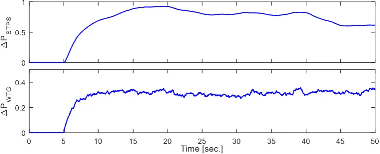
In this scenario, it is assumed that all the elements exist in the hybrid micro-grid are in their nominal conditions. The renewable resources do not have production from the beginning, and they start production at time 5s according to the pattern shown in Fig. 6. Moreover, the sudden load changes of 10 and 20 percent occur at seconds 5 and 65, respectively.
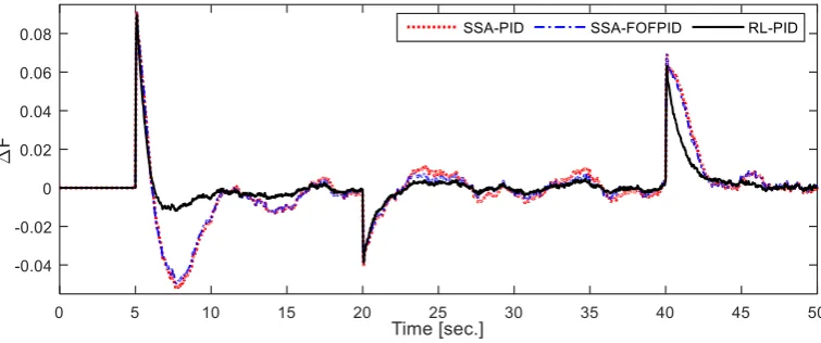
Under those circumstances, the dynamic frequency response of the proposed control strategy is shown in Fig. 7 compared to traditional and FOF PID controllers.
Fig. 6 The renewable resources production in scenario 1.
Iranian Journal of Electrical and Electronic Engineering, Vol. 15, No. 1, March 2019 134
Fig. 7 The dynamic response of the proposed control strategies in Scenario 1.
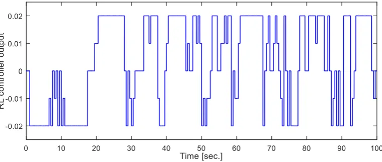
Fig. 8 The output signal of the RL controller during simulation time in Scenario 1.
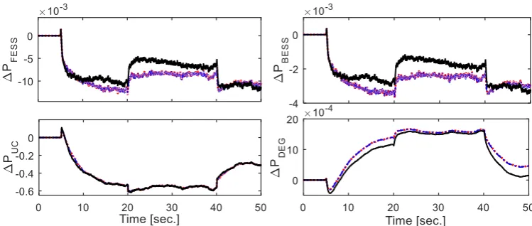
Fig. 9 The power absorbed/supplied by ES devices and DEG in Scenario 1; Solid: RL, Dashed: FOF PID, and Dotted: PID.
As shown in Fig. 7, it is obvious that in the first overshoot/undershoot after disturbance, the performance of the RL has a mild superiority over the other control methods. This is due to the delay in detecting the turmoil by the intelligent agent. From Fig. 7, after few sampling steps, Δf is going out of the normal range and the controller recognizes the disturbance, then the intelligent agent immediately begins to apply a supplementary control signal to improve the dynamics of the system. Fig. 8 shows the output signal of the RL
controller during simulation time.
Considering Figs. 7 and 8, it is evident that the controller is inactive and when the frequency oscillations start, it will be activated. In the time interval of 0 to 5 seconds, which disturbance has not yet occurred, the RL controller is inactive (its output is zero). Once turbulence is triggered, it will be activated and performs the optimal control policy. The output power of various ES devices along with DEG is shown in Fig. 9.
Iranian Journal of Electrical and Electronic Engineering, Vol. 15, No. 1, March 2019 135 6.2 Scenario 2: Performance of the Controllers in
Presence of Changing in Hybrid Micro-grid Components
As can be seen from Fig. 9, the output power of UC is much more than the other ES devices. Thus, UC parameter changing can be considered as the worst test case for robustness of the controllers against system parameter changes. Therefore, in this scenario, 2 percent increase in the gain along with 2 percent decrease in the time constant of UC energy storage device are assumed. All the other conditions are as same as the conditions of
scenario 1. Fig. 10 shows the frequency deviation of the hybrid micro-grid with three control methods.
Fig. 10 shows that the changes in the UC parameters have caused the frequency oscillations to be continued more in comparison with scenario 1 after disturbance. Under those circumstances, it is evident from Fig. 10 that the dynamic performance of the proposed control mechanism is superb compared to the PID control method. Further, the optimal control signal of the RL and the power absorbed/supplied by ES devices and DEG are shown in Figs. 11 and 12, respectively.
Fig. 10 The dynamic response of the proposed control strategies in Scenario 2.
Fig. 11 The output signal of the RL controller during simulation time in Scenario 2.
Fig. 12 The power absorbed/supplied by ES devices and DEG in Scenario 2; Solid: RL, Dashed: FOF PID, and Dotted: PID.
Iranian Journal of Electrical and Electronic Engineering, Vol. 15, No. 1, March 2019 136 6.3 Scenario 3: Performance of the Controllers with
Large Variations in the Output Power of the Renewable Resources Along with the Pattern Load Changes
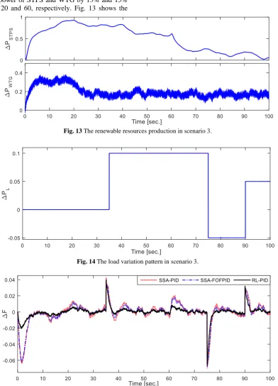
In this scenario, in order to demonstrate the excellent performance of the proposed controller compared to the classical PID and intelligent FOFPID controllers, a challenging condition is produced by sudden decreasing the output power of STPS and WTG by 13% and 15% in seconds 20 and 60, respectively. Fig. 13 shows the
power generated by renewable resources in scenario 3. Additionally, to make a more realistic scenario a pattern load change accordance with Fig. 14 is considered. The performance of three control strategies is shown in Fig. 15.
The optimal control signal generated by the RL controller and the powers absorbed/supplied by ES devices and DEG are shown in Figs. 16 and 17, respectively.
Fig. 13 The renewable resources production in scenario 3.
Fig. 14 The load variation pattern in scenario 3.
Fig. 15 The dynamic response of the proposed control strategies in Scenario 3.
Iranian Journal of Electrical and Electronic Engineering, Vol. 15, No. 1, March 2019 137
Fig. 16 The output signal of the RL controller during simulation time in Scenario 3.
Fig. 17 The powers absorbed/supplied by ES devices and DEG in Scenario 3; Solid: RL, Dashed: FOF PID, and Dotted: PID.
7 Discussion
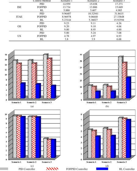
As can be seen in some cases of simulations, the proposed RL control method has a mild superiority over the other PID and FOFPID controllers. For this reason, in order to demonstrate the superiority of the RL control structure compared to the other control methods, four appropriate numerical criteria are chosen and computed for all scenarios. Integral of squared error (ISE), ITAE, overshoot (OS) and undershoot (US) are the criteria which are computed according to Eqs. (24)-(27), respectively. Table 2 and Fig. 18 show the numerical time domain analysis of the dynamic performance of the proposed RL controller compared to PID and FOFPID in damping of hybrid micro-grid frequency deviations.
2
0
1000 ( )
sim
t
ISE
f dt (24)0
. | |
sim
t
ITAE
t f dt (25)max( ) 100
OS f (26)
| min( ) | 100
US f (27)
where tsim is equal to 120 in all scenarios.
As can be seen in Table 2 and Fig. 18, the dynamic performance of the RL controller has a remarkable superiority over the PID and FOFPID control methods. In the final analysis, in order to emphasize the superiority of the proposed controller compared to PID and FOFPID controllers, the results shown in Table 2 are statistically analyzed. In this regard, it can be seen that the RL controller has improved the index ISE 60%, 62%, and 71% compared to PID and 57%, 60%, and 68% compared to FOFPID in scenarios 1, 2, and 3, respectively. In the view of ITAE index, frequency deviations have been improved approximately 50% compared to PID and 41% compared to FOFPID in all three scenarios. It must be noted that the US and OS were calculated in the worst case of each controller. As shown in Fig. 19, the OS index have been decreased approximately 2%-6% compared to PID and 2% compared to FOFPID controller. The reason for low impact of the RL control structure on the OS is previously described in scenario 1. Similarly, the RL controller has enhanced the US of the frequency deviations by 24%, 25%, and 5% compared to PID and 20%, 21%, and 3% compared to FOFPID in scenarios 1, 2, and 3, respectively. In conclusion, as shown above, the proposed consistent mechanism based on RL can
Iranian Journal of Electrical and Electronic Engineering, Vol. 15, No. 1, March 2019 138
optimally control the frequency deviations of a hybrid micro-grid with high penetrations of renewable and storage energy devices. Another Key point is that this simple and portable controller can be applied to the
classical existent controllers to make them robust and adaptive with an excellent dynamic performance even better than the intelligent fuzzy logic based controllers.
Table 2 Time domain performance indices for RL controller compared to PID and FOFPID.
Control Method Scenario 1 Scenario 2 Scenario 3
ISE
PID 14.959 15.038 17.271
FOFPID 13.734 13.806 15.669
RL 5.888 5.607 4.985
ITAE
PID 9.96407 10.32941 31.8615
FOFPID 8.96978 9.06640 27.33848
RL 5.23144 5.36027 15.92594
OS
PID 9.23 9.11 4.26
FOFPID 9.20 9.10 4.06
RL 9.00 8.95 4.00
US
PID 5.00 5.24 7.08
FOFPID 4.78 4.97 6.93
RL 3.8 3.9 6.68
(a) (b)
(c) (d)
PID Controller FOFPID Controller RL Controller
Fig. 18 Time domain performance indices for RL controller compared to PID and FOFPID: a) ISE, b) ITAE, c) OS and d) US.
Iranian Journal of Electrical and Electronic Engineering, Vol. 15, No. 1, March 2019 139 8 Conclusions
The precise coordination of the mechanisms for controlling renewable resources and energy storages for suppressing the oscillation of frequency in the hybrid micro-grids is always considered as a challenge due to uncertainties in the wind and solar power. This challenge needs the advanced and intelligent control methods for damping the grid frequency deviations. For this reason, this paper, is suggested an RL based control mechanism for controlling the frequency of hybrid micro-grids. The suggested control strategy integrates the RL features with the traditional PID controller and provides a simple, model-free, adaptive, and robust control method against system parameter changes and operating conditions. In this paper, the RL controller is
added to a traditional PID controller as a
complementary controller. Because the PID controller has a satisfactory performance in addition to its simple structure and extensive use in the industry. Eventually, in order to evaluate the effectiveness of the proposed controller, a hybrid micro-grid with high penetration of renewable and energy storage devices and physical limits such GRC, GDB and time delay was modelled. Then several realistic scenarios and challenging conditions were considered to demonstrate the excellent dynamic performance of the proposed RL based controller compared to classical and FOF PID controllers that were optimized using SSA. Simulation results expressively demonstrate the superiority of the proposed control mechanism compared to PID and FOFPID control methods under different operating conditions and uncertainties of the system parameters. In the final analysis, suitable numerical time domain criteria such ISE, ITAE, OS, and US were calculated for the two control methods. Clearly, the results confirm the superiority of the proposed control method. As can be seen, the proposed controller has improved the ITAE and ISE more than 50% in different operating conditions. In addition, OS is enhanced 2%-6% in all scenarios. Also, US, the other considered performance index has been decreased more than 20% in all conditions. Thanks to its simple and portable structure, the RL controller can be applied as a supervisory controller to any other control system to improve its performance. For future works, our focus will be on the other solution methods of reinforcement learning and application of multi-agent learning in controlling micro-grids.
References
[1] I. Pan and S. Das, “Fractional order fuzzy control of hybrid power system with renewable generation using chaotic PSO,” ISA Transactions, Vol. 62, pp. 19–29, 2016.
[2] H. Shayeghi and A. Younesi, “A robust discrete fuzzyP+fuzzyI+fuzzyD load frequency controller for
multi-source power system in restructuring
environment,” Journal of Operation and Automation in Power Engineering, Vol. 5, No. 1, pp. 61–74, 2017.
[3] J. Yan, Y. Zhai, P. Wijayatunga, A. M. Mohamed, and P. E. Campana, “Renewable energy integration with mini/micro-grids,” Applied Energy, Vol. 201, pp. 241–244, 2017.
[4] M. F. M. Arani and Y. Mohamed, “Cooperative control of wind power generator and electric
vehicles for microgrid primary frequency
regulation,” IEEE Transactions on Smart Grid, Vol. 9, No. 6, pp. 5677–5686, 2017.
[5] F. Teng, Y. Mu, H. Jia, J. Wu, P. Zeng, and G. Strbac, “Challenges on primary frequency control and potential solution from EVs in the future GB electricity system,” Applied Energy, Vol. 194, pp. 353–362, 2017.
[6] A. A. K. Arani, H. Karami, G. B. Gharehpetian, and M. S. A. Hejazi, “Review of flywheel energy storage systems structures and applications in power
systems and microgrids,” Renewable and
Sustainable Energy Reviews, Vol. 69, pp. 9–18, 2017.
[7] B. Papari, C. S. Edrington, I. Bhattacharya, and G. Radman, “Effective energy management of hybrid AC-DC microgrids with storage devices,”
IEEE Transactions on Smart Grid, Early Access, 2017.
[8] M. Antonelli, S. Barsali, U. Desideri, R. Giglioli, F. Paganucci, and G. Pasini, “Liquid air energy storage: Potential and challenges of hybrid power plants,” Applied Energy, Vol. 194, pp. 522–529, 2017.
[9] S. K. Pandey, S. R. Mohanty, N. Kishor, and J. P. S. Catalão, “Frequency regulation in hybrid power systems using particle swarm optimization and linear matrix inequalities based robust controller design,” International Journal of Electrical Power & Energy Systems, Vol. 63, pp. 887–900, 2014.
[10]D. C. Das, A. K. Roy, and N. Sinha, “PSO based frequency controller for wind-solar-diesel hybrid energy generation/energy storage system,” in
International Conference on Energy, Automation and Signal, pp. 1–6, 2011.
[11]D. C. Das, A. K. Roy, and N. Sinha, “GA based frequency controller for solar thermal–diesel–wind hybrid energy generation/energy storage system,”
International Journal of Electrical Power & Energy Systems, Vol. 43, pp. 262–279, 2012.
Iranian Journal of Electrical and Electronic Engineering, Vol. 15, No. 1, March 2019 140
[12]S. Sinha and S. S. Chandel, “Review of recent trends in optimization techniques for solar photovoltaic–wind based hybrid energy systems,”
Renewable and Sustainable Energy Reviews, Vol. 50, pp. 755–769, 2015.
[13]S. M. Malik, X. Ai, Y. Sun, C. Zhengqi, and
Z. Shupeng, “Voltage and frequency control
strategies of hybrid AC/DC microgrid: a review,”
IET Generation, Transmission & Distribution, Vol. 11, pp. 303–313, 2017.
[14]M. H. Khooban, T. Niknam, F. Blaabjerg, and T. Dragičević, “A new load frequency control strategy for micro-grids with considering electrical vehicles,” Electric Power Systems Research, Vol. 143, pp. 585–598, 2017.
[15]M. H. Khooban, T. Niknam, F. Blaabjerg, P. Davari, and T. Dragicevic, “A robust adaptive load frequency control for micro-grids,” ISA Transactions, Vol. 65, pp. 220–229, 2016.
[16]M. R. Khalghani, M. H. Khooban, E. Mahboubi-Moghaddam, N. Vafamand, and M. Goodarzi, “A self-tuning load frequency control strategy for microgrids: Human brain emotional learning,”
International Journal of Electrical Power & Energy Systems, Vol. 75, pp. 311–319, 2016.
[17]L. Chen-Ching, J. Juhwan, G. T. Heydt, V. Vittal, and A. G. Phadke, “The strategic power infrastructure defense (SPID) system. A conceptual design,” IEEE Control Systems, Vol. 20, pp. 40–52, 2000.
[18]A. Younesi, H. Shayeghi, and M. Moradzadeh, “Application of reinforcement learning for generating optimal control signal to the IPFC for
damping of low-frequency oscillations,”
International Transactions on Electrical Energy Systems, Vol. 28, No. 2, p. e2488, 2017.
[19]D. Ernst, M. Glavic, and L. Wehenkel, “Power systems stability control: reinforcement learning framework,” IEEE Transactions on Power Systems, Vol. 19, pp. 427–435, 2004.
[20]R. Hadidi and B. Jeyasurya, “Reinforcement learning based real-time wide-area stabilizing control agents to enhance power system stability,”
IEEE Transactions on Smart Grid, Vol. 4, pp. 489– 497, 2013.
[21]J. G. Vlachogiannis and N. D. Hatziargyriou, “Reinforcement learning for reactive power control,” IEEE Transactions on Power Systems, Vol. 19, pp. 1317–1325, 2004.
[22]V. Nanduri and T. K. Das, “A reinforcement learning model to assess market power under auction-based energy pricing,” IEEE Transactions on Power Systems, Vol. 22, No. 1, pp. 85–95, 2007.
[23]M. Esmaeili, H. Shayeghi, H. Mohammad Nejad, and A. Younesi, “Reinforcement learning based PID controller design for LFC in a microgrid,”
COMPEL-The International Journal for Computation and Mathematics in Electrical and Electronic Engineering, Vol. 36, No. 4, pp. 1287– 1297, 2017.
[24]H. Shayeghi and A. Younesi, “An online Q-learning based multi-agent LFC for a multi-area multi-source power system including distributed energy resources,” Iranian Journal of Electrical and Electronic Engineering, Vol. 13, No. 4, pp. 385– 398, 2017.
[25]S. Mirjalili, A. H. Gandomi, S. Z. Mirjalili, S. Saremi, H. Faris, and S. M. Mirjalili, “Salp swarm algorithm: A bio-inspired optimizer for engineering
design problems,” Advances in Engineering
Software, Vol. 114, pp. 163–191, 2017.
[26]C. Weber, M. Elshaw, and N. M. Mayer,
Reinforcement learning, theory and applications. I-TECH Education and Publishing, 2008.
[27]L. P. Kaelbling, M. L. Littman, and A. W. Moore, “Reinforcement learning: A survey,” Journal of Artificial Intelligence Research, Vol. 4, pp. 237– 285, 1996.
[28]R. S. Sutton and A. G. Barto, Reinforcement learning: An introduction. MIT Press, 2005.
[29]C. J. C. H. Watkins and P. Dayan, “Technical note: Q-Learning,” Machine Learning, Vol. 8, No. 3-4, pp. 279–292, May 1992.
[30]S. Mirjalili, “SCA: A Sine Cosine Algorithm for solving optimization problems,” Knowledge-Based Systems, Vol. 96, pp. 120–133, Mar. 2016.
A. Younesi received B.Sc. and M.Sc. degrees both in Electrical Engineering from Faculty of Technical Engineering Department of the Mohaghegh Ardabili University, Ardabil, Iran in 2012 and 2015 respectively. Currently He is a Ph.D. student in Technical Engineering Department of the University of Mohaghegh Ardabili, Ardabil, Iran. His areas of interest are application of artificial intelligence in power system automation and control, application of reinforcement learning to power system control, fuzzy systems, and heuristic optimization in power system control. He is a student member of Iranian Association of Electrical and Electronic Engineers (IAEEE) and IEEE.
Iranian Journal of Electrical and Electronic Engineering, Vol. 15, No. 1, March 2019 141
H. Shayeghi received the B.Sc. and M.Sc. degrees in Electrical and Control Engineering in 1996 and 1998, respectively. He received his Ph.D. degree in Electrical Engineering from Iran University of Science and Technology (IUST), Tehran, Iran in 2006. Currently, he is a full Professor in Technical Engineering Department of University of Mohaghegh Ardabili, Ardabil, Iran. His research interests are in the application of robust control, artificial intelligence and heuristic optimization methods to power system control design, operation and planning and power system restructuring. He has authored and co-authored of 5 books in Electrical Engineering area all in Farsi, one book and two book chapters in international publishers and more than 330
papers in international journals and conference proceedings. Also, he collaborates with several international journals as reviewer boards and works as editorial committee of three international journals. He has served on several other committees and panels in governmental, industrial, and technical conferences. He was selected as distinguished researcher of the University of Mohaghegh Ardabili several times. In 2007 and 2010 he was also elected as distinguished researcher in engineering field in Ardabil province of Iran. Furthermore, he has been included in the Thomson Reuters’ list of the top one percent of most-cited technical Engineering scientists in 2015 and 2016, respectively. Also, he is a member of Iranian Association of Electrical and Electronic Engineers (IAEEE) and Senior member of IEEE.
© 2019 by the authors. Licensee IUST, Tehran, Iran. This article is an open access article distributed under the terms and conditions of the Creative Commons Attribution-NonCommercial 4.0 International (CC BY-NC 4.0) license (https://creativecommons.org/licenses/by-nc/4.0/).