AUT J. Elec. Eng., 49(1)(2017)53-62 DOI: 10.22060/eej.2016.814
Steganography Scheme Based on Reed-Muller Code with Improving Payload and Ability
to Retrieval of Destroyed Data for Digital Images
A. M. Molaei*, M. H. Sedaaghi, H. Ebrahimnezhad
Department of Electrical Engineering, Sahand University of Technology, Tabriz, Iran
ABSTRACT: In this paper, a new steganography scheme with high embedding payload and good visual quality is presented. Before embedding process, secret information is encoded as a block using Reed-Muller error correction code. After data encoding and embedding into the low-order bits of the host image, modulus function is used to increase the visual quality of stego image. Since the proposed method is able to embed secret information into more significant bits of the image, it has improved embedding payload. The steps of extracting data from the host image are independent of the original image. Therefore, the proposed algorithm has a blind detection process which is more suitable for practical and online applications. The simulation results show that the proposed algorithm is also able to retrieve destroyed data by intentional or unintentional attacks such as the addition of noise and filtering due to the use of the error correction code. In addition, the payload is improved in comparison with the same techniques.
Review History:
Received: 20 February 2016 Revised: 26 October 2016 Accepted: 29 October 2016 Available Online: 2 November 2016
Keywords:
Blind Detection High Payload
Low-Order Bits Embedding
Retrieval of Destroyed Data
Steganography
1- Introduction
Data hiding is the knowledge of embedding original message into a host media and then extracting it from received data [1-4]. What should be considered in this process is that cover media should not be high visually distorted after embedding; i.e. eye is not able to distinguish a change in cover media. Cryptography, digital watermarking and steganography are three branches of data hiding techniques [5-7]. In cryptography, sender converts plain text to cipher text using a secret key and it is decrypted on the side of the receiver to extract plain text. In steganography, the embedded data do not have relation to cover media; in other words, the presence of a message in cover media cannot be detected while in watermarking, the embedded data are related to cover media and cannot be removed or replaced. In this paper, we use grayscale images as cover media for steganography that these images are called host images. The obtained image after embedding into the host image is called stego image.
In terms of detection technique, data hiding systems are categorized into two types of blind and non-blind [8-10]. In blind systems, the original data (cover) is not needed in detection stage, i.e. the message can be extracted directly from received data without the original host media. In this technique, the authorized user is able to extract message by a secret key. In non-blind systems, the original data is needed in detection stage. In practical applications, blind systems are more suitable than non-blind systems; but since the message is transmitted to the receiver in the presence of noise, non-blind data hiding systems have fewer problems for detection. For solving this problem in blind data hiding systems, additional information is added to the original message that is called
information encoding. Our proposed detection method in this paper is blind.
In terms of embedding method, there are several common techniques for steganography: Least Significant Bit (LSB) substitution, LSB matching and Pixel-Value Differencing (PVD) [11]. In the first type technique which is the most common and simplest method for steganography, secret bits directly replace the LSBs of the host image. In the second type technique, the LSBs of host image are modified and in the third type technique, the difference between two consecutive pixels is calculated to determine the number of embedded bits.
any image while these variations are less observed with eyes in edge areas. YANG et al. [18] proposed an adaptive substitution method to embed data into the low-order bits with the aim of preventing sudden changes on the edges of the image and also achieving a better quality of stego image. Their method uses masking of light, edges and texture of host image to estimate the number of LSBs. In their work, more bits are embedded in the pixels belonging to the regions of insensitive to noise in comparison with regions of sensitive to noise. In addition, an optimal pixel adjustment process is used to enhance the visual quality of the stego image using LSB substitution. Zhang et al. [19] investigated a method for improving the capacity and the efficiency of embedding in grayscale images. To this end, they presented two algorithms, called high capacity of information hiding (HCIH) and high-quality information hiding (HQIH). The first algorithm aims to achieve high embedding rate and the second algorithm aims to achieve high embedding efficiency. In the study [20], in addition to the LSB substitution technique, a mixed edge detection mechanism is also employed to increase payload. In this mechanism, the combination of Canny edge detection and Log edge detection techniques is used. A second-order steganographic (SOS) method based on pixel pair matching and modification direction exploiting (MDE) is provided in [21]. Unlike the MDE-based methods [22-26] in which only one secret digit in base B can be concealed into each cover pixel pair, the SOS method is able to perform it for two secret digits.
Crandall [27] for the first time introduced the matrix encoding idea and in 2001 Westfeld [28] implemented this idea in his work called F5-a steganography algorithm. Matrix encoding uses linear codes to increase the visual quality of stego image by preserving high embedding capacity. Zhang et al. [29] proposed methods called Hamming+1 and Golary+2 using error correction binary codes which improved visual quality and embedding capacity. Chang [30] could increase embedding payload in methods [27] and [29] using error correction code of (7, 4) Hamming and LSB embedding. Singh and Siddiqui [31] proposed a robust steganography algorithm based on discrete cosine transform (DCT), Arnold transform and chaotic system. Their algorithm is robust against JPEG compression, the addition of noise, low pass filtering, and cropping attacks.
What was presented in most of the provided methods is a trade-off between payload and visual quality of the stego image. On the other hand, the destruction of stego image with attacks such as the addition of noise or filtering which is done to remove or manipulate important and secret information is one of the important aspects of steganography algorithm design. In the field of data hiding, several papers have been presented to improve payload and increase the visual quality of images. Several algorithms have been also presented to reduce destruction of images after attacks. However, there are limited number of papers which have paid attention to all of the above aspects. Considering the existing sensitivities in military fields, legal fields etc., it is important to provide new methods which concurrently consider all of the three problems mentioned above (payload, visual quality, and robustness against attacks). This study aims to improve the payload and the robustness against destruction parameters (with maintaining the good visual quality).
In this paper, we consider robustness against destructive attacks, such as the addition of noise and filtering using
Reed-Muller codes while introducing a new blind steganography algorithm which provides high embedding capacity with a good visual quality. To enhance the quality of stego image, we will use modulus function in the embedding process. To demonstrate the superiority of our proposed method, we will perform different tests on test images and compared results with similar methods. Results of the tests show the extraordinary performance of our proposed method.
Rest of this paper is organized as follows: in section 2, we review the related literature and works. In section 3, we introduce Reed-Muller codes and their encoding and decoding structures. In section 4, we completely describe the proposed algorithm. Section 5 presents simulations and discusses results. In section 6, conclusions are presented.
2- Related Works
In this section, firstly, the proposed method of Chang [30] will be described. Then, we will introduce the low-order bits substitution method proposed by Thein and Lin [13] to improve the visual quality of stego image.
A.(7, 4) Hamming Method
Chang’s method [30] employs (7, 4) Hamming code to hide information. First, it forms 16 classes each, including eight different bit strings of length seven. Then, seven bits of the secret data were read and divided into two parts of three bits and four bits. The 4-bit part is used for selecting one of 16 classes and the 3-bit part is used for selecting one of eight bit strings. Then to embed information, the LSB content of the 7 pixels from host image replaces with the selected bit string. The above process is repeated for the remaining secret data on the next pixels of host image to embed all secret data. The maximum length of data which can be embedded with method [30] into an image with a size of H×W is equal to H×W−1. In extraction stage, a seven-bit sequence from the image pixels is read and the LSB content of each pixel is separated and is juxtaposed as a 7-bit string. This 7-bit string is multiplied by parity check matrix relating to (7, 4) Hamming code to obtain 3-bit syndrome vector. By combining this 3-bit vector and other 4 bits, the embedded 7 bits are extracted. This operation is repeated until all of the embedded bits are extracted. One of the weaknesses of Chang’s method [30] is its limited embedding payload (maximum H×W−1 bits) because data can be only embedded into the LSB of each pixel. On the other hand, (7, 4) Hamming code is only able to correct an error bit and this can reduce the efficiency of extraction module when encountering hard attacks. Our proposed method does not have any of the two limitations above. In fact, the proposed method while improves the robustness against destruction and maintains the visual quality (using modulus function), will not be faced with the restriction of the payload.
B. Embedding Low-Order Bits Using Modulus Function The method [13] embeds the secret data into the low-order bits of host image pixels using modulus function. Assuming data are embedded in n low-order bits of each pixel, the data are decomposed into n -bit units. The decimal value of each of these units (xi) will be in the range of 0 to 2n −1. To embed
the i -th unit (xi) in i -th pixel of host image (yi), first, the
difference value is calculated from Eq. (1):
where Z=XmodY is the remainder of the division of X by Y. Then, the minimal difference of di is calculated from Eq. (2):
( mod 2 )
= − n
i i i
where ⌊x⌋ is the largest integer which does not exceed x and ⌈x⌉ is an integer which is obtained from upward rounding of value x. Since value d`i may be out of the range from 0 to 255
in some cases, the modified value of the i -th pixel of host image after embedding ( ) is calculated from Eq. (3):
To extract the embedded data, it is enough to use the following equation:
where n is the number of the low-order bits used for embedding, is the value of the i -th pixel from stego image and xi is the value which is hidden into n low-order bits of the pixel . In this paper after encoding, in order to improve the visual quality of stego image, we embed data using low-order bits substitution method which is proposed by Thein and Lin [13].
3- Reed-Muller Codes
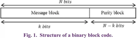
In communication sciences, error correction code is an algorithm by which it is possible to detect and correct errors in the received data [32, 33]. A set of error correction codes is divided into two subsets of block codes and convolutional codes. Assuming that k is the length of the message and N is the length of the codeword and N≥K , block codes divide the data into k -bit blocks to form u=(u0,ui,...,uk-1) and after encoding, a codeword c=(c0,c1,...,cN-1) is generated. Block codes have N−k parity bit and are decoded as a block to block. Fig. 1 shows the structure of a binary block code.
Reed-Muller code is usually shown as RM(r,m) where r and m are positive integers and 0≤r≤m . In RM(r,m) , the length of message and codeword are calculated using equations (5) and (6), respectively:
The maximum number of error bits which this code is able to correct is equal to:
In this paper, we will use Reed-Muller (R-M) codes for encoding secret data to be embedded in low-order bits of host image and then decoding low-order bits of stego image to extract hidden information. In the following, we describe R-M encoding and decoding method.
A. Reed-Muller Encoding
For a Reed-Muller code from r order and length of codeword N=2m , generator matrix is defined as [33]:
where , for
1≤i≤m which vi has a length of equal to 2m.
Assuming that we want to encode binary message u, binary codeword c is generated by binary multiplication operation , that is:
where the length of u and c is k and N , respectively. B. Reed-Muller Decoding
One of the techniques for decoding Reed-Muller codes is known as multiple error correction decoding algorithm which was presented by Reed [33]. Reed’s decoding process uses majority logic to determine the sent bit. Assuming a RM(r,m) code with input message
, the corresponding codeword will be as:
Assuming received vector x=(x0,x1,...,xN-1) , decoding process
includes r+1 stage. For where , an index set is formed as:
(5) (6) (2) (7) (8) (9) (10) (11) (3) (4) '
2 1 2 1
2 2
2 1
2 2 1
2 2 1 2 2 2 − − − ≤ ≤ −
= + − + ≤ < −
−
− < <
n n i i n n n
i i i
n
n n
i i
d if d
d d if d
d if d
ˆi y ˆi y ˆi y ' ' ' ' ' '
0
255
ˆ
2
0
2
255
+
≤
+
≤
=
+
+
+
<
+
−
+
>
i i i i
n
i i i i i
n
i i i i
y
d
if
y
d
y
y
d
if y
d
y
d
if y
d
ˆ mod2
=
ni i
x
y
Fig. 1. Structure of a binary block code.
0 = =
∑
r i m k i 2 = m N2
1
2
−
−
=
m rt
0 1 2 1 2 1 3 1 1 2 31 2 − − + − + × = ( , ) v v v v v v v v v v v v v
v v v
m
RM r m
m m
m r m r m k N
G
0 211 1
=
v
m 2 1 2 1 2 1 2 1
00 011 100 011 1
− −
− −
=
v
i i
i i
i
= ∗ ( , )
c u GRM m r
(
0 1 1 2 −1 1 2 − +1 − +2)
= , , , , , , ,...,
u u u, , ,u um, , ,um m,u r, ,um r m r m
(
)
1 1 1 1 1 1
1 1 2
1 2 1 1 1 2
0 1 1
0 0
1 1
1
−
≤ ≤ ≤ < ≤
≤ < < < ≤ =
= + +
+ +
∑
∑
∑
c , , ,
v v v v
v v v
r r
r
N
i i i i i i
i m i i m
i i i i i i
i i i m
c c c
u u u u
u
1 2
1≤ <i i <<ir l− ≤m
0
≤ ≤
l r
{
{ }
}
1 2
1 2
1 1 1
1 1 1
1
2 2 2
0 1 1
− − − − − − − − − + + + ∈ ≤ ≤ − : ,
r l
r l
j
i i i
i i i
i
S a a a
which is a set of 2r-l nonnegative integer members and values of less than 2m. Consider E as a set of integer members of {0,1,...,m−1} which are not member of {i1−1,i2−1,...,ir−l−1}, i.e.:
where . Now, form a set of integers as:
which has 2m−r+l nonnegative integer members. Now, form a set of indices as follows for each q∈Sc :
Then, decision equations in l -th decoding stage are obtained from Eq. (15):
The above relation follows binary addition rule and includes 2m−r+l equations in each stage. If most of the results obtained from these decision equations are zero, input message ui1i2...ir-l will be decoded as u*
i1i2...ir-l=0 , and if they are one, ui1i2...ir-l will be decoded as u*
i1i2...ir-l=1.
Assuming completion of the l -th stage of decoding process, form the modified received vector as:
In the above relation, x(l−1) is the modified received vector in l -th stage of decoding and x(0)=x . Now, we go to the next stage
and repeat the above process until the end of the r+1 stage to decode all received bits.
4- Proposed Method
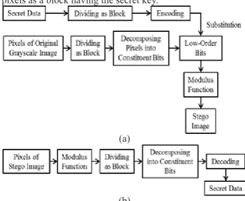
In this section, we present a steganography scheme with high embedding payload which is robust against the attacks. The proposed method can compete with the similar methods in both cases. Since there is no need for accessibility of the original image to extract secret data, the proposed method is considered as a blind steganography technique. Overall, a block diagram of the proposed method is shown in Fig. 2. In the proposed method, we first divide the sequence of pixels of the host image as a block. Then, secret bit strings are encoded by Reed-Muller block codes. This encoding will give rise to the correction and retrieval of the data which have been destroyed. Secret data can include binary information obtained from an image, a text or any kind of data in binary format. For example, if the desired data for hiding are textual, it can be converted into binary data using ASCII codes. Since the effect of change in values of the first to eight bits is different in a grayscale image with 8-bit pixels (for example, change in value of the first bit creates smaller visual distortion compared with the change in value of the second bit), we will use different R-M codes with different parameters of r and m to encode information for hiding it into
pixel bits of digital image. After bits are encoded, we embed them by method [13] into the low-order bits of the host image. Since in this paper, we use more significant bits in addition to LSB for embedding data, the goal of applying embedding method of Thein and Lin [13] is to reduce Mean Square Error (MSE) between two images before and after embedding and as a result, we achieve higher PSNR. In data extraction stage, we first apply modulus operation on pixels of the received image and then divide and decode a sequence of the image pixels as a block having the secret key.
A. Embedding Process
Assume that we want to hide secret data S into pixels of the grayscale image l with size of H×W. n is the number of the low-order bits used for embedding secret information. The range of n is from 1 to 8 where n=1 is LSB. Assuming the use of block code RM(rj,mj) for hiding information in j -th low-order bit (j -th bit of each pixel from the right side), maximum size of S is determined by the following relation:
where kj is obtained from .
First, we divide the sequence of bits S to kl -bit blocks u(q j) =(u1(q j), u2(q j),..., ukj(q j)) where qj is index of each kj -bit unit of S for hiding into j -th low-order bit and . Now, we encode each block by RM(rj,mj) described in section 3-1. By doing so, we will have some encoded blocks with the length of 2mj as which should be embedded into j -th low-order bit of pixels of the image I. In this regard, each block will have 2mj bits to be hidden in the image. To hide these binary blocks into j -th low-order bit, we should divide sequence from pixels of image I(pi,1≤i≤H×W) into nb the block b(qj) with length of 2mj where
and 1≤qj≤nb. j -th low-order bit of pixels of each block b(qj) forms a sequence of bits in the form of
which are
replaced with bits c(qj) . In fact, until this stage, we encoded j -th
{
} {
}
{
}
1 2
1 2
0 1
1
1
1
−1
− +
−
−
−
−
=
, , ,
\
,
, ,
, , ,
r lm r l
E
m
i
i
i
j j
j
(12)(13)
(14)
(15)
(a)
(b)
Fig. 2. an Overall block diagram of the proposed method: (a) embedding, (b) extraction.
(16)
(17)
1 2
0≤ j < j << jm r l− + ≤ −m 1
{
{ }
}
1 2
1
2
22
12
0 1
1
− + − + −
+
+ +
∈
≤ ≤
− +
:
,
m r lm r l
t
j j j
c
j j j
j
S
d
d
d
d
for
t m r l
{
}
+ =
+
:
∈
B q S
q s s S
( )
( )
∈
=
∑
l lt t B
A
x
( )
( )
1 2 1 1 2 1
1 1
1
1 − + − + − +
−
≤ < < ≤
−
∑
*x
x
v v
v
r l r l
r l
l l
i i i i i i
i i m
u
1max
2
=
×
=
×
∑
S j nsize m j
j
H W
k
0
= =
∑
rj jj i m
k i 1 2 × ≤ ≤ j
j H Wm
q
( ) ( ) ( ) ( )
1 2 2
c j = j , j ,..., j m j
q cq cq c q
2
×
=
j
b H Wm n
( )
( − ×1 2) +1, , ( − ×1 2) +2, ,..., ×2 ,
=
j
mj mj mj
j j j
q
binary q j q j q j
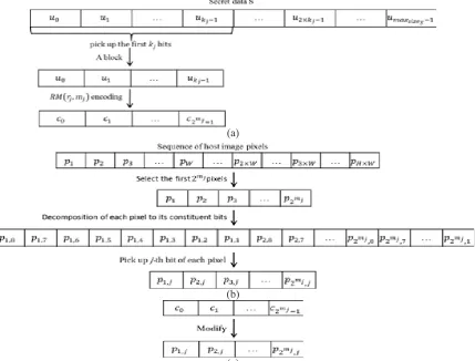
low-order bit from pixels of the image by RM(rj,mj) . For example, Fig. 3 shows an encoding process for the first information block and modifying values of the first block (qj=1) of the host image. After modifying values of all blocks of the host image, we consider modified the decimal form of the low-order bits from pixels of I as an image and we name this image S`. Values of S` will be in the range of 0 to 2n−1. Finally, we use the method explained in section (2-2) to embed information. Embedding algorithm is presented step by step as follows.
Data Embedding Process
Input: A grayscale image (I) with the size of H×W which is
used as a host image, secret binary data S, the number of the used low-order bits (n), block code RM(rj,mj) for encoding data of S to substitute j -th low-order bit of the host image blocks.
Output: A stego image (I`) with the size of H×W.
Step 1: scan pixels of image I (pi,1≤i≤H×W) from top to
bottom and left to right.
Step 2: For embedding blocks in j -th low-order bit, divide
sequence of pi to nb block b(qj) by the length of 2mj where and 1≤qj≤nb.
Step 3: Consider the initial value of qj equal to 1.
Step 4: Decompose values of pixels of the block b(qj) to its
constituent bits. Take j -th low-order bit of each pixel and name sequence of these bits .
Step 5: Reed kj next bit ( ) where .
Step 6: Encode a sequence of the bits obtained from the
previous step (u(qj)) using encoder RM(r
j,mj) described in section 3-2, and name sequence of the encoded bits c(qj).
Step 7: Modify bits of the block to bits of the block c(qj).
Step 8: Increase qj to one unit and return to step 4 until qj<nb.
Step 9: Consider the modified decimal form of the low-order
bits from pixels of I as an image S`.
Step 10: Considering a new image S`, compute di and d`i from
Eq. (1) and (2), respectively where 1≤i≤H×W.
Step 11: Compute the modified value of gray level of i -th
pixel of the image I after embedding process ( ) from Eq. (3) to obtain stego image.
B. Extraction Process
Since the designed algorithm is a blind steganography technique, here, we will not need original image. Assuming that receiver is aware of Reed-Muller code parameters (i.e. rj and mj), secret data will be extracted by the algorithm which is explained in the following. We name pixels of stego image where i =1,2,...,H×W. By applying Eq. (4) on pixels of received stego image, we first obtain the values which have been hidden into n low-order bits of pixel (i.e. xi s). Now, the information is ready for being decoded by Reed decoder. To decode the information hidden in j -th low-order bit, we first divide modified pixels sequence of the image ( ) to nb block b(qj) with length of 2mj where and
1≤qj≤nb . After decomposing pixels of each block to its 8 constituent bits, we pick up j -th low-order bit from pixels of each block b(qj) and form a sequence of bits in the form of (a)
(b)
(c)
Fig. 3. Encoding process for the first information block and modifying values of the first block (qj=1) of host image:
(a) generating the first information block, (b) generating the first host image block, (c) modifying.
2
×
=
j
b H Wm n
( )
qj binaryp
1 2
= ( ) ( ) ( )( )
( )
u j j , j , , j q j
q q q
q
k
u u u
0 =
=
∑
rj jj i m
k
i
( )
qj binaryp
ˆi
y
ˆi
y
ˆi
y
ˆi
y
2
× = j
b H Wm
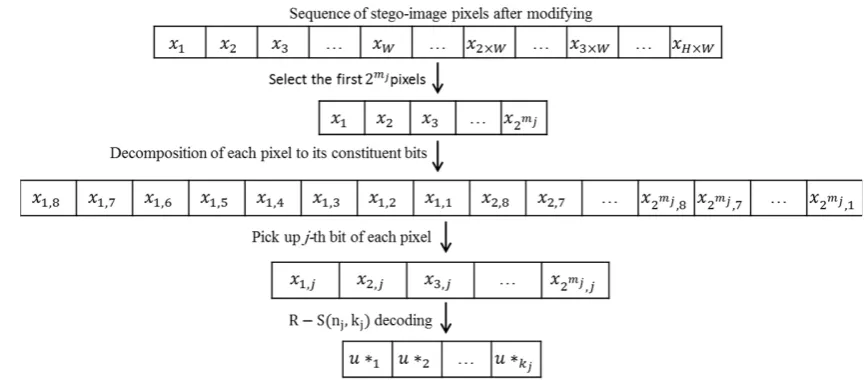
Each block x(qj), after decoding process by the method explained in section 3-3, generates a kj -bit sequence in the form of
which is obtained from the relation . Fig. 4, for example, shows decoding process of the first modified block and extraction of its first secret block (qj=1). Extraction algorithm is presented step by step as follows.
Data Extraction Process
Input: A stego image (I`) with the size of H×W, the number
of the used low-order bits (n), block code RM(rj,mj) for decoding secret data embedded in blocks of the host image.
Output: Secret data.
Step 1: For pixels of image I`(i=1,2,...,H×W), apply Eq. (4) to obtain xi (the hidden value into n -th low-order bit of pixel ).
Step 2: For decoding information available in the j -th
low-order bit, divide values sequence of xi into nb blocks b(qj) by a length of 2mj where and 1≤qj≤nb .
Step 3: Consider the initial value of qj equal to 1.
Step 4: Decompose values of the block b(qj) to its constituent
bits. Pick up the j -th low-order bit of each block and name sequence of these bits x(qj) .
Step 5: Decode sequence of the bits obtained from the
previous step using Reed decoder which was described in section 3-3 and name kj -bit decoded sequence u*(qj).
Step 6: Increase qj to one unit. Until information of all blocks is extracted, return to step (4).
5- Simulation Results And Discussion
To evaluate the performance of the proposed method, we considered nine grayscale images with a size of 512×512 as test images and compared our method with other methods by three quantitative measures.
Visual quality is usually evaluated by PSNR criterion which shows a degree of difference between original image and stego image in dB and calculated from the following relation:
In the above relation, MSE indicates the difference between values of pixels in the original image and stego image and is defined as In this relation, H and W are length and height of the image, respectively. Iij are pixels value of the original image and I`ij are pixels value of stego image. The lower the difference between two images, the lower the MSE value and as a result, the higher the PSNR value which is more desirable for goals of steganography.
The second criterion is embedding payload which is the ratio of the number of bits embedded in host image to the number of pixels of host image and is defined as:
where |S| refers to the number of secret bits which are carried by host image. The payload is measured in bits-per-pixel (bpp). The third criterion is error correction which enables the user to retrieve the secret information which has been destroyed in case of intentional or unintentional destruction of stego image. Error correction capacity is defined as:
where bc and be are the number of correct bits and the number of error bits after extraction process, respectively.
A change in more significant bits causes more visual distortion and it is necessary that information extraction module in more significant bits have a better error correction performance than that in less significant bits. Therefore, we used RM(1,3) and RM(2,5) for embedding information into the first and second bits of pixels from the right side, respectively which are able to correct 3 and 7 error bits considering Eq. (7). The secret data type used in the simulations has been textual that we convert it into binary data using ASCII codes, initially. Each one of the test images carries 393216 bits of information. Fig. 5 shows some visual results of simulations by the proposed method. In the left column, original images are observed. Middle and right columns show the images embedded by the proposed method and images destroyed by different attacks, respectively. In Table 1, a comparison between the proposed method and the other techniques is performed in terms of
( ) ( ) ( ) ( )
( )
1, , 2, , 3, ,..., 2 ,
=
x j j j j j
m j
q q q q
q
j j j j
x x x x
( ) ( ) ( ) ( )
* * * *
1 2
u = , ,..., qj qj qj qj
j k
u u u
0 =
=
∑
rj jj i m
k
i
ˆi
y
2
×
=
j
b H Wm n
Fig. 4. Decoding process of the first modified block and extraction of its first secret block (qj=1).
2 10 255
10log =
PSNR
MSE (18)
(19)
(20)
' 2
1 1
1 ( )
= =
= −
×
∑ ∑
H W
ij ij
i j
MSE I I
H W
= ×
S P
H W
= c
e
b C
visual quality and embedding payload in stego image. The maximum payload in the methods of [30], HCIH [19] and HQIH [19] is 1 bit per pixel, while the proposed method is capable of carrying data with a payload greater than 1 bit per pixel, with preserving visual quality. In a compromise between payload and visual quality, the proposed method is competitive with methods [18] and [20]. Although method [21] shows better results, it is not robust against the attacks. Comparison results between the proposed method and the method [30] are given in Table 2. The results show the proposed method guarantees PSNR of above 48.1 dB while the embedding payload is increased by 50% compared with method [30]. Also, the proposed method has increased error correction capacity against all kinds of noises with different intensities and statistical characteristics. We also compared the robustness of the proposed algorithm, algorithm [31]
and algorithm [30] against adding salt and pepper noise with different densities. The obtained results are listed in Table 3. As can be seen, the proposed method shows a great robustness compared with the other two methods.
6- Conclusions
A blind steganography scheme with a high embedding payload was presented. Although our method is able to embed information into more significant bits, it preserves visual quality of image well. The obtained results from the simulations were compared with studies [18], [19], [20], [21], [30] and [31]. While we increased embedding payload, it led to PSNR of more than 48.1 dB. In addition, we increased robustness against noise and filtering attacks using Reed-Muller error correction code and as a result of increasing error correction capacity.
Test Images The method [30] The method [18] (r=5) The method [18] (r=6) The method HCIH [19] The method HQIH [19] The method [20] The method SOS [21] The proposed method Test
Image Image Name PSNR (dB) (bpp)P PSNR (dB) (bpp)P PSNR (dB) (bpp)P PSNR (dB) (bpp)P PSNR (dB) (bpp)P PSNR (dB) (bpp)P PSNR (dB) (bpp)P PSNR (dB) (bpp)P
Jet
(F16) 50.77 0.99 45.25 1.97 51.15 1.00 46.01 0.75 52.10 0.83 46.87 0.64 49.88 1.58 48.24 1.50
Lena 50.84 0.99 45.14 1.99 51.14 1.00 47.02 0.75 52.09 0.83 46.86 0.64 49.89 1.58 48.12 1.50
Pepper 50.12 0.99 45.77 1.80 51.15 1.00 45.12 0.75 52.10 0.83 46.86 0.64 49.88 1.58 48.15 1.50
Zellda 51.14 0.99 45.13 2.00 51.14 1.00 45.38 0.75 52.10 0.83 46.85 0.64 49.88 1.58 48.13 1.50
Average 50.72 0.99 45.32 1.94 51.15 1.00 45.88 0.75 52.10 0.83 46.86 0.64 49.88 1.58 48.16 1.50 Table 1. A comparison between the proposed method and the other techniques in terms of visual quality and embedding payload.
Table 2. Comparison results between the proposed method and the method [1]
The method [30] The proposed method
Image Image name PSNR P Attack (Destroyed)PSNR C PSNR P Attack (Destroyed)PSNR C
Baboon 50.96 0.99 Gaussian noise: mean 0
& variance 0.01 20.05 1.00 48.13 1.50
Gaussian noise: mean 0 &
variance 0.01 20.03 1.20
Barbara 50.36 0.99 Gaussian noise: mean 0
& variance 0.1 11.45 1.01 48.14 1.50
Gaussian noise: mean 0 &
variance 0.1 11.48 1.21
Boats 50.39 0.99 Salt & Pepper noise:
density 0.05 18.53 17.49 48.14 1.50
Salt & Pepper noise:
density 0.05 18.52 198.10
Goldhill 51.09 0.99 Salt & Pepper noise:
density 0.5 8.12 1.91 48.14 1.50
Salt & Pepper noise:
density 0.5 8.12 2.15
Lena 50.84 0.99 Speckle noise: variance
0.04 19.77 0.99 48.12 1.50
Speckle noise: variance
0.04 19.74 1.22
Pepper 50.12 0.99 Speckle noise: variance 0.4 10.80 0.99 48.15 1.50 Speckle noise: variance 0.4 10.77 1.19
Tiffany 51.15 0.99 Median filter 31.06 1.41 48.14 1.50 Median filter 31.04 1.47
Zellda 51.14 0.99 Gaussian low-pass filter: sigma 0.9 37.30 0.99 48.13 1.50 Gaussian low-pass filter: sigma 0.9 37.28 1.21
References
[1] W. Zeng, Digital watermarking and data hiding: technologies and applications, in: Proc. Int. Conf. Inf. Syst. Anal. Synth, 1998, pp. 223-229.
[2] M. Wu, B. Liu, Data hiding in image and video. I. Fundamental issues and solutions, Image Processing, IEEE Transactions on, 12(6) (2003) 685-695.
[3] M. Wu, H. Yu, B. Liu, Data hiding in image and video. II. Designs and applications, Image Processing, IEEE Transactions on, 12(6) (2003) 696-705.
[4] C.-T. Wang, H.-F. Yu, A Markov-based reversible data hiding method based on histogram shifting, Journal of Visual Communication and Image Representation, 23(5) (2012) 798-811.
[5] X. Zhang, S. Wang, Vulnerability of pixel-value differencing steganography to histogram analysis and modification for enhanced security, Pattern Recognition Letters, 25(3) (2004) 331-339.
[6] H.V. Desai, Steganography, Cryptography, Watermarking: A Comparitive Study, Journal of Global Research in Computer Science, 3(12) (2013) 33-35.
[7] J. Dittmann, P. Wohlmacher, K. Nahrstedt, Using cryptographic and. watermarking algorithms, Multimedia, IEEE, 8(4) (2001) 54-65.
[8] A. Abbass, E. Soleit, S. Ghoniemy, Blind video data hiding using integer wavelet transforms, Ubiquitous Computing and Communication Journal, (2007).
[9] Y. Wang, A. Pearmain, Blind image data hiding based on self reference, Pattern Recognition Letters, 25(15) (2004) 1681-1689.
[10] X.-Y. Luo, D.-S. Wang, P. Wang, F.-L. Liu, A review on blind detection for image steganography, Signal Processing, 88(9) (2008) 2138-2157.
[11] H. Yang, X. Sun, G. Sun, A high-capacity image data hiding scheme using adaptive LSB substitution, Radioengineering, 18(4) (2009) 509.
[12] R.-Z. Wang, C.-F. Lin, J.-C. Lin, Image hiding by optimal LSB substitution and genetic algorithm, Pattern recognition, 34(3) (2001) 671-683.
[13] C.-C. Thien, J.-C. Lin, A simple and high-hiding capacity method for hiding digit-by-digit data in images based on modulus function, Pattern Recognition, 36(12) (2003) 2875-2881.
[14] C.-C. Chang, C.-S. Chan, Y.-H. Fan, Image hiding scheme with modulus function and dynamic programming strategy on partitioned pixels, Pattern Recognition, 39(6) (2006) 1155-1167.
[15] A.D. Ker, Steganalysis of LSB matching in grayscale images, Signal Processing Letters, IEEE, 12(6) (2005) 441-444.
[16] J. Mielikainen, LSB matching revisited, Signal Processing Letters, IEEE, 13(5) (2006) 285-287.
[17] D.-C. Wu, W.-H. Tsai, A steganographic method for images by pixel-value differencing, Pattern Recognition Letters, 24(9) (2003) 1613-1626.
[18] H. Yang, X. Sun, G. Sun, A High-Capacity Image Data Hiding Scheme Using Adaptive LSB Substitution, Radioengineering, 18(4) (2009).
Barbara PSNR=48.14 & P=1.5 PSNR=11.48 & C=1.21
Goldhill PSNR=48.14 & P=1.5 PSNR=8.12 & C=2.15
Papper PSNR=48.15 & P=1.5 PSNR=10.77 & C=1.19
Zellda PSNR=48.13 & P=1.5 PSNR=37.28 & C=1.21
(a) (b) (c) Fig. 5. Some visual results of simulations by the proposed method: (a) host images, (b) stego images with payload 1.5 bpp and (c) stego images destroyed by various attacks (from top to bottom, respectively: Gaussian noise with mean 0 & variance
0.1, Salt & Pepper noise with density 0.5, Speckle noise with variance 0.4 and Gaussian low-pass filter with sigma 0.9).
Table 3. A comparison between the proposed method and the method [31] and [30] in terms of robustness against adding salt
and pepper noise with different densities.
Image DensityNoise
The method
[31]
The method
[30]
The proposed
method
C C C
Girl
(Elaine) 0.005 26.59 173.99 12287 0.007 18.40 125.21 8191
0.01 13.45 88.62 4467
0.02 8.23 43.00 1585
Lena 0.005 19.22 185.97 24576 0.007 15.09 128.90 9829
0.01 12.76 85.06 8191
[19] Y. Zhang, J. Jiang, Y. Zha, H. Zhang, S. Zhao, Research on Embedding Capacity and Efficiency of Information Hiding Based on Digital Images, International Journal of Intelligence Science, 3 (2013) 77.
[20] B. Jena, High payload digital image steganography using mixed edge detection mechanism, 2014.
[21] Z.-X. Yin, C.-C. Chang, Q. Xu, B. Luo, Second-order steganographic method based on adaptive reference matrix, IET Image Processing, 9(4) (2015) 300-305. [22] X. Zhang, S. Wang, Efficient steganographic
embedding by exploiting modification direction, IEEE Communications Letters, 10(11) (2006) 781-783.
[23] C.-C. Chang, Y.-C. Chou, T.D. Kieu, An information hiding scheme using Sudoku, in: Innovative Computing Information and Control, 2008. ICICIC’08. 3rd International Conference on, IEEE, 2008, pp. 17-17. [24] W. Hong, T.-S. Chen, C.-W. Shiu, A minimal Euclidean
distance searching technique for Sudoku steganography, in: 2008 International Symposium on Information Science and Engineering, IEEE, 2008, pp. 515-518. [25] R.-M. Chao, H.-C. Wu, C.-C. Lee, Y.-P. Chu, A novel
image data hiding scheme with diamond encoding, EURASIP Journal on Information Security, 2009(1) (2009) 1.
[26] Z. Yin, B. Luo, MDE‐based image steganography with large embedding capacity, Security and Communication Networks, (2015).
[27] R. Crandall, Some notes on steganography, Posted on steganography mailing list, (1998).
[28] A. Westfeld, F5—a steganographic algorithm, in: Information hiding, Springer, 2001, pp. 289-302.
[29] W. Zhang, S. Wang, X. Zhang, Improving embedding efficiency of covering codes for applications in steganography, Communications Letters, IEEE, 11(8) (2007) 680-682.
[30] C.-C. Chang, T.D. Kieu, Y.-C. Chou, A high payload steganographic scheme based on (7, 4) hamming code for digital images, in: Electronic Commerce and Security, 2008 International Symposium on, IEEE, 2008, pp. 16-21.
[31] S. Singh, T.J. Siddiqui, A Security Enhanced Robust Steganography Algorithm for Data Hiding, International Journal of Computer Science Issues (IJCSI), 9(3) (2012). [32] S.B. Wicker, Error control systems for digital
communication and storage, Prentice hall Englewood Cliffs, 1995.
[33] L. Shu, S. Lin, D.J. Costello, Error control coding, Pearson Education India, 2004.
Please cite this article using:
A. M. Molaei, M. H. Sedaaghi, H. Ebrahimnezhad,”Steganography Scheme Based on Reed-Muller Code with Improving Payload and Ability to Retrieval of Destroyed Data for Digital Images”, AUT J. El ec. Eng., 49(1) (2017)53-62.