Iranian Journal of Electrical and Electronic Engineering, Vol. 15, No. 4, December 2019 434
Design of Monophasic Spike-Exponential Waveform for
Functional Electrical Stimulator Based on Pulse Width
Modulation
A. P. Hutomo*, I. P. Buditomo*, A. P. Putra**, S. Suhariningsih***, and S. D. Astuti*,***(C.A.)
Abstract: The Functional Electrical Stimulator design using monophasic spike-exponential waveform was proposed and described in this study. The monophasic square waveform has benefit in generating an action potential, but it could cause side effects such as toxic caused by the electrode polarization. The square waveform signal which the frequency and pulse width could be modulated was manipulated to be the monophasic spike-exponential waveform. Transformer OT240 was applied at the end of the FES system part and functioned as a voltage amplifier and DC signal isolator. On every frequency range between 5–100 Hz, the 16 peak voltage stages with the lower limit of 45 Volt and an upper limit of 400 Volt was arranged to obtain VRMS value in each stage. Characterization result shows that the produced waveform was monophasic spike-exponential with the narrow pulse width (t1/2 = 7 µs) and VRMS in the maximum frequency and peak voltage was
8.99 Volt. This study showed that the designed FES had high VP and low VRMS, thus, it could be concluded that this FES system design could be a candidate for its application.
Keywords: Functional Electrical Stimulation, Medical Rehabilitation, Monophasic Spike-Exponential Waveform, Pulse Width Modulation.
1 Introduction1
UNCTIONAL Electrical Stimulation (FES), compared to conventional therapy, is a technology that potentially providing more efficient, cost-effective therapy, enabling more frequent practice of movement and increased motivation [1]. It works based on artificial muscular contraction induced by a train of electrical stimuli [2, 3]. It applies low-stage electrical
Iranian Journal of Electrical and Electronic Engineering, 2019. Paper first received 26 December 2018, revised 27 April 2019, and accepted 06 May 2019.
* The authors are with the Biomedical Engineering Department, Postgraduate School, Universitas Airlangga, Surabaya 60286, Indonesia.
E-mails: [email protected] and [email protected]. ** The author is with the Biomedical Engineering Study Program, Department of Physics, Faculty of Science and Technology, Universitas Airlangga, Surabaya 60115, Indonesia.
E-mail: [email protected].
*** The authors are with the Department of Physics, Faculty of Science and Technology, Universitas Airlangga, Surabaya 60115, Indonesia.
E-mails: [email protected] and
[email protected]. Corresponding Author: S. D. Astuti.
current in few milli-amperes either to the nerves control that muscles nerves or directly over the motor end-plate [4]. This electrical stimulation facilitates the reorganization of neuromuscular activity [5] and augments the neuronal excitability of sensory motor cortex [6, 7], also recover motor function [8-9]. It is shown as one of the most effective therapeutic modalities for improving voluntary movement in many kinds of disease supported by clinical studies such as stroke [10–12]; ankle foot injury [13]; hemiplegia [14]; denervated human muscle [15]; and hypertonicity [16]. On the other hand, the outcome of FES-based rehabilitation still involves some manual assistance by a physiotherapist to perform functional task concurrently with the application of electrical stimulation [17, 18]. The intensity stimulation of FES is delivered as the waveform of electrical current pulses, which are defined as a function of the total charge transferred to the muscle which depends on pulse duration, amplitude, and frequency [19, 20]. Pulse duration is also known as pulse width or the stimulus time per cycle, while the current amplitude is the peak current value in the phase delivered by each pulse, both produce the amount of ionic flow to trigger action potentials that control the
F
Iranian Journal of Electrical and Electronic Engineering, Vol. 15, No. 4, December 2019 435
strength of muscle contraction[21, 22]. Stimulation frequency is also called the pulse rate, another important feature of electrical stimulation, controls the type of muscle contraction and the amount of produced [23]. Some numbers have shown the different application of each pulse parameter on clinical assessment [24-26]. Thus, three kinds of waveform parameter are together combined and need to be set to determine the success of therapy [27].
Due to the better action potential generation, monophasic is better than others [28]. Monophasic square is the most common waveform that has been already applied clinically and gives a satisfying result in any kinds of FES therapy [29-31]. However, monophasic square has some side effects, such as electrode corrosion that can be toxic [28], skin burns, muscle fatigue, and tissue damage during its polarization [32, 33] and those are caused by the high root mean square voltage (VRMS). In square waveform, the value of peak voltage (VP) is similar to VRMS. Therefore, the square waveform is undesirable because the severity of its side effects will be higher when the VP is higher. Whereas the high VP is needed due to the successful therapy. Thus, stimulated signal modulation is needed to obtain the optimum intensity and pulse parameter setting, while at the same time, preventing its side effects [33-36].
In this study, we present the design of monophasic spike-exponential waveform FES which has a relatively narrow pulse width. The advantage of the monophasic spike-exponential waveform is having less VRMS than VP, resulting in smaller root mean square current (iRMS). In order to control the big peak voltage of the monophasic spike-exponential waveform, pulse-width modulation is applied by using an occupied microcontroller. Direct current (DC) signal block is used to ensure that there is no polarization around the electrode.
2 Methods
2.1 Block Diagram
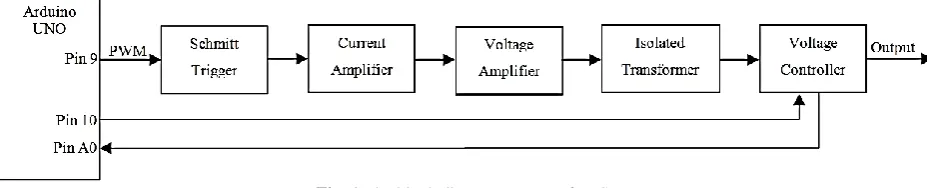
In this system, the generation of the monophasic spike-exponential waveform is begun within the generation of square wave signal which is pulse width and frequency can be controlled by pin 9 on Arduino UNO. Schmitt trigger is applied to ensure that the square wave signal is perfectly generated. In order to
obtain the signal that can control the voltage amplifier circuit in form of the controllable transformer by the power transistor, the output of the Schmitt trigger is connected to the current amplifier. Besides the voltage amplifier, the transformer can be functioned as DC signal isolator. The transformer’s output will be controlled by the voltage controller. Voltage controller consists of a voltage divider circuit in which each output voltage connected to the relay driver and multiplexer circuit control which one of driver relay is active. Arduino UNO controls the voltage stage which increases every two seconds by pin 10. Once the voltage stimulus matched with the therapeutic needs, press the push button that connected to pin A0 to lock then start the therapy process. The block diagram system of FES is shown in Fig. 1.
2.2 Instrumental Design
The square pulse width is controlled in order to obtain the desired amplitude of the monophasic spike-exponential waveform. In this design, the desired amplitude is 400 Volt generated by controlling the pulse width, so that each frequency has a different square pulse width.
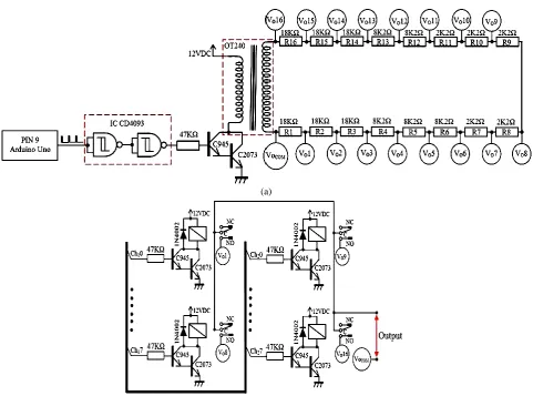
Based on the electrical circuit we used in this study, in order to generate the narrow pulse width of the monophasic spike-exponential waveform, notably, the perfect square exponential is needed. Schmitt trigger is applied to ensure that the perfect square waveform signal was generated. In this design, the NAND logic gate is applied together with the Schmitt trigger. Thus, the applied combination of these two components gives simplicity than using the others, where other components are still needed. The circuit schematic of FES which can generate monophasic spike-exponential waveform is shown in Fig. 2.
In order to get the generated small current from NAND and Schmitt trigger, a 47KΩ resistor is used, resulting in guaranteed endurance and stability. On the other hand, it can be done because Darlington of the current amplifier transistor arrangement doesn’t need bigger current on transistor’s base, thus the Darlington circuit in this system can be also called as a current amplifier. The OT240 voltage amplifier will be controlled by two NPN transistors in the Darlington circuit. In order to amplify the voltage, the transformer OT240 will be functioned as a step-up transformer. The
Fig. 1 The block diagram system of FES.
Iranian Journal of Electrical and Electronic Engineering, Vol. 15, No. 4, December 2019 436 (a)
(b)
Fig. 2 a) Circuit schematic of FES that generates a monophasic spike-exponential waveform, and b) Relay driver circuit of FES.
OT240 transformer is functioned as both voltage amplifier circuit and DC signal isolator. Researchers have shown that isolating DC signal can help to prevent body polarization, thus the safety can be guaranteed [28, 37]. Sixteen resistors are installed serially on the OT240 transformer output which is functioned as a voltage divider, where each output voltage is connected to the relay. The relay driver circuit is shown in Fig 3. The multiplexer is used to control relay driver, thus, it can be determined which one the active relay is. 3-bit of IC CD4051 multiplexer is used and it controls the 8 different sequences. 4-bit multiplexer can be obtained by combining two IC CD4051 multiplexer and controlling the voltage stage (high and low) on pin INH, A, B, and C, resulting in the production of 16 sequences. The truth table of 4-bit multiplexer by combining two IC CD4051 is shown as Table 1.
2.3 Data Retrieving
All signal parameters are measured using an oscilloscope (Atten ® Instruments AT 7340 40MHz),
including signal form, amplitude (VP), frequency (f), and half-life (t1/2). The same oscilloscope is also used
Table 1 Truth table of 4-bit multiplexer by combining two IC CD4051.
Input States “ON” Channel (s) Voltage Stage
INH A B C
0 0 0 0 Ch10 0
0 0 0 1 Ch11 1
0 0 1 0 Ch12 2
0 0 1 1 Ch13 3
0 1 0 0 Ch14 4
0 1 0 1 Ch15 5
0 1 1 0 Ch16 6
0 1 1 1 Ch17 7
1 0 0 0 Ch20 8
1 0 0 1 Ch21 9
1 0 1 0 Ch22 10
1 0 1 1 Ch23 11
1 1 0 0 Ch24 12
1 1 0 1 Ch25 13
1 1 1 0 Ch26 14
1 1 1 1 Ch27 15
Note: Ch10–Ch17 are output channel in the IC CD4051 (1) and Ch20 – Ch27 are output channel in the IC CD4051 (2).
Iranian Journal of Electrical and Electronic Engineering, Vol. 15, No. 4, December 2019 437
to measure the output voltage stability. The stability test is done by using 15 kΩ of the resistor which is applied in the electrode.
2.4 Body Resistance Measurement
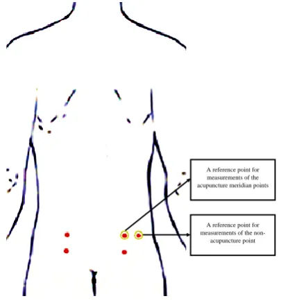
The measurement of body resistance was performed on 5 volunteers at acupuncture meridian and non-acupuncture point with a distance of 5 cm and 10 cm. there were 5 replications of this measurement. The measurement at acupuncture meridian was at urinary bladder meridian. Fig. 3 showed the reference point at acupuncture meridian and non-acupuncture point. The yellow circle at Fig. 3 was the reference point for body resistance measurement. At acupuncture meridian, the reference point was BL48 and at non-acupuncture point, the reference point was on the right of acupuncture point with a distance of 5 cm.
3 Results and Discussion
This FES system design begins with the signal square which is generated by controlling Arduino UNO’s timer/counter port, so both pulse width and frequency can be desirably controlled. In order to achieve this system requirement, the square waveform signal modulation is applied and called as PWM, so this design does not need the DAC circuit. Generating 400 Volt monophasic spike-exponential waveform VP can be achieved by controlling PWM on each frequency. On the other hand, every voltage controller on each frequency is given the same value VP. The PWM value on each frequency is shown in Fig. 4.
The FES system design is conditionally staged, it can start from lower to higher voltage stage, so the
A reference point for measurements of the
non-acupuncture point A reference point for measurements of the acupuncture meridian points
Fig. 3 The reference point position for body resistance measurement.
stimulation voltage can be adjusted according to the needs of patients. Thus, the patient who is under electrical stimulation can feel the comfort with no pain. Voltage controller of this FES is controlled by the 4-bit multiplexer, so the 16 voltage stages with the lower limit of VP(1) = 45 Volt and an upper limit of VP(16) =
400 Volt are obtained. Fig. 5 shows the increasing voltage on each stage. The stimulation voltage is expected to be approximately 200 Volt, so between VP(6) = 197 to VP(11) = 224 Volt, the voltage
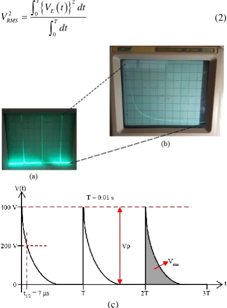
increasing needs to be smoothed. Overall, the adjustment of the voltage increasing on every stage is required because there are only 16 stages in this FES system design. In order to determine every VRMS stage on each frequency, the FES voltage output is arranged. Thus, it can be predicted how much FES iRMS is used. Fig. 6 shows the waveforms produced by FES. Based on this image, it can be proven that the system design has succeeded in producing a monophasic spike-exponential waveform. These waves are more desirable
Fig. 4 The graph of required PWM value at each frequency to achieve VP = 400 Volt.
Fig. 5 Stage of voltage increment for each amplitude (VP).
Iranian Journal of Electrical and Electronic Engineering, Vol. 15, No. 4, December 2019 438
as output from FES due to higher VP and lower VRMS production. The reason behind this can be explained through the physical concept of electric waves. Basically, electrical stimulation therapy is giving stimulation from the electrical current train from the stimulator to the patient’s body [2, 3]. During the electrical stimulation, iRMS is proportional to its VRMS and inversely proportional to the resistance or impedance of the human body [38]. In order to increase the therapy effectiveness, high voltage stimulation (in the meaning of its potential differences) is required. Besides, to fulfill the medical safety standard, the value of iRMS must be less than 5 mA [39].
In order to fulfill the therapy requirements, the monophasic spike-exponential waveform is chosen as the output signal, due to its high VP and at the same time, low iRMS. In other words, the VP of the monophasic spike-exponential waveform is higher than VRMS. The mathematical equation of monophasic spike-exponential waveform voltage between t = 0 until t = T is described as
( ) t
E P
V t V e (1)
where 𝜆 is a constant that represents the voltage exponential decreasing. The magnitude of exponential root means square voltage signal can be described as:
22 0
0
T
E
RMS T
V t dt
V
dt
(2)(c)
Fig. 6 The generated monophasic spike-exponential waveform
of designed FES as shown using 5 Volt/div, X10 probe with a) 2 ms/div, and b) 10 µs/div. c) The illustration of monophasic spike-exponential waveform unit characteristics.
2 2 2
0
1 T t
RMS P
V V e dt
T
(3)
2
2 1 2
2 T P RMS V V e T
(4)
2 1 2 T P RMS V V e T
(5)
Completely, the unit characteristic of monophasic spike-exponential were illustrated in Fig. 6(c). An important quantity on exponential function is half-life (t1/2). Half-life can be described as the begin
time (t = 0) until the reached time that the voltage value becomes a half from the beginning voltage. The relation between 𝜆 and t1/2 can be described as:
1/2 2 t P P V
V e
(6)
1/ 2
0.693
t
(7)
Substituting 𝜆 on (7) to the (5), Eq. (8) can be obtained
1/21.386 1/ 2 1 1.386 T t P RMS V V e T t
(8)
T >> t1/2 cause VRMS becomes
1/ 2 1.177 P RMS t V V T (9)
Equation (9) is substantial in the study about FES using monophasic spike-exponential waveform because it clearly represents how VRMS corresponds. The stage arrangements of the stimulation voltages give advantage on knowing VRMS on each stage so that iRMS can be obtained when the impedance value of the patient’s body [40] between two electrodes is known. In this study, the impedance on the body surface between the two electrodes is assumed to be 15–20 kΩ [41]. Based on the characteristic result showed in Figure 6, the t1/2 of
FES on the frequency of 5-100 Hz is 7 µs. On the other hand, at the highest frequency of 100 Hz and the maximum VP of 400 Volt, the VRMS is obtained as
8.99 Volt. The FES output current of around 0.6 mA is still far below the human pain threshold, which is 5 mA [39], thus the FES designed in this study can be classified as safe, not harmful, and comply the medical regulations. The monophasic spike-exponential waveform has a very narrow pulse width, so it can reduce the risk of muscle fatigue [42-44]. Every stage of VRMS on each frequency is shown in Fig. 7.
In clinical practice, therapy using FES [45, 46] is done by applying two electrodes on the patient’s body [47, 48]. The FES flows electrical current from the positively charged electrode to the negatively charged electrode. Thus, potential differences (V) are induced between two FES electrodes and therefore increasing
Iranian Journal of Electrical and Electronic Engineering, Vol. 15, No. 4, December 2019 439
the potential energy (Ep) of charged particle (q) on the patient’s body. It has been well-known that there are many kinds of ions in the human body [38] that has the electrical function as the electrically charged particle and has a certain mass (m) which is always moved [38]. The increasing electrical potential energy on the particle has a speed increasing potency (u) of electrically charged particle’s movement. Due to the constant particle charge and mass, the change of particle movement speed is proportioned with the given potential roots square difference.
The mechanism of the speed increase of charged particle movement speed can be explained using electrical force concept. Potential differences between two points separated by a distance (d) causing electrical field generation (E = V⁄d). Charged particle q which is in influenced electrical field E, has the electric force by the amount of F = qE. Electric force gives particle movement acceleration effect (a = F⁄m), thus particle movement acceleration is proportional to the electric potential differences that are given and inversely proportional to the differences between the two applied electrodes.
Fig. 7 Every stage of VRMS on each frequency.
Fig. 8 The stability testing of the designed FES voltage output on each frequency.
Due to the testing on each frequency, which is done by 1-minute measurement for 30 minutes, the created FES system design has good voltage stability which were shown in Fig. 8 Every minute measurement which is done by applying 15KΩ assessment shows that the FES peak voltage is stable due to the 400 Volt peak voltage. The FES system design with this monophasic spike-exponential waveform output is already able to show VRMS at each frequency and stage. This FES system design needs to be improved by adding a system of the body’s impedance measurement between two electrodes, so the iRMS that flow directly to the body can be determined. As a result, the appropriate therapeutic dose can be obtained.
The measurement of body resistance was performed at acupuncture meridian and non-acupuncture point based on Fig. 3 with a distance of 5 cm and 10 cm. the result of this measurement was shown in Fig. 9. Fig. 9 showed that the distance between two linear electrodes was correlated to the body resistance. The further the
(a)
(b)
Fig. 9 The body resistance of 5 volunteers (A, B, C, D, and E) at acupuncture meridian and non-acupuncture point with a
distance of 5 cm and 10 cm.
Iranian Journal of Electrical and Electronic Engineering, Vol. 15, No. 4, December 2019 440
resistance value at the acupuncture meridian was lower than the non-acupuncture point.
The use of FES for stimulating the nervous stem through tripolar cuff electrodes could cause delay in muscle fatigue. Thus, the design of hyperpolarization pulse with ramp structure at the pulse termination could prevent the Anode-Break Excitation (ABE) phenomenon. ABE is an electrophysiological phenomenon in which the neurons fire the action potential as a response towards hyperpolarization current termination. So, FES with Monophasic Spike-Exponential waveform would be beneficial if it is used to stimulate the nervous stem directly. Because of that, the stimulator output impedance, heart rate amplitude resolution, and the resistance used as the load could be suitable with that waveform. Muscle activation that is induced by non-physiological had a crucial demarcation which was the decrease of contraction and tendency to have muscle fatigue. By using functional electrical stimulator, the muscle fatigue could be reduced and improve the output by tailoring the parameters of the stimulation. It is important for patient safety and the success of the treatment to determine the stimulation settings. Several parameters hat should be taken into account are the frequency, duty cycle, ramp time, pulse width, pulse pattern, intensity, and the desired muscle group [34].
Another study of FES showed that the skin resistance on the acupuncture point could be higher or lower compared to the surrounding area. The acupuncture point might be have a specific temporary electrical properties. Kramer et al (2009) study mentioned that most of the acupuncture point did not show a change in electrical skin resistance [49].
4 Conclusion
FES system design which has been made can generate the monophasic spike-exponential waveform with the frequency between 5-100 Hz which has an advantage of narrow pulse width (t1/2 = 7µs). It can prevent muscle
fatigue because of high VP but small VRMS, so that small iRMS will be generated. It makes FES system design safe to be used because in the highest frequency (100 Hz) and VP (400 Volt), iRMS is generated by the value of 0.6 mA or under the medical safety standard. Besides that, FES system is applied by output voltage controller of stages arrangement. Thus every VRMS stages on each frequency can be measured, so the iRMS value flown to the body can be easily predicted. Moreover, this system has good output voltage stability, so this FES can be applied clinically as a medical rehabilitation tool due to its effective, safe, and comfortable application.
References
[1] O. Brend, C. Freeman, and M. French, “Multiple-model adaptive control of functional electrical stimulation,” IEEE Transactions on Control Systems Technology, Vol. 23, No. 5, pp. 1901–1913, Sep. 2015.
“Intensive training of subjects with chronic hemiparesis on a motorized cycle combined with functional electrical stimulation (FES): A feasibility and safety study,” Physiotherapy Research International, Vol. 16, No. 2, pp. 81–91, Jun. 2011.
[3] E. Peri, E. Ambrosini, A. Pedrocchi, G. Ferrigno, C. Nava, V. Longoni, M. Monticone, and S. Ferrante, “Can FES-augmented active cycling training improve locomotion in post-acute elderly stroke patients?,” European Journal of Translational Myology, Vol. 26, No. 3, pp. 187–192, 2016.
[4] T. C. Vinil, S. Devasahayam, G. Tharion, and B.P.Naveen, “Investigation of controllable multi electrode based FES (functional electrical stimulation) system for restoration of grasp-preliminary study on healthy individuals,” IEEE Global Humanitarian Technology Conference-South Asia Satellite (GHTC-SAS), pp. 212–215, 2014.
[5] J. S. Knutson, M. J. Fu, L. R. Sheffler, and J. Chae, “Neuromuscular electrical stimulation for motor restoration in hemiplegia,” Physical Medicine and Rehabilitation Clinics of North America, Vol. 26, No. 4, pp. 729–745, 2015.
[6] S. M. Golaszewski, C. M. Siedentopf, F. Koppelstaetter, P. Rhomberg, G. M. Guendisch, A. Schlager, E. Gallasch, W. Eisner, S. R. Felber, and F. M. Mottaghy, “Modulatory effects on human sensorimotor cortex by whole-hand afferent electrical stimulation,” Neurology, Vol. 62, No. 12, pp. 2262–2269, 2004.
[7] S. Francis,L. X. Lin, S. Aboushoushah, T. P. White, M. Phillips, R. Bowtell, and C. S. Constantinescu, “fMRI analysis of active, passive and electrically stimulated ankle dorsiflexion,” Neuroimage, Vol. 44, No. 2, pp. 469–479, 2009.
[8] C. H. Ho, R. J. Triolo, A. L. Elias, K. L. Kilgore, A. F. DiMarco, K. Bogie, A. H. Vette, M. L. Audu, R. Kobetic, S. R. Chang, and K. M. Chan, “Functional electrical stimulation and Spinal Cord Injury,”
Physical Medicine and Rehabilitation Clinics, Vol. 25, No. 3, pp. 631–654, 2014.
[9] C. A. Coste, V. Bergeron, R. Berkelmans, E. F. Martins, C. Fornusek, A. Jetsada, K. J. Hunt, R. Tong, R. Triolo, and P. Wolf, “Comparison of strategies and performance of functional electrical stimulation cycling in spinal cord injury pilots for competition in the first ever CYBATHLON,”
European Journal of Translational Myology, Vol. 27, No. 4, 2017.
[10]M. Kafri and Y. Laufer, “Therapeutic effects of functional electrical stimulation on gait in individuals post-stroke,” Annals of Biomedical Engineering, Vol. 43, No. 2, pp. 451–466, 2014.
Iranian Journal of Electrical and Electronic Engineering, Vol. 15, No. 4, December 2019 441
P.H.Chappell, P. L. Lewin, and E. Rogers, “A model of the upper extremity using FES for stroke rehabilitation,” Journal of Biomechanical Engineering, Vol. 131, No. 3, p. 031011, 2009.
[12]G. You, H. Liang, and T. Yan, “Functional electrical stimulation early after stroke improves lower limb motor function and ability in activities of daily living,” NeuroRehabilitation, Vol. 35, No. 3, pp. 381–389, 2014.
[13]C. Bulley, T. H. Mercer, J. E. Hooper, P. Cowan, S.Scott, and M. L. Van Der Linden, “Experiences of functional electrical stimulation (FES) and ankle foot orthoses (AFOs) for foot-drop in people with multiple sclerosis,” Disability and Rehabilitation: Assistive Technology, Vol. 10, No. 6, pp. 458–467, 2015.
[14]C. Marquez-Chin, S. Bagher, V. Zivanovic, and M.R. Popovic, “Functional electrical stimulation therapy for severe hemiplegia: Randomized control trial revisited,” Canadian Journal of Occupational Therapy, Vol. 84, No. 2, pp. 87–97, 2017.
[15]H. Kern and U. Carraro, “Home-based functional electrical stimulation for long-term denervated human muscle: History, basics, results and perspectives of the Vienna Rehabilitation Strategy,”
European Journal of Translational Myology, Vol.24, No. 1, pp. 27–40, 2014.
[16]S. Schils, U. Carraro, T. Turner, B. Ravara, V. Gobbo, H. Kern, L. Gelbmann, and J. Pribyl, “Functional electrical stimulation for equine muscle hypertonicity: Histological changes in mitochondrial density and distribution,” Journal of Equine Veterinary Science, Vol. 35, No. 11–12, pp. 907– 916, 2015.
[17]J. H. Burridge and M. Ladouceur, “Clinical and therapeutic applications of neuromuscular stimulation: A review of current use and speculation into future developments,” Neuromodulation, Vol. 4, No. 4, pp. 147–153, 2001.
[18]D. Rushton, “Functional electrical stimulation and rehabilitation—An hypothesis,” Medical Engineering & Physics, Vol. 25, No. 1, pp. 75–78, Jan. 2003.
[19]P. H. Peckham and J. S. Knutson, “Functional electrical stimulation for neuromuscular applications,” Annual Review of Biomedical Engineering, Vol. 7, No. 1, pp. 327–360, 2005.
[20]C. L. Lynch and M. R. Popovic, “Functional electrical stimulation,” IEEE Control Systems Magazine, Vol. 28, No. 2, pp. 40–50, Apr. 2008.
M. R. Popovic, “Rehabilitation of reaching and grasping function in severe hemiplegic patients using functional electrical stimulation therapy,”
Neurorehabil Neural Repair, Vol.°22, No. 6, Nov.-Dec. 2009.
[22]S. K. Sabut, C. Sikdar, R. Kumar, and M. Mahadevappa, “Functional electrical stimulation of dorsiflexor muscle: Effects on dorsiflexor strength, plantarflexor spasticity, and motor recovery in stroke patients,” NeuroRehabilitation, Vol. 29, No. 4, pp. 393–400, 2011.
[23]M. Vromans, Force and fatigue development following electrical stimulation : The effect of frequency and fiber type. Master of Science Thesis, University of Connecticut, 2017.
[24]S. Hartopanu and M. Poboroniuc, “New issues on FES and robotic Glove device to improve the hand rehabilitation in stroke patients,” in Proceedings of the 6th International Conference on Modern Power
Systems, pp. 18–21, May 2015.
[25]J. Kim, C. O’Neill, K. Pathak, S. S. Rajagopal, M. Moyne, G. Picard, J. A. Taylor, and C. Walsh, “Automatically Triggered FES Rowing Device for SCI Patients With Motorized Return,” in Design of Medical Devices Conference, pp. V001T03A005-V001T03A005, 2018.
[26]N. S. Jovičić, L. V. Saranovac, and D. B. Popović, “Wireless distributed functional electrical stimulation system,” Journal of Neuroengineering and Rehabilitation, Vol. 9, No. 1, pp. 1–10, 2012.
[27]R. Jailani and M. O. Tokhi, “The effect of functional electrical stimulation (FES) on paraplegic muscle fatigue,” in IEEE 8th International
Colloquium on Signal Processing and its Applications, pp. 500–504, 2012.
[28]D. R. Merrill, M. Bikson, and J. G. R. Jefferys, “Electrical stimulation of excitable tissue: Design of efficacious and safe protocols,” Journal of Neuroscience Methods, Vol. 141, No. 2, pp. 171– 198, 2005.
[29]K. Balakatounis, “Electrical stimulation for wound healing,” Advanced Wound Repair Therapies, Woodhead Publishing Series in Biomaterials, Vol. 3, No. 2, pp. 571–586, 2011.
[30]A. Masdar, B. S. K. K. Ibrahim, and M. M. A. Jamil, “Development of wireless-based low-cost current controlled stimulator for patients with spinal cord injuries,” in IEEE-EMBS Conference on Biomedical Engineering and Sciences, pp. 493–498, Dec. 2012.
Iranian Journal of Electrical and Electronic Engineering, Vol. 15, No. 4, December 2019 442
restoration of blink function in unilateral facial nerve paralysis rabbits, verified by a simple FES system,” European Archives of Oto-Rhino-Laryngology, Vol. 273, No. 10, pp. 2959–2964, 2016.
[32]A. Martínez-Rodríguez, O. Bello, M. Fraiz, and S. Martinez-Bustelo, “The effect of alternating and biphasic currents on humans’ wound healing: A literature review,” International Journal of Dermatology, Vol. 52, No. 9, pp. 1053–1062, 2013.
[33]D. B. Popović, “Advances in functional electrical stimulation (FES),” Journal of Electromyography and Kinesiology, Vol. 24, No. 6, pp. 795–802, 2014.
[34]B. M. Doucet, A. Lam, and L. Griffin, “Neuromuscular Electrical Stimulation for Skeletal Muscle Function,” The Yale Journal of Biology and Medicine, Vol. 85, No. 2, pp. 201–215, 2012.
[35]F. De Bock, J. Dirckx, and J.J. Wyndaele, “Evaluating the use of different waveforms for intravesical electrical stimulation: A study in the rat,” Neurourology and Urodynamics, Vol. 30, No.1, pp. 169–173, Jan. 2011.
[36]I. Mohd Yassin, R. Jailani, M. S. A. Megat Ali, R.Baharom, A. H. Abu Hassan, and Z. I. Rizman, “Comparison between Cascade Forward and Multi-Layer Perceptron Neural Networks for NARX Functional Electrical Stimulation (FES)-Based Muscle Model,” International Journal on Advanced Science, Engineering and Information Technology, Vol. 7, No. 1, p. 215, 2017.
[37]M. Chen, B. Wu, X. Lou, T. Zhao, J. Li, Z. Xu, X. Hu, and X. Zheng, “A self-adaptive foot-drop corrector using functional electrical stimulation (FES) modulated by tibialis anterior electromyography (EMG) dataset,” Medical Engineering & Physics, Vol. 35, No. 2, pp. 195– 204, 2013.
[38]R. Plonsey and R. C. Barr, Bioelectricity: A quantitative approach. 3rd Ed., Springer Science &
Business Media, 2007.
[39]J. J. Carr and J. M. Brown, Introduction to biomedical equipment technology. 3rd Ed., Prentice
hall, 1998.
[40]J. P. Reilly, Applied bioelectricity: From electrical stimulations to electropathology. Springer Science & Business Media, 2012.
[41]L. Zeng, X. Yi, G. Shi, M. Sawan, and G. Wang, “A high-voltage stimulation chip for wearable stroke rehabilitation systems,” International Journal of Circuit Theory and Applications, Vol. 44, No. 8, pp. 1589–1601, Aug. 2016.
J. P. A. Dewald, “The effects of wide pulse neuromuscular electrical stimulation on elbow flexion torque in individuals with chronic hemiparetic stroke,” Clinical Neurophysiology, Vol. 123, No. 11, pp. 2247–2255, 2012.
[43]T. Kesar, L. W. Chou, and S. A. Binder-Macleod, “Effects of stimulation frequency versus pulse duration modulation on muscle fatigue,” Journal of Electromyography and Kinesiology, Vol. 18, No. 4, pp. 662–671, 2008.
[44]W. M. Grill and J. T. Mortimer, “The effect of stimulus pulse duration on selectivity of neural stimulation,” IEEE Transactions on Biomedical Engineering, Vol. 43, No. 2, pp. 161–166, 1996.
[45]N. Kawashima, M. R. Popovic, and V. Zivanovic, “Effect of intensive functional electrical stimulation therapy on upper-limb motor recovery after stroke: Case study of a patient with chronic stroke,”
Physiotherapy Canada, Vol. 65, No. 1, pp. 20–28, 2013.
[46]S. Kraan, “We are IntechOpen , the world’s leading publisher of open access books built by scientists , for scientists TOP 1% Control of a proportional hydraulic system,” Intech Open, Vol. 2, p. 64, 2012.
[47]H. G. Tan, C. Y. Shee, K. H. Kong, C. Guan, and W. T. Ang, “EEG controlled neuromuscular electrical stimulation of the upper limb for stroke patients,” Frontiers of Mechanical Engineering, Vol. 6, No. 1, pp. 71–81, 2011.
[48]R. Looned, J. Webb, Z. G. Xiao, and C. Menon, “Assisting drinking with an affordable BCI-controlled wearable robot and electrical stimulation: A preliminary investigation,” Journal of Neuroengineering and Rehabilitation, Vol. 11, No.1, pp. 1–13, 2014.
[49]S. Kramer, K. Winterhalter, G. Schober , U.Becker, B Wiegele, D.F. Kutz., F. P. Kolb., D. Zaps, P. M. Lang, and D. Irnich, “Characteristics of electrical skin resistance at acupuncture points in healthy humans,” The Journal of Alternative and Complementary Medicine, Vol. 15, No. 5, pp. 495– 500, 2009.
A. P. Hutomo was born in Surabaya, Indonesia, November 5th 1990. He
finished his bachelor of Physics at Universitas Airlangga, Surabaya, Indonesia, in 2014. He is currently a master student in Biomedical Engineering at Universitas Airlangga, Surabaya, Indonesia.
Iranian Journal of Electrical and Electronic Engineering, Vol. 15, No. 4, December 2019 443 Indonesia, January 1st 1991. He finished
his bachelor of engineering in Biomedical Engineering at Universitas Airlangga, Surabaya, Indonesia, in 2015. He is currently a master student in Biomedical Engineering at Universitas Airlangga, Surabaya, Indonesia.
A. Pramudita was born in Jember,
Indonesia, July 23rd 1992. He finished his
Master of Science in Biomedical Engineering at University of Groningen, Groningen, Netherland, in 2017 and his bachelor of engineering in Biomedical engineering at Universitas Airlangga, Surabaya, Indonesia, in 2014. He is currently a lecturer in biomedical engineering study program in Universitas Airlangga.
S. Suhariningsih was born on of June 27th 1952. She is expert in Biophysics and
Medical Physics field, and obtained a patent in Medical instrument in 2012. She undergraduated from Institut Teknologi Sepuluh November, Surabaya, Indonesia. In January 1979, she joined the Department of Physics, Faculty of Science and Technology, Universitas Airlangga, Surabaya, Indonesia. She continued doctoral program in the field of Physics at Universitas Airlangga, Surabaya, Indonesia, and received her degree in 1999. Currently, she is a Professor at Physics Department of Faculty of Science and Technology Universitas Airlangga, Surabaya, Indonesia.
1969. She is specialized in Biophysics and Biomedical Engineering. Her main field in undergraduate and graduate studies was in Department of Physics Faculty of Science and Technology and Biomedical Engineering Post Graduate School Universitas Airlangga, Indonesia. She obtained her S.Si in Physics from Gadjah Mada University and M.Si in Physics from Bandung Institute of Technology in 1994 and 1999, respectively. Then, she continued her doctoral study in Physics at the Universitas Airlangga, Indonesia in 2011. In December 1994, she got an offer to joint with the Department of Physics, Faculty of Mathematics and Natural Science, Universitas Airlangga, Indonesia. Currently, she is an Associate Professor at Department of Physics Faculty of Science and Technology Airlangga University.
© 2019 by the authors. Licensee IUST, Tehran, Iran. This article is an open access article distributed under the terms and conditions of the Creative Commons Attribution-NonCommercial 4.0 International (CC BY-NC 4.0) license (https://creativecommons.org/licenses/by-nc/4.0/).