Dynamic Bandwidth Allocation Algorithm for
Multi-OLT and Multi-Wavelength PON-Based HetNets
Renu Kuntal1, Ms. Renu Singla2,
M-Tech Student1, Assit. Prof. 2 & Department of CSE & Shri Ram College of Engg. & Mgmt Palwal, Haryana, India
Abstract—A passive optical network (PON) integrates various service suppliers in a ubiquitous city (u-City) without enduring from a bandwidth obstruction. Multiple optical line terminals (multi-OLT) PON-based hybrid network efficiently decreases the calculation complication of data packet processing of various service suppliers having different data rates and packet lengths. Still, u-Cities large number of service suppliers such as wireless sensor network, fiber to the home, video on demand and femto networks will be established in the future to offer multiple services. In this research paper, we introduce a new dynamic bandwidth allocation (DBA) algorithm for decreasing the time jitter and for enhancing the bandwidth sharing efficiency in the upstream channel. Performance of this new algorithm also examines for a multi-OLT PON based hybrid networks where a group of service suppliers will be linked to an optical network unit (ONU) with individual uplink wavelengths. The simulation results depict that the introduced method offers less jitter and end to end delay with better throughput as compared to the traditional PON-based hybrid networks with the restricted service (LS) DBA algorithm. The total throughput of the introduced mechanism has been enhanced more than 80% at the highest provided load of the network as compared to the traditional LS scheme.
Keywords—Hybrid PON; delay, DBA algorithm; shared ONU; ONU
I. INTRODUCTION
In a passive optical network (PON) based hybrid networks, various service suppliers can utilize a single optical backbone network at the same time. The hybrid PON offers minimum cost [1] and supports large bandwidth demand [2] of various service suppliers such as local or otherwise. The service providers are capable to provide any number of facilities and the users are also capable to select any service supplier for each of the services those they select to use to [3,4]. The multiple service suppliers such as wireless sensor networks (WSNs), fiber to the home (FTTH), or video on demand (VoD) or high-definition television (HDTV) and Femto networks (FNs), are required to be established
in the advanced cities of the technologically developed countries. Generally, in the hybrid network, the central office (CO) offers independent link to the various networks or service suppliers [5]. In the suggested PON-based hybrid networks, the optical line terminal (OLT) of the PON will be working as a CO and every optical network unit (ONU) of the PON will be utilized by all the service suppliers linked to it. As the PON offers large bandwidth it can provide support to the bandwidth demand of newly established various operators in a densely populated city. Still, linking many service suppliers of the hybrid PON with a single OLT is not effective because offering individual links to the various service providers need so much evaluation operation that increases the load of data packet processing and managements in the OLT. Furthermore, various service suppliers have different packet lengths and data rates. To decrease the data packet processing complication in a single OLT a single PON structure with various OLTs for multiple service suppliers can be a good candidate. In opposite, to solve the complications because of the different packet lengths of various service suppliers a new dynamic bandwidth allocation (DBA) algorithm is needed to assure the optimal performances of the multi-OLT PONbased hybrid networks. Still, in this paper all the service suppliers are categorized into many service providers groups (SPGs) based on the data packets length and every ONU will be used by all the service suppliers of a SPG. So, some change is needed in the available DBA algorithm of the multi-OLT PON-based hybrid networks [6,7] to build it suitable for multi-wavelength PON-based hybrid networks and multi-OLT. Here, the upstream time slot distributed for every ONU is coincided by the upstream transmissions of various service suppliers linked to an ONU modulated by the different wavelengths [8]. Furthermore, the introduced DBA algorithm efficiently decreases the bandwidth wastage by offering various maximum transmission windows for various SPGs. The introduced DBA
algorithm also take in account the heavily loaded and lightly loaded ONUs and bandwidth savings from the lightly loaded ONUs are properly allocated to the heavily loaded ONUs that efficiently enhancing the data management and bandwidth sharing efficiency in the upstream channel. In this research paper, we introduce a new DBA algorithm for a PON based hybrid network where various OLTs and various uplink wavelengths are utilized for multiple service suppliers, i.e., WSN, FTTH, HDTV/VoD, and FNs. The introduced method has the following features. First, various OLTs are utilized for multiple service suppliers to independently manage the data packets of a specific service supplier by an OLT. Second, to propagate the upstream data packets different wavelengths are utilized for various service suppliers in the network. Third, all the service suppliers in the network are categorized into two groups based on the packet lengths. For instance, service providers HDTV and FTTH are in the group one called SPG1 and service suppliers FNs and WSN are in the group two known as SPG2. Fourth, two different maximum transmission windows are employed for two different SPGs. Fifth, all the ONUs on the network is categorized into the lightly loaded and heavily loaded ONUs. Sixth, bandwidth savings from the lightly loaded ONUs are properly allocated to the heavily loaded ONUs on the network. Here, the hybrid network architecture is known as multi-OLT and multi-wavelength PON-based hybrid networks (MMH) and the introduced DBA algorithm is known as DBA for hybrid networks (DBAH). We have carried out broad numerical and theoretical analyses on different parameters of performance such as time jitter, delay and throughput. All the performance parameters of the DBAH and MMH mechanism are also compared with those of the traditional PON employing the available limited service (LS) DBA algorithm [9]. The evaluation is carried out utilizing four OLTs and four uplink wavelengths for four service providers and two SPGs. Every ONU in the MMH is used by the one SPG and in the DBAH utilizes two different maximum transmission windows for two SPGs. In opposite, a traditional PON is utilized with the LS mechanism. Comparison with the traditional LS and PON mechanism, the MMH with the DBAH offers better performance in terms of jitter, end to end packet delay and throughput.
II. PON HISTORY AND TYPES We can generally classify recent fiber-based access networks into two networks: Wavelength Division Multiplexing-based passive optical network (WDM-PON) and Time Division Multiple-based passive optical network (TDM-PON). The latest
EPON/10GEPON, APON/BPON and GPON relate to TDM-PON which generally enforces time division multiple accesses (TDMA/TDM) technique on downlink and uplink transmission to obtain bandwidth sharing, and the OLT signals which will be assigned to every distribution ONU have to go through the passive optical splitter. WDMPON [13] surely has the wavelength division multiplexing technique in its system of which passive optical splitter will assign signals to every ONU by identifying a variety of optical wavelengths from the OLT. Because of WDMPON however un standardized, this thesis will not assume it further. 2.1 APON/BPON
APON (ATM Passive Optical Network) [14]/BPON is an optical access technique that combines the physical layer and ATM data link layer. It was assumed as the best PON technique when first formulated (1997 was the golden age of ATM) [14]. Due to Broadband PON (BPON) only updating or strengthening a small part of APON standards, it will not be proposed further in this thesis. APON transmits seamless ATM cell streams. Every cell consists 53 bytes. Every Optical Networking Unit (ONU) will obtain all cells, and is capable to extract its own cells from the suitable time gap in accordance of the destined address of cells. For the uplink direction APON transmits ATM cells in burst mode. For the aim of conflict free and efficient uplink access, and for ensuring that all uplink signals for every ONU will completely reach at OLT, G.983 suggested Time-Division Multiple Access (TDMA) as the uplink access control technique. Thus, APON has to evaluate the transmissions for every ONU and coordinate signaling depending on the time delay. For achieving synchronization, every ATM uplink frame consist 3 overhead bytes. Plus the original 53 bytes, there are total 56 bytes. The roles of overhead bytes are as follows:
a. Time protection: to prevent harms to signal from small phase shift;
b. Prefix: to achieve bytes synchronously;
c. Delimiter: the only targeted ATM cell and the starting of micro-slots. It can also be synchronized as a byte.
2.2 GPON
EPON and APON both have static encapsulation formats: Ethernet encapsulation format for EPON and ATM encapsulation for APON. GPON [15] does not targeted a static encapsulation format and employs GEM (GPON Encapsulation Mechanism), which depend on the original format of subscriber signals and is also known as the “Native Mode PON” [15]. Due to its specific encapsulation format, GPON can keep high efficiency when it transmits multi service data, involves Ethernet, voice, leased lines,
ATM and other service data. The efficiency can arrive above 90%. Meanwhile, GPON contains several characteristics of G.983 which are not directly linked to PON protocol i.e. administration, Operation and maintenance (OAM) and DBA. There are several GPON transmission mechanisms i.e. Synchronous Optical Network (SONET)/ Synchronous Digital Hierarchy (SDH) and ITU-TG.7O9. By utilizing standard 8 kHz (125s) frames, GPON is capable to support TDM facilities directly. 2.3 EPON
With about 40 years of development, Ethernet technique has become practical and simple with low cost, and has almost prevailed the network market. In fact, it has been shown that it is the best carrier for IP data packets. With the increasing IP service in trunk transmission and Metropolitan area network (MAN), Ethernet has enhanced highly in manageability and transmission rate and has expanded into access, broadband lines and MAN.
With the authority of IP and the unfavorable position of ATM in the competition with Ethernet [16], the growth of APON has been hindered. To solve this issue, the EPON [3] concept was generated and an implementation program was introduced: this maintained to hold the APON essence based on structured G.983, which is same as APON, and substitute ATM by Ethernet as data link layer protocol. EPON offers higher bandwidth and broader operational capacity with lower cost as compared to APON. For this aim, IEEE adjust 802.3ah working team. This working team targeted to build EPON access to the network easy, and transmit Ethernet frames with small changes in comparison of the available IEEE802.3 protocol [3] [17]. For the downlink direction, the Optical Line Terminator (OLT) employs TDM and transmits optical data packets to multiple Optical Network Units (ONUs) in the form of IEEE802.3 frame encapsulation. Every data packet has a unique identity to identify the ONUs destinations. For the uplink direction, data is collected by every ONU. For preventing packet collision, the uplink access is maintained by TDMA technique. Every ONU is allocated to a particular time slot. Utilizing Time Division Multiplexing TDMA / TDM for EPON, the distance of transmission can be up to 20km [3].
2.4 10G-EPON
Generally, there are major changes between the 1GEPON protocol IEEE802.3ah [3] and 10GEPON IEEE802.3av [17] in data link layer and physical layer, particularly there are relevant needs for the EPON compatible agreement. In comparison of the EPON hierarchical model described by IEEE802.3ah and the 10GEPON hierarchical model explored by IEEE802.3av there are no important changes [3] [17]
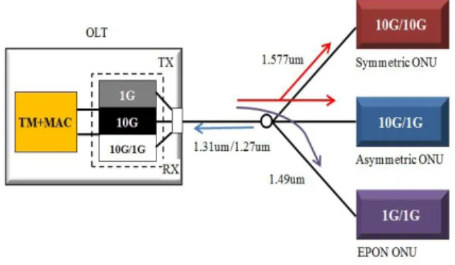
above the data link layer. Figure 1 represents how 10GEPON coexists with EPON. The 10G EPON hierarchical model is suitable with the coexistence of 1G and10G. Since, for avoiding many changes in the MAC layer, the physical layer is re-defined a little. The Physical Media Dependent (PMD) sub-layer and the Physical Medium Attachment (PMA) sub-layer are quite different. The Forward Error Correction (FEC) function in EPON is elective but in 10G EPON protocol, FEC is a essential characteristic. For interface, 10G EPON needs changing the Gigabit Medium Independent Interface (GMII) into XGMII (around 10Gbps). The10G EPON protocol hierarchy is redefined by IEEE802.3av working group [17].
Figure 1: 10g EPON tree topology
The novel hierarchical model is comfortable with 1G EPON and it can be reliably configured to symmetric rate model, 10G/10G and 10G/1G asymmetric rate model. There are three kinds of ONU, involving: 1G/1G ONU, 10G/1G ONU and 10G/10G ONU. As the rate of downlink and uplink has highly changed from 1Gbits/s to 10Gbits/s, the10G EPON operating frequency has also changed. The MAC layer, Physical Code Sub layer (PCS) sub-layer and Reconciliation Sub layer (RS) sub-layer described in the protocol have modified correspondingly. The MAC sub-layer explores the Multi-Point Control Protocol (MPCP) layer depending on the MPCP explained by the prior IEEE802.3ah. Two bytes have been appended to the Discovery Gate frame forwarded by the OLT side to determine whether the OLT had the capability to support uplink 1G and 10G and determine if the current Discovery Window was 1G or 10G. Two bytes have also been appended into the corresponding registration request frame forwarded by every ONU to determine whether the ONU has the capability to support uplink 1G and 10G and to determine if the current registration request forwarded by the ONU was for uplink 1G or 10G. In this manner, 10G EPON and EPON are comfortable with each other. This compatibility can offer upgrade of the available EPON devices.
Figure 2: The Grant frame
Figure 3: Request frame 2.5 EPON System Structure
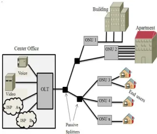
Ethernet passive optical network (EPON) is a kind of single-fiber bidirectional access network that follows point to multiple points (P2MP) structure and the typical structure is the tree structure as depicted by the Figure 4. EPON system is consisted of optical network unit (ONU) at the users-side, optical line terminal (OLT) at the local side and optical distribution network (ODN). EPON follows the wavelength-division multiplexing (WDM) of two wavelengths (upstream 1310nm/ downstream 1490nm), and enforces duplex communication and allows CATV [29] side-channel, to which 1550nm wavelength can be overlaid. Downstream and upstream bandwidths are 10Gbit/s or 1Gbit/s. In downstream direction (from the OLT to ONUs), the
signals forwarded by the OLT can arrive every ONU via POS or ODN. In upstream direction (from ONUs to the OLT), the signals forwarded by ONU will not arrive other ONUs but the OLT. To neglect data conflict and enhance bandwidth usage, EPON also follows TDMA mechanism and arbitrate every requested transmission window of ONUs in upstream direction. ODN offers optical channel between ONU and OLT.
The OLT in the network side, placed in the central office, is utilized for linking the optical access network (OAN) to wide area network (WAN) or metropolitan area network (MAN). The OLT will offer several Ethernet interfaces with 10Gbit/s and 1Gbit/s [17] for supporting WDM transmission. The OLT also helps connection of SDH/SONET [30] [31] interface with speeds i.e.: ATM and OC3/12/45/192. Offered that it is needed to support conventional TDM voice, general telephone line (POTS) and other kinds of services, M interaction (T1/E1) can be multiplexed and linked to PSTN interface. It can be a L3 router or L2 switch, offer network concentration and access, end optical/electricity transformation, bandwidth assignment and control of link of every communication channel and have services of real-time monitoring, management and maintenance [32]. As placed in users-side normally, i.e. FTTB, FTTC and FTTH and primarily utilized to access subscriber terminal, the ONU follows Ethernet protocol to cover the function of switching the second layer and third layer of Ethernet. This kind of ONU can offer high sharing bandwidth for several final subscribers. During mechanism of communication, ONU can transmit data to the subscriber transparently while it is not essential to convert protocol. ONU also supports other conventional TDM protocol without increasing design and operation complexity. It can offer a huge no. of Ethernet interfaces and several T1 interfaces in ONUs with great bandwidth. As for access mode, ONU can be combined into the simple equipment without requiring switching function but utilizing very low cost to assign needed bandwidth for terminal subscriber.
Optical distribution network (ODN) is a point to multiple point tree structure, which can offer transmission platform between the ONUs and OLT. It’s important services are: finishing transmission and dissemination between the ONUs and OLT, demonstrating end -to- end information transmission passage between OLT and ONUs. Several ONUs can be combined to explore transmission distance via optical fiber amplifier (OFA), namely increasing the no. of end subscribers. ODN normally follows passive optical splitter (POS), which is a passive
device linking OLT and ONUs and employed to centralize upstream data and distribute downstream data. The splitting ratio of ODN is between 1:16 and 1:128, namely one OLT can bear 16-128 ONUs. But provided current technological level and economic factors, OLT normally can bear 32-64 ONUs.
Figure 4:EPON System Structure 2.6 EPON Downstream Data Transmission Time division multiplex (TDM) is employed from the OLT to several ONUs to forward downstream data transmission. In accordance of IEEE802.3ah protocol, the mentioned logical link identifier (LLID) [34] of ONUs assigned at the registration time should be contained at the frame header of every data frame. This identifier shows the data frame pertains to specific ONUs (ONU1、ONU2、ONU3…ONUn).
Figure 5: the downstream transmission of EPON In addition, partial data frame can be forwarded to all ONU (broadcast type) or a particular group of ONU (multicast). Under the networking structure of the Figure 2.6, the flow is classified into three groups of signals with every transferred to the interconnected
ONU. As the data signal arrive ONU, the ONU will perform address resolution at the MAC layer with respect to the LLID, obtain the data frame provided to it and abandon the data frames related to other ONUs. For example, in Figure. 5, ONU2 obtains packet 2, 1, 3 and 1; but it only forwards packet 2 to the end subscriber and abandons other data frames [35].
2.7 EPON Upstream Data Transmission
As for upstream, time division multiple (TDM) is employed to assign different time slots for various ONUs to jointly share upstream bandwidth. The OLT will assign bandwidth to every ONU according to the system configuration upon successful ONUs registration. As for PON layer, the bandwidth shows that how much basic time slots that can transfer data, and the unit time length of every basic time slot is 16ns. Under one OLT port (PON port), clocks among PON ports of ONU and the OLT is strictly synchronous. Every ONU only can initially utilize the time slot assigned to transmit data at the authorization time assigned to it by the OLT. Every upstream packet at ONU will not interrupt with each other as the data signals of ONU are certainly coupled to an optical fiber through time slot assignment and delay compensation. For upstream transmission principle, see the Figure 6.
Figure 6: EPON Upstream Data Transmission 2.8 EPON Frame Structure
The primary difference of EPON/10gEPON from other PON systems is that it depends on Ethernet technique, obtains hereditary factors with the core of Ethernet, stores the most significant part of Ethernet and adds multi-address access and remote transmission element and gets breakthrough in distance of transmission and access configuration. In terms of developed standard, and targeting at the new medium 802.3x of PON, IEEE explains new physical layer, but perform least modification of Ethernet
MAC layer so that MAC layer of EPON can be the future suitable protocol for supporting new medium and application. EPON frame format is generally comfortable with Ethernet data frame format of IEEE802.3, and only add information i.e. LLID and time stamp into Ethernet frames.
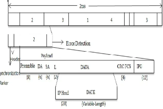
The downstream frame structure [37] of EPON is as indicated by the Figure 7. The downstream data stream is disseminated into the frame with static length and every frame consist different data packets with different length. The time information available at the start of every frame in the synchronous marker form and transfers the synchronous marker, so that ONUs is synchronized with the OLT at particular interval (concerned to the frame length of upstream transmission, it is 2ms shown in the fig). Every data packet with variable length is provided an address of an ONU, shown by the serial nos of ONU i.e.: 1, 2, 3 and N. The data packet is consisted of the payload with header, variable length and error detection area.
The upstream frame structure [8] of EPON is indicated by the Figure 8. The data stream of upstream transmission is classified into frame with static length, every frame is categorized into the time slot allocated to every ONU and every time slot can contain many data packets with increased length. The frame indication is contained at the start of every frame
Figure 7: Downstream frame structure of EPON Every frame of upstream transmission involves time slot of every ONU, which is respectively shown by the serial no.s of 1, 2, 3 and N of ONU. Data packets with time slot overhead and variable length are enclosed in every time slot while time slot overhead primarily involves time indication, guard bandwidth and signal power indication.
Figure 8 Upstream frame structure of EPON III. NETWORK ARCHITECTURE OF
AN MMH
The MMH architecture is a new network PON concept. In the MMH, different service suppliers will be consisted in a single network having various OLTs and every ONU will be used by a SPG. The no. of OLTs is based on the practical scenario for example the no.s of SPGs, in an MMH. If an MMH consists m various service suppliers and the no. of SPGs is n, then the no. of OLTs will be n, for example, OLT1 for the FTTH terminals and OLTn and HDTV/VoD for the FNs and WSNs. Here, the FTTH and HDTV/VoD are taken in the SPG1 and FNs and WSN are taken in the SPGn. On the other side, every ONU will be used by the m/n service suppliers with the m/n different uplink wavelengths. Hence, the no. of OLTs and uplink wavelengths may change; still, for ease, only two OLTs for two SPGs and two uplink wavelengths for four service suppliers. For linking every sensor node to an ONU a cluster-based WSN is assumed where every cluster contains a static cluster head (CH) linked to an ONU by using an optical fiber [6, 7]. In the condition of the FNs, every Femto access point (FAP) will be linked to an ONU by an optical fiber. In the MMH upstream direction, the data packets of a specific service supplier will be consented by the showed OLT by a passive splitter and an array waveguide grating (AWG).
IV. DBAH SCHEME
An upstream frame format for the introduced DBAH mechanism with m service suppliers, and m/n SPGs of the MMH. Still, here, we assume a hybrid PON-based access network with N ONUs (such as N =
NG1 + NG2, where NG1 shows the no of ONUs
linked to the FTTH terminals and HDTV/VoD and
NG2 shows the no of ONUs linked to the CHs of FNs
and WSN), 4 service suppliers, and 2 SPGs. In each DBA algorithm, the distribution of transmission windows to the ONUs is based on the maximum window size wmax and requested window size WR.
In the LS mechanism, the highest distributed window size wmax is based on the cycle time such as length of a polling cycle, Tcycle, as depicted in the following equation:
where, TE shows the Ethernet overhead length, TR represents the Report message length, and TG shows the guard time.
In each DBA mechanism, the Tcycle is a changing parameter that changes from a lowest value to an upper bound, based on the no of active ONUs and their traffic burden. In the MMH, various service suppliers are linked in a single network. Many service suppliers create smaller packet lengths while other facility suppliers create larger packet lengths. Therefore, Tcycle will be more variable and that will create higher jitter. In the introduced DBAH mechanism, two different maximum transmission windows such as max G1 W for SPG1 and max G2 W for SPG2, are employed to solve the jitter problem and to enhance the bandwidth using efficiency. With respect to DBAH mechanism the Tcycle in (1) can be computed as explained:
Since max 1 max G2 G W W , we evaluate the existing bandwidth savings WS employing the equation below:
In summation to this bandwidth savings we also evaluate the extra bandwidth by categorizing the total ONUs into two groups in MMH network: lightly loaded ONUs and highly loaded ONUs. Equation (4) is utilized to compute the total extra bandwidth of the introduced hybrid PON.
where, Wexcess shows the extra bandwidth at a time cycle, LG1 and LG2 represents the no of lightly loaded ONUs in SPG1 and SPG2, respectively, and R
m x W / shows the requested window size of lightly
loaded ONUm/x at a time. The described equation is utilized to properly allocate the total extra bandwidth evaluated in (3) and (4) among the heavily loaded ONUs to remove the congestion problem of the MMH networks:
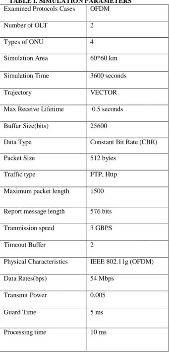
V. PERFORMANCE EVALUATION AND SIMULATION RESULTS In this section, the introduced DBAH scheme performances for the MMH network are analyzed in terms of the mean end-to-end packet delay, throughput and jitter. The computation was done by laboratory made computer simulation programs. We considered that the hybrid PON architecture had 32 ONUs and two OLTs. Moreover, we considered that the transmission speed was 1Gbps for both the downstream and upstream channels. The distances from the ONUs to the OLT were considered to be random and in the coverage area 80-100 km for the long range (LR) hybrid PON and 10–20 km for short range (SR) hybrid PON. A highly violently self-similar network traffic model was utilized to produce the data packets for all the service supplier. The burst traffic from 0 to multiple packets was produced by this self-similar traffic model. The service scheme was considered to be on a first-in first-out basis with an infinite buffer size for every ONU. The parameters of simulation are explained in Table 1. The results of simulation are utilized for the comparison of system performances of the introduced DBAH mechanism with those of the available LS mechanism. Fig. 9 shows the comparison of mean packet delay with the provided load between the DBAH and LS mechanisms for 2-ms cycle time. The comparisons are presented for both the LR and SR PONs. From the comparison of both the situations, we can show that the DBAH mechanism performs better as compared to the LS scheme. The end-to-end packet delays for the introduced DBAH mechanism are far as compared to the LS mechanism. The performance of jitter of the available LS scheme and the introduced DBAH scheme for 2-ms cycle time are depicted in Fig. 10. The DBAH mechanism offers importantly lesser jitter as compared to the LS mechanism for both the LR and SR PONs. These results ensure that the presented algorithm offers lesser fluctuation in data packet arrival times between the two successive time cycles. Fig. 11 compares the throughput between the DBAH and LS schemes for a range of provided load of 0-1.0. From the comparison it is noted that the introduced DBAH mechanism offers almost 80% higher throughput as compared to the LS mechanism at the highest provided load of 1.0. All these performance enhancements are achieved because of usage of extra bandwidth from the lightly loaded ONUs to the heavily loaded ONUs, usage of two different maximum transmission windows for two SPGs, usage of different uplink wavelengths for different service suppliers in a SPG.
TABLE I. SIMULATION PARAMETERS Examined Protocols Cases OFDM Number of OLT 2 Types of ONU 4 Simulation Area 60*60 km Simulation Time 3600 seconds Trajectory VECTOR Max Receive Lifetime 0.5 seconds Buffer Size(bits) 25600 Data Type Constant Bit Rate (CBR) Packet Size 512 bytes
Traffic type FTP, Http Maximum packet length 1500
Report message length 576 bits Tranmission speed 3 GBPS Timeout Buffer 2
Physical Characteristics IEEE 802.11g (OFDM) Data Rates(bps) 54 Mbps
Transmit Power 0.005 Guard Time 5 ms Processing time 10 ms
Fig. 9 Comparison of packet delay for 2-ms cycle time
Fig. 10 Comparison of jitter for 2-ms cycle time
Fig. 11 Comparison of throughput in upstream direction for 2-ms cycle time
0 1 2 3 4 5 6 10 min. 20 min. 30 min. 40 min. 50 min. SR LS LR LS LR DBAH SR DBAH 0 1 2 3 4 5 10 min. 20 min. 30 min. 40 min. 50 min. LR LS LR DBAH 0 1 2 3 4 5 10 min. 20 min. 30 min. 40 min. 50 min. LR LS LR DBAH
CONCLUSIONS
In this research paper, we have introduced a new DBA algorithm for the OLT and multi-wavelength PON-based hybrid networks. The MMH network architecture with the introduced DBA algorithm performed better in comparison of the available LS mechanism in terms of jitter, end-to-end packet delay and throughput. The introduced mechanism offers more than 400% less jitter and 50% less delay with 80% higher throughput as compared to the LS mechanism at a provided load of 1.0 and 2-ms cycle time. The introduced scheme performance will be more important if the simulation is iterated for larger number of SPGs, OLTs and upstream wavelengths.
REFERENCES
[1] J. Zheng and H. T. Mouftah, “A survey of dynamic bandwidth allocation algorithms for Ethernet Passive Optical Networks,” Opt. Switching Networking, vol. 6, pp. 151-162, July 2009.
[2] G. Kramer, B. Mukherjee, and G. Pesavento, “Interleaved polling with adaptive cycle time (IPACT): a dynamic bandwidth distribution scheme in an optical access network,” Photonic Network Commun., vol. 4, pp. 89–107, Jan. 2002.
[3] EPON spec IEEE 802.3ah Task Force, [Online]. Available: http://www.ieee802.org/3/efm.
[4] W. Willinger, M. S. Taqqu, R. Sherman, and D. V. Wilson, “Self-similarity through high-variability: Statistical analysis of Ethernet lan traffic at the source level,” IEEE/ACM Trans. Netw., vol. 5, pp. 71–86, 1997. [5] S. R. Sherif, A. Hadjiantonis, G. Ellinas, C. Assi, and M. A. Ali, “A novel decentralized Ethernet-based PON access architecture for provisioning differentiated QoS,” J. Lightwave Technol., vol. 22, no. 11, pp. 2483-2497, Nov. 2004.
[6] N. Kim, H. Yun, J. Yoo, T. Kim, B.-W. Kim, and M. Kang, “Performance enhancement of differentiated services in E-PON: Smaller buffer and efficient traffic service isolation,” in Proc. OFC, Anaheim, CA, pp. 208–210, Mar. 6–11 2005.
[7] G. kramer, B. Mukherjee, and G. Pesavento, “IPACT: a dynamic protocol for an Ethernet PON (EPON),” IEEE Commun. Mag., vol. 40, pp.74-80, Feb. 2002.
[8] Y. Luo and N. Ansari, “Limited sharing with traffic prediction for dynamic bandwidth allocation and QoS provisioning over Ethernet passive optical networks,” J. Opt. Netw., vol. 4, no. 9, pp. 561–572, Sep. 2005.
[9] J. Zheng and H. T. Mouftah, “Adaptive scheduling algorithms for Ethernet passive optical networks,” in IEEE Proc. Commun., vol.152, no. 5, pp. 643–647, Oct. 2005. [10] Banerjee, G. Kramer, B. Mukherjee, "Fair sharing using dual service-level agreements to achieve open access in a passive optical network," Selected Areas in Communications, IEEE Journal on , vol.24, no.8, pp.32-44, Aug. 2006.
[11] I.S. Hwang, Z.D. Shyu, L.Y. Ke and C.C. Chang, “A Novel Early DBA Mechanism with Prediction-based Fair
Excessive Bandwidth Allocation Scheme in EPON”, Computer Communications, vol. 31,Issue 9, pp. 1814– 1823, June 2008.
[12] P.W. Shumate, “Fiber-to-the-Home: 1977-2007,” IEEE/OSA J. Lightwave Tech., Vol. 26, No. 9, pp. 1093-1103, May 2008.
[13] S.-J. Park, C.-H. Lee, K.-T. Jeong, H.-J. Park, J.-G. Ahn, and K.-H. Song, “Fiber-to-the-home services based on wavelength-division-multiplexing passive optical network,” J. Lightw. Technol., vol. 22, no. 11, pp. 2582– 2592, Nov. 2004.
[14] “Broadband Optical Access Systems Based on Passive Optical Networks (PON),” ITU-T recommendation G.983.1.
[15] GPON spec ITU G.984.x Series of Recommendations; http://www.itu.int/T-REC-G/4
[16] S.J. Trowbridge, “High-speed Ethernet transport,” IEEE Commun.Mag., vol. 45, no. 12, pp. 120–125, Dec. 2007.
[17] IEEE P802.3av Task force, [Online]. Available: http://www.ieee802.org/3/av/
[18] M. Abrams, P.C. Becker, Y. Fujimoto, V. O'Byrne, D. Piehler, "FTTP deployments in the United States and Japan-equipment choices and service provider imperatives," Lightwave Technology, Journal of , vol.23, no.1, pp. 236- 246, Jan. 2005.
[19] H. Mukai, T. Yokotani, T. Kida, "Rapid Growth of FTTH by Use of PON in Japan," IEEE Globecom Workshops, pp.1-3, 26-30 Nov. 2007
[20] K. Rookstool, "Economic considerations of central office (CO) broadband distribution terminals vs. remote terminal (RT) broadband distribution terminals for deploying fiber to the home (FTTH)," Optical Fiber Communications Conference, vol. 2, pp. 610- 611, 23-28 Mar. 2003
[21] G.van den Hoven, "FTTH deployment taking off in Europe," 5th International Conference on Broadband Communications, Networks and Systems, pp.221, 8-11 Sept. 2008
[22] W. Li, Z. Zhang; L. Xie, "A Proposal for Bandwidth Consumption in FTTH Networks in China," IEEE Photonics Global Singapore, pp.1-4, 8-11 Dec. 200 [23] Huang, L.Shan, W. Li, A. Xu, L. Xie, "Solutions to Challenges of FTTH Deployment in China," IEEE Globecom Workshops, pp.1-3, 26-30 Nov. 2007.
[24] M. Hajduczenia, H.J.A. da Silva and P.P. Monteiro, “On efficiency of Ethernet Passive Optical Networks (EPONs),” IEEE Symposium on Computers and Communications, pp. 566-571, Jun. 2006
[25] T. Orphanoudakis, H.-C. Leligou, E. Kosmatos and J.D. Angelopoulos, “Performance evaluation of GPON vs EPON for multi-service access,” International Journal of Communication Systems, vol. 22, no. 2, pp. 187-202, Oct. 2008