Abstract— This work presents the analysis of the performance of PI speed controller for the sensorless speed control of Permanent Magnet Synchronous Motor (PMSM) using Model Reference Adaptive System (MRAS). The aim of the study to prevent speed overshot in start-up time of the motor and provides a better dynamic response in transient states. In addition, this study, in order to eliminate distortions caused by sensors that MRAS sensorless control method, due to its simplicity and good stability has been preferred for the estimation of speed. The application of a PI Controller for the speed control of field oriented PMSM fed by voltage source inverter under load variations is considered. Extensive simulation results are presented using MATLAB/SIMULINK program which including (SVPWM generation, inverter, PMSM, the reference frame transformation and different PI controllers) as well as the estimation method using MRAS.
Index Terms— MRAS; PMSM; SVPWM; PI Controller.
I. INTRODUCTION
Industrial progress is necessity of today from the point of view of looking after and betterment, it billions people of the world. Alternating current machine are helping very much in attaining the goal of development. We are using AC machine of different types for different purposes at some place we require conveyor belts, robot operations, cranes for shifting load beyond imagination as well as there are a number of industrial works like paper mills, waste water treatment work .Everywhere AC machines are providing help.
Among different types of ac drives, permanent magnet synchronous machine (PMSM) has become very important now a days .it is gaining because of its specific features like high power density, improve efficiency, high value of torque inertia ratio and high reliability.
Now a days an other reason has also appeared for the importance of PMSM from the point of view of competitive market. The cost of magnetic materials materials with high energy density and coactivity (e.g., samarium cobalt and neodymium-boron iron) is reducing so PMSM is providing better gain PMSM manufacturer and suppliers.
In the high performance applications, the PMSM drives are ready to meet sophisticated requirements such as fast dynamic response, high power factor and wide operating speed range. This has opened up new possibilities for large-scale application of PMSM. Speed control of traditional PMSM drive system is obtained by taking rotor position or speed information from shaft sensor such as an optical encoder or resolver. The use of these types of sensors increases system
complexity, weight and the cost. Speed position sensorless systems overcome the shortcomings of the above, and improve system reliability, robustness and the dynamic performance.
A variety of techniques have been developed to eliminate the rotor position sensor in PMSM applications. In general sensorless control techniques of PMSM, Lunberger or Kalman filter observers, sliding mode control, MRAS estimators, high-frequency signal injection method, fuzzy logic and artificial intelligence, is on direct control of torque and flux .
In this paper focus is on designing the MRAS algorithm in order to estimate rotor speed. Its purpose is to decrease the time to reach a speed reference of the PMSM system when the load torque changes suddenly.
Model reference adaptive speed control (MRASC) for vector controlled PMSM drive consists of two functional blocks. The first one is direct FLC whose inputs are the error and change of error measured between the actual, motor speed and the desired speed, and its output is the command current (torque command). The second one demonstrates the model reference controller is adaptive scheme. In the proposed system, the output speed of equipment reference model is compared to the actual speed of the motor. This paper also introduces a PI control for speed control of a PMSM drive. The aim of this study, is to obtain a controller that eliminates the over speed in startup and provides a fast and smooth dynamic response for the speed control of PMSM.
II. SENSORLESS CONTROL METHODS OF PMSM The term sensorless control means elimination of the rotor position sensor or speed sensor, i.e. sensors for mechanical quantities located on the machine shaft. Sensorless methods use many different principles. These methods usually processed stator voltages and currents. The common sensorless methods are working with the mathematical model of machines or injection methods. The mathematical model of a machine describes the behavior of the machine in dependence on the supply voltage and on the load torque. For simplicity the mathematical model ignores many actual properties of electric machines. This affects the accuracy of the mathematical description and limits its use. There are many mathematical models on which a lot of more specific methods are based, such as MRAS, various types of observers, integration methods, Kalman filter etc.
From the view of state values the counter-voltage and magnetic flux can primarily be used for the estimation. The counter-voltage can be estimated by using an observer; the
Analysis of Sensorless Permanent Synchronous
Motor Using PI and Adaptive Control Scheme
Neelanshu, Pratibha Tiwari
integration approach is typical for magnetic fluxes. Usually the stator current and voltage vectors are used as the input data for the estimation. If the neutral wire is not led out of the machine, it is possible to measure the currents of two phases and calculate the third one. The easiest way to get the stator voltage is to obtain it from the current switching combination and the measuring of the voltage of the link circuit.
III. MODELLING OF PMSM
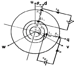
A permanent magnet synchronous motor is a revolving-field type where the field magnet rotates to assume the brushless with a synchronous motor which uses a permanent magnet for the field magnet. Figure 2.1 shows the structure of cylindrical shape.
Fig.1: Structure of surface permanent magnet synchronous motor
3.1 Representation of three-phase AC circuit equation
Figure 2 is the equivalent circuit of 3 phase cylindrical permanent magnet synchronous motor. The circuit equation of the relation of voltage, current and impedance from the equivalent circuit becomes.
Here, vua , vva , vwa are the armature voltage of u,v,w phase.
i
ua, i
va, i
wa are the armature current of u,v,w phase.e
ua, e
va,
e
wa are a speed electromotive force which is induced in theu,v,w phase armature winding by permanent magnet magnetic
field. Ra is the armature winding resistance. La is self-inductance of the armature winding. Ma is a mutual inductance between armature winding. P(= d dt) is a differential operator. When the maximum value is assumed to be φfua ,φfva ,φfwa field magnets of u,v,w phase armature winding interlinkage fluxes to generate eua , eva , ewa becomes.
Fig.2: The equivalent circuit of three-phase cylindrical permanent magnet synchronous motor
fua=
facos θ
re
fva=
facos (θ
re- 2 / 3) (1)
fwa=
facos (θ
re+ 2 / 3)
Here, θre is an angle of the field magnet taken clockwise based on u phase of armature winding (electrical angle), and ωre the angular velocity of the magnetic field (electrical angle) are express as follow:
θ
re=
redt (2)
In this case, eua , eva , ewa becomes:e
ua= P
fua= -ω
re
fasin θ
ree
va= P
fva= -ω
re
fasin (θ
re- 2 / 3) (3)
e
wa= P
fwa= -ω
re
fasin (θ
re+ 2 / 3)
In the armature winding, there is also a leakage inductance la
and its relation with the self-inductance of the armature winding is express in the next equation.
L′aaa = l +M′ (4)
Furthermore, the number of pole pairs is assumed to be p , the rotation speed ωrm of the output shaft of a synchronous motor (mechanical angle) is ωre / p .
3.2 Coordinate transformation
As for the grasp of the control system characteristic deriving the control method, it is easier when it is represented by 2 phase than to be represented by 3 phase alternative current and voltage. Moreover, it is simple to represent 2 axis direct current than 2 phase alternative current. To change the view of the motor this way, it is necessary to change the coordinate view, this is called coordinate transformation.
3.3 Two phase circuit equation
I. (α − β) circuit equation coordinate system
The circuit equation of (α − β) from 3 phase alternative current through the coordinate transformation is showed equation (2.6).
Figure 3 shows the equivalent circuit.
Fig.3: The equivalent circuit 2 phase alternative current
Here, vαa , vβa are axis armature voltage, iαa , iβa are phase armature current, eαa , eβa , are the speed electromotive force induced by phase armature windings of the field permanent magnet. Ra is armature winding resistance, La is
self-inductance of the armature winding, a R is the same as equation (1), La is represented in next equation using laa ,M′a of equation (1).
II. d-q circuit equation coordinate system
The motor has the fixed and rotating part. Converting them into the orthogonal coordinate system where orthogonal coordinate system d-q transformation rotates them both fixed, that system of coordinates is d-q coordinate system. q-axis has π / 2 phase advanced compare to d-axis. The circuit equation of dq from (α − β) circuit equation coordinate system is:
(6) The second term of right side of this equation generated speed electromotive force
e
da, e
qa in d-q axis of armature winding by the permanent magnet magnetic fieldare e
da= 0 , e
qa=ω
reφ
fa .Fig.4: Equivalent circuit of d-q coordinates
If vda, vqa are assumed to be a direct voltage, ida, iqa becomes direct current too and it is possible to treat in two axis direct current. Furthermore, because the field magnet is in d-axis, it is generated only in an advanced on q-axis of π/2 , and the right term of equation (6) is a direct voltage in d-q axis armature winding according to the field magnetic of permanent magnet as described earlier and generates speed electromotive force.
3.3 Torque
Te is the motor torque generated by the Fleming's left hand law. However, the revolving-field type motor torque is the torque applied to the field (Fleming's left hand law in the positive direction of torque has been applied to the armature windings). It is represented by the sum of product of orthogonal armature current and armature winding flux. Torque equation is:
T
e= p
fa{ - i
uasin θ
re– i
vasin (θ
re- 2 / 3)-
i
wasin (θ
re+ 2 / 3)} (7)
T
e= p
fa{ - iα
asin θ
re+ iβ
acos θ
re} (8)
= p
fai
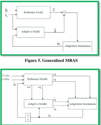
qaIV. MODEL REFERNCE ADAPTIVE SCHEME FOR PMSM In the MRAS method, the motor speed is estimated using a reference model and adaptive model. The reference model, which is independent of the rotor speed, calculates the state variable ψrs from the terminal voltage and current. Then the adaptive model, which is dependent on the rotor speed, estimates the state variable ψr
r
. The difference between these state variables is then used to drive an adaptation mechanism which generates the estimated speed ω̂r. The generalized structure of MRAS is shown in Figure 5. The reference model and adaptive model have the same input. x and x ̂ are respectively the state variable of the reference model and adaptive model. Given performance index x is set by the reference model, which is compared with the corresponding performance of adaptive model x ̂. The difference value is the input of adaptation mechanism . The variable in adaptive
model is modified by adaptation mechanism, in order to make its state variable x ̂ draw near x which also means the
difference value approaches zero.
Figure 5. Generalized MRAS
Figure 6. Structure of MRAS
This strategy selects PMSM itself as the reference model and its current model as the adaptation mechanism. MRAS sensorless control is mainly based on the model of the motor at the rotating reference plane. Stator voltage equations on rotating dq reference plane and flux equations are defined as follows.
u
d= R i
d+ L
d– ω
rL
qi
q(1)
u
d= R i
q+ L
q– ω
rL
di
d+ ω
rψ
r(2)
Where ud, uq are stator voltage component in d − q frame of axes; id, iq are stator current component; Ld, Lq are stator inductance; R is stator resistance; ψr is rotor flux; ωr is rotor speed.=
i
d+
i
q+
u
d(3)
=
i
q-
i
d+
u
q-
(4)
According to ultra-stability theory, the following conditions must be met in order to maintain the feedback system stable. (1) Transition matrix H(s) = (sI − A)-1 must be strictly positive real.(2) Popov integral inequality is (0,t1) = T w dt - 20 in which,∀t1 ≥ 0, 2
0 is a finite positive constant independent of t1. So far, the MRAS is asymptotic stable.
The adaptive law is shown in 5, which is obtained by inverse solution to Popov integral inequality.
r = ( Kp + Ki/s) is is = ( Kp + Ki/s) (id iq – iqid).iq (5) Equation (6) is obtained by substituting equation (4) into equation (5).
r = ( Kp + Ki/s) (id iq – iqid – ψr/L (iq - iq )) (6)
Where id, iq are obtained from the adjusted model, and id, iq are obtained from the referenced model.
Adaptation mechanism consists of a PI controller as shown in the equation (6). PI controllers are widely used in industrial control systems applications. They have a simple structure and operation over a wide range can offer satisfactory performance. Therefore, a simple static gain linear PI controller is used the estimated rotor speed to produce the majority of adaptation designs in the literature for the MRAS speed observers.
V. SIMULATION &RESULT
The simulation environment of Simulink has a high flexibility and expandability which allows the possibility of development of a set of functions for a detailed analysis of the electrical drive. Its graphical interface allows selection of functional blocks, their placement on a worksheet, selection of their functional parameters interactively, and description of signal flow by connecting their data lines using a mouse device.
The PMSM drive simulation was built in several steps like dqo variables transformation to abc phase, calculation torque and speed, control circuit and PMSM. The dqo variables transformation to abc phase is built using the reverse Parks transformation. For simulation purpose the voltages are the inputs and the current are output.
The system built in Simulink for a PMSM drive system has been tested with the space vector modulation method at the constant torque region of operation.
The motor parameters used for simulation are given in Table1
Variables
Value
Stator phase resistance
1.6
d-axis Inductance
0.006365
q-axis Inductance
0.006365
Flux linkage establish by
magnet
0.1852
Voltage Constant
67.1831
Torque Constant
0.5556
Inertia
0.0001854
Friction Factor
5.396e
-005Pole pair
2
Initial Condition
0
Rated Speed
4250 rpm
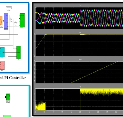
Figure.7: Model of PMSM with MRAS and PI Controller
Figure 8: Model of Space Vector Pulse Width Modulation
Figure 9 shows the real three phase currents drawn by the motor as a result of the SVPWM control for a speed step of 4250 rpm and load of 2.8 Nm. It is clear that the current is non -sinusoidal at the starting and becomes sinusoidal when the motor reaches the controller command speed at steady state.
Figure 9: Waveform of Current , Speed , Angle and Electromagnetic Torque of PMSM
The given speed is set at 4250 rpm, and the motor is in no load startup. When the speed is stable, an abrupt load of 3.2 Nm applied at 0.07s. Simulation waveforms are shown as follows. Figure 10 shows the actual speed, and Figure 9 shows the estimated speed. The comparison of the estimated and actual angle is shown in Figure 9.
Figure 10: Waveform of Speed of PMSM, Speed by MARS 1 and Speed by MARS 2
Figure 11: Waveform of Speed of PMSM
Figure 10 shows MRAS waveforms, it can conclude that MRAS method has a good stable state precision with a steady-state error of less than 1000 rpm.
VI. CONCLUSION
In this paper, it is proposed a sensorless scheme based on MRAS for control of PMSM drive system. The results obtained are compared with a vector control scheme based on indirect FOC method that use the position sensor. Under different operation conditions, simulation results have proved that the proposed sensorless method has a good performance for the torque, speed and position control of PMSM. The MRAS for estimating rotor position angle and speed is based on a stator current estimator, due to the fact that only stator currents are directly measurable in a PMSM drive. The proposed method is simple, needs a low computation capacity and has a high speed adaptation even at very low speeds. This method is more stable and robust because the produced error in the speed adaptation (by PI action) is eliminated. The obtained simulation results, as discussed in above paragraph, are satisfactory in terms of estimation errors, robustness and global stability of the electrical drive system for different operating conditions. Results obtained show that sensorless control strategy based on MRAS approach can be applied successfully in PMSM drives.
VII.
REFERENCES[1] Neha Kataria, Dr. Aziz Ahmad “Simulation of senserless permanent magnet synchronous machine using MRAC” International Journal of Emerging Trends in Engineering Research Volume 2, No.6, June 2014
[2] Missula jagath vallabhai, pankaj swarnkar, D.Mdeshpande “Comparative analysis of PI control and model reference adaptive control based vector control strategy for induction motor drive” (IJERA) Vol. 2, Issue 3, May-Jun 2012
[3] Birou M.T Iulian “Robust control of sensorless AC Drives based on Adaptive Identification”, Recent Advances in Robust Control-Theory and Aplications in Robotics and Electromechanics, Edited by Andreas Mueller ,ISBN 978-953-307-421-4
[4] Kumar P.Sai , J.S.V. Siva Kumar ”Model Reference Adaptive Controlled Application to the Vector Controlled Permanent Magnet Synchronous Motor Drive”-International Journal Of Power System
Operation and Energy Management (IJPSOEM),Volume-1,Issue-1, 2011
[5] Lipeng Wang, Huaguang Zhang, Zhaobing Liu,Limin Hou, Xiuchong Liu,”Research on the Sensorless Control pf SPMSM Based on AaReduced-Order Variable Structure MRAS Observer” ICIC Express Letters ,Volume 4, Number 5, October 2010, ISSN 1881-803X
[6] Piippo A, Luomi J. “Adaptive Observer Combined With HF Signal Injection for Sensorless Control of PMSM Drives,” IEEE International Conference on Electric Machines and Drives,15-18 May 2005.
[7] Raminosoa, T., B. Blunier, D. Fodorean, and A. Miraoui, \Design and comparison of high speed switched and synchronous reluctance machines to drive the compressor of an automotive PEM fuel cell," ICEM Conference, Vol. 57, 2988{2997, 2008.
[8] Kawakami, M. and N. Fujii, \Analytical study of new type of direct drive motor for scroll type of compressor," ICEM Conference, 1{6, 2008.
[9] Fukuda, Y., P. Patisonticharoen, Y. Kikushi, and H. Nakagawara, \Magnet embedded rotor, electric motor using the same rotor, and compressor using the same rotor," U.S. Patent,No. US2010/0166575 A1, 2010.
[10] Zhu, T. Q. and D. Howe, \Electrical machines and drives for electric, hybrid, and fuel cell vehicles," Proceeding of the IEEE, Vol. 95, No. 4, 746{765, 2007.
[11] Matt, D. and J. F. Llibre, \Performance compar¶ees des machines µa aimants et µa r¶eluctance variable. Maximisation du couple massique ou volumique," Journal de Physique III, 1621{1641, 1995.
[12] Magnussen, Song L, Peng J., (2009). The Study of Fuzzy- PI Controller of Permanent Magnet Synchronous Motor. IEEE, IPEC2009, 978-1-4244-3557-9/09/$25.00..
[13] Vas, P., (1999). Artificial-Intelligence-Based Electrical Machines and Drives-Application of Fuzzy, Neural, Fuzzy-Neural and Genetic Algorithm Based Techniques. New York: Oxford Univ. Press.
[14] Zidani, F., M. Nait-Said, M. Benbouzid, D. Diallo, and Abdessemed, R., (2001). A fuzzy rotor resistance updating scheme for an IFOC induction motor drive, IEEE Power Eng. Rev., vol. 21, no. 11, pp. 47–50, Nov.
[15] Karanayil, B., Rahman, M. and Grantham, C., (2005). Stator and rotor resistance observers for induction motor drive using fuzzy logic and artificial neural networks, IEEE Trans. Energy Convers., vol. 20, no. 4, pp. 771–780
BIOGRAPHY
Neelanshu Belong to Singrauli MP. She is pursuing her M.Tech in Electrical Engg. (Control & Instrumentation) from SHIATS, Allahabad, UP-India.
Pratibha Tiwari presently working as Assistant Professor in Electrical Engineering at Sam Higginbottom Institute of Agriculture Technology & Sciences, Allahabad, (U.P) India.
The degree of B.Tech secured in Electrical & Electronics Eng. from UCER, Allahabad in 2002 and M.Tech. in Control and Instrumentation from MNNIT, Allahabad in 2006. Research interest includes Control & Instr. and Power Electronics.