WARNING MESSAGE DISSEMINATION IN VANETS USING SUMO AND
MOVE
K.SIVARAMA KRISHNA (M.Tech), VR SIDDARTHA
ENGINEERING COLLEGE ,VIJAYAWADA
Ms.CH.VIJAYA DURGA (Assistant Professor), VR SIDDARTHA ENGINEERING COLLEGE
ABSTRACT
In Recent survey VANETs have many possible architectures, algorithms and protocols About traffic safety applications and warning message dissemination which are having very less time to reach as well as for highest number of
possible vehicles.so in past we have
manyapproaches to disseminate the warning messages upon multi hop wireless networks with lesstime consumption.our proposed technique used in urban areas where the vehicle density is high and technique for the improvement of message warning dissemination.in this paper for simulation we used one of the routing protocol i.e AODV which allow the usersto generate real world mobility models for VANET simulations the tools required are Ns-2, SUMO and MOVE. MOVE is a tool for open source traffic simulator and the output of MOVE is an real world mobility model. The broadcasting is done in NS-2 we adopt the best technique to eliminate the broadcast storm problem. and to disseminate messages very fastly.
Index terms:broadcast problem, SUMO,MOVE,NS-2,VANET, real profile of city, GPS
I. INTRODUCTION
Vehicular networks are wireless communication networks which do not have any fixed infrastructure and is used for co-operative applications among the vehicles; VANETs shall making driving much safer and more convenient. the U.S. Federal Communications Commission (FCC) allocated a block of wireless spectrum in the 5.850 to 5.925 GHz band for applications primarily intended to enhance the safety and efficiency of highway system
VANETs have many possible applications, ranging from inter-vehicle communication and file sharing, to obtaining real-time traffic information (such as jams and blocked streets), etc. In this work we focus on traffic safety and efficient warning message dissemination and simulation with MOVE. we have many routing protocols for VANETs to disseminate information efficiently in this paper we choose the best routing technique i.e. AODV .the protocol type is reactive the main control messages are RREQ, RREP, RRER. the routing type of AODV is hop by hop the main advantages of this routing protocol is low overhead and it supports of routing techniques like unicast, multicast, broadcast.
In urban vehicular wireless environments, an accident can cause many vehicles to send warning messages, and all vehicles within the transmission range will receive the broadcast transmissions and rebroadcast these messages. Hence, a broadcast storm
(serious redundancy, contention and massive packet collisions due to simultaneous forwarding) will occur and must be reduced [1]. In the past, several schemes have been proposed to reduce the broadcast storm problem. So to reduce the broadcast storm we have to know the specific environment where the vehicles are located. MOVE is the software which is a used for creating maps to simulate either manually or from maps that are presented in TIGER maps
The rest of this paper contains as follows section II reviews the related work on broadcast storm problem section III reviews on AODV routing protocol section IV contains SUMO and section V reviews on MOVE section VI on simulation environment section VII on conclusion and future work of this paper
II. BROADCAST STORM PROBLEM
There are different techniques to reduce the broadcast storm problems
1. Counter based scheme
In this scheme we keep a counter first initialize the counter c=1 when a broadcast message hear for first time if the message heard again then interrupt the message and perform counter to increase 1 now resume the waiting interrupt perform likewise these operations up to C=c where C is the maximum counter value. And cancel the transmission of message if it exceeds the value of C
2. distance based scheme
In this scheme we set a distance for re transmission of messages when a broadcast message hear for first time initialize the distance i.e. dmin and if
dmin<D proceed to rebroadcast otherwise stop the re
broadcasting .where D is the distance to the Host
3. location based scheme
In this scheme we require more precise locations for broadcasting vehicles to achieve an accurate geometrical estimation of additional coverage of warning message dissemination
4. persistence techniques
the persistence techniques like weighted persistence and slotted 1-persistence and slotted p-persistence techniques are probabilistic and timer based broadcast techniques used to reduce the broadcast storm problem these techniques are not used to completely reduce the broadcast storm problem but it is used to mitigate the problem by access the higher priority nodes first quickly as fast as possible this technique and our previous techniques are used for highway scenarios only not for urban scenarios
5. The Last One
In this scheme we find the most distant vehicle from warning message sender , so it is having only allowed the re broadcasting of messages it gives the better performance than previous techniques although it is used to highway scenarios only because it not take obstacles effect into account
6. Stochastic broadcasting technique In this scheme relay nodes rebroadcast the messages according to probability this technique performance is depends upon vehicle density
7. Cross layered broadcast protocol This scheme is mainly based on geographical position and vehicle velocities based on this select a relay vehicle
In this scheme mainly we use 1.Broadcast request to send 2.Broadcast clear to send
Based on these messages we reduce the delay between vehicles and this used only for highway scenarios only.
The above mentioned techniques are only for highway scenarios these techniques gives not better results when tested in urban areas where vehicle density is high
And not effective when obstacles are taken into account, therefore we make use of SBR scheme to overcome the high density of vehicles and obstacles taken into account.
III. AODV
Routing protocol is used for exchanging of information between two entities.It has some procedures to establishing routes, decision forwarding, maintaining of route when one way of route fails.As in VANETs having high density and high mobility the proactive routing protocol is not suitable for VANETs reactive protocol i.e. AODV Which is a dynamic self-starting multi hop routing between participated nodes and establishing all connections and maintain the network.
RREQ, RREP, RERRs are the message types defined by AODV.In AODV when a node receives the packet RREQ it records the information about node sending this query and address of that node in its routing table. this process is called as backward learning, at the destination a reply packet RRER is send through complete path obtained from backward learning procedure, at each stop of the path node records the information regarding previous hop so forward path is established from source. After path is established completely the user uses it as long as ,
when the link failure will be reported to source and will it trigger to another link .
AODV route discovery
To find route it broadcast RREQ to all its neighboring nodes this RREQ contains the address of source and destination their sequence numbers, broadcast ID and a counter, which counts how many times RREQ has been generated from a specific node. When source sent RREQ to neighbors it acquire RREP form either neighbors or the neighbor nodes send this RREQ to their neighbor nodes to increase hop counter. If the node receives number of route requests from same broadcast id then it drop the repeated routes to loop free.
AODV route table management
This is needed because if any routes does not exist in route to eliminate that routes we use destination sequence IDs
AODV route maintenance
When a node in a network is invalid then it discard all the related entries of the node and sent RREP to current active node that route is not valid any more for communication AODV maintains the loop free routes.
IV. SUMO
Simulation In Urban Mobility is an open source Traffic simulator used to simulate the traffic in an area the size of city.
To set up roads network and to simulate the traffic SUMO has some additional tools the simulation is time-discrete and space-continuous the default length of time step is 1second.
ROAD NETWORK
To run the simulation we need a network file and this network file is in a format of XML and it contains the data regarding how the junctions (nodes)
connected with roads(edges).and how the lanes are connected to junctions , also speed of vehicles and number of lanes containing each road and no of vehicles and also the information about traffic light.There are several ways to generate this network file mostly by using ―net convert‖ which is built in command in SUMO another file we use for road simulation is edge type file which is default values taken by SUMO for generation of random network we have a command like ―net generate‖
The most important feature of this SUMO is import a road network file from OSM(open street maps).) OSM is like to accesses by any one and freely contribute the geometric data.so that we can easily import the road network that can be used in traffic simulations. To use OSM maps first we download by
selecting a rectangular area from
www.openstreetmaps.org or by giving the values to the boundary boxes and the alternative for this is sending a HTTP request to OSMAPI. The map selected from openstreet maps as shown in fig 1.
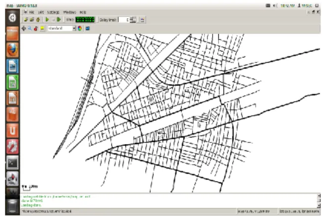
And after conversion of OSM file to network file the fig is shown in 2.
The downloaded OSM file simply contains list of data about nodes, ways, relations. This OSM file given as input for ―netconvert‖ to generate a network file which is used by SUMO.
Fig1: selected area from openstreet maps to simulate
Fig2 :conversion of OSM file to network
GENERATING TRAFFIC
Once the network file is generated it is time to describe the vehicle flows on that network so it is described as route file it also in XML format. This route file mainly contains vehicle types and routes taken by vehicles and themselves.
Vehicle type defines the physical properties of vehicle and behavior of the driver and also include maximum speed acceleration and length of vehicle routes are a list of connected edges along with vehicle can drive. and also vehicle is defined by what route it is taken and what is the time to enter in to simulation flow determines a time period during which a certain number of vehicles (of the same type) are added into the simulation to take the specified route. Vehicles created by flow are distributed equally over the given interval.
So to generate route file from network file we use the command ―activitygen‖. This took a network file and statistic file as input this statistic file contains some general aspects like number of households and number of working people and number of habitants ,positions of schools and play grounds The created route file is not yet usable because the routes are defined only by the first and last edge so another tool ―duarouter‖ must be used to calculate the exact path a vehicle will take
Data extraction andvisualization
when the network file and route files and configuration file is generated in sumo it is time to visualization by using SUMO GUI and also several aspects of output to write edges creation and position of vehicles by defining the xy-position.And also SUMO contains few python scripts to visualize road traffic and some aggregated outputs.
V. MOVE
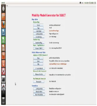
MOVE runs in java and it is atop open source traffic simulator, MOVE contains mainly two components one is map editor and another one is movement editor the map editor is used to create a road topology
The map can create either manually or automatically i.e imported from publically available maps such as TIGER maps. The vehicle movement editor allows the user to create turns ,trips file on roads. the vehicle movement patterns also created manually , generated automatically the information users input in the map editor and movement editor is then fed into a SUMO to generate mobility trace which is immediately used by simulation tool such as NS-2 to simulate realistic vehicle movements users can also visualize using the visualization button from main menu.
MAP EDITOR
in MOVE the road map can create either manually or automatically manually created map requires two main concepts nodes and edges node is defined as a particular junction or dead end to the road further it can be classified as the junction roads are normal road junction or traffic light nodes. The edge is connection between two points on the map. This edge include speed, priority, road length, number of lanes per road
we have also integrated google earth maps into MOVE to facilitate the creation of nodes in a realistic setting.
Simply choose the node from MOVE menu and add some node id’s and starting and ending times
Three maps are currently available as random maps they are grid , spider ,random maps and some of parameters associated with this random maps are number of grids and number of junctions we choose randomly.
Fig3 . MOVE menu to select nodes,edges
MOVEMENT EDITOR
The vehicle movement generated by manually or automatically using vehivle movement editor to generate vehicle movement first we generate flow definition file the parameters of flow contains starting and ending road, the time to start and end the flow in addition MOVE user can define the probability of turning turning to different directions at each junctions.
Simply select the vehicle movement from menu and create some parameters to this id’s
VI. SIMULATION ENVIRONMENT
Here in this simulation we compared AODV and DSR routing protocol and plot the results obtained and we simulate the map from openstreet maps as shown in fig. Creation of road topology using MOVE and vehicle movement generation using MOVE, the broadcasting of messages between vehicles is done using NS-2 so the architecture of this simulation environment is shown in fig.
Fig5. road and vehicle, movement creation
as shown in fig the traffic and road configuration is setup and then simulation is performed
up to now we saw the creation of map and traffic now for broadcasting the messages we used NS-2 tool so the broadcasting of packets is as shown in fig.
Fig6.Broadcasting of messages in NS-2
After broadcasting packets we have to plot the results of AODV that are shown in fig7.
As shown in the fig contains data about AODV under attack and under normal conditions based generation of Trace file by simulating the VANET configuration.
CONCLUSION AND FUTURE WORK
So that the road topology , map creation and network creation and mobility creation is by using MOVE and SUMO and the broadcasting of packets is by using NS-2 as shown in fig6 .
REFERENCES
[1] Y.-C. Tseng, S.-Y. Ni, Y.-S. Chen, and J.-P. Sheu, ―The broadcast storm problem in a mobile ad hoc network,‖ Wireless Netw., vol. 8,
pp. 153–167, 2002.
[2]. N. Wisitpongphan, O. K. Tonguz, J. S. Parikh, P. Mudalige, F. Bai, and V. Sadekar, ―Broadcast storm mitigation techniques in vehicular ad hoc networks,‖ Wireless Commun., vol. 14, pp. 84–94, 2007.
[3]. K. Suriyapaibonwattana and C. Pornavalai, ―An effective safety alert broadcast algorithm forVANET,‖ in Proc. ISCIT, Oct. 2008, pp.
247–250.
[4].OpenStreetMap, ―OpenStreetMap, collaborative project to createa free editable map of the world,‖ 2011 [Online]. Available:
http://www.openstreetmap.org
[5].D. Krajzewicz, G. Hertkorn, C. Rossel, and P. Wagner, ―SUMO (Simulation of Urban MObility)— An open-source traffic simulation,‖ in Proc 4th
MESM, Sharjah, UAE, Sep. 2002, pp. 183–187.
[6]. K. Fall and K. Varadhan, ―ns notes and documents,‖ The VINT Project.UC Berkeley, LBL, USC/ISI, and Xerox PARC, 2000.