Implementation of Adaptive Embedded Controller for
a Temperature Process
J. Satheesh Kumar
1,*, Deepu Sankar
21Department of Electronics and Instrumentation, Dayananda Sagar College of Engineering, Bangalore, India 2
Department of Electronics and Instrumentation, Karunya University, India
Received 08 December 2017; received in revised from 11 April 2018; accepted 18 August 2018
Abstract
The paper proposed and carried out an adaptive embedded control strategy with the help of Arduino open
hardware platform. The proposed control strategy is to carry out a cost-effective interface between the simulation
software and a real-time process. The data acquisition and control is done with the help of Arduino Uno which has
been interfaced with MATLAB Simulink The control algorithms developed in Simulink model can be downloaded
into the Arduino Uno, working as a standalone controller. In this paper, various control algorithms are used to
control the temperature process, including embedded Modified Model Reference Adaptive Control (MMRAC). Its
performance is compared to other control algorithms. The result shows that the MMRAC scheme improves the
transient performance of the temperature control system.
Keywords: embedded, control, MATLAB, Simulink, MRAC
1.
Introduction
Nowadays, the automation and control of most of the real-time systems are achieved by using a computer connected
through the expensive Data Acquisition System (DAS). The specification and requirement of DAS depend on the software
being used. The proposed methodology uses a low-cost DAS and an embedded system to develop a controller that can give
better performance. The development of DAS and the controller in the same hardware improves the compactness of the
proposed system. In this paper, the Arduino Uno micro controller is used for the development of DAS and controller. The
control algorithm is developed using MATLAB Simulink tool. Tawanda [1] presented similar algorithm developments using
Simulink. The MATLAB Simulink provides a platform to interface Simulink with Arduino Uno through Arduino IO library
and support package. The development of the control algorithm in the embedded system has become simpler by this approach.
The early versions of the embedded target devices for Simulink tool are expensive. The Real-Time Interface (RTI) developed
by Arduino Uno, is cost effective.
Five different control algorithms, namely Proportional Control (P), Proportional-Integral Control (PI), Proportional
Integral Derivative Control (PID), Model Reference Adaptive Control (MRAC) and MMRAC were developed to control a
temperature process using Simulink. There are two ways to test the developed algorithm in real-time. One method is to use the
Arduino Union, along with the MATLAB Simulink running on the PC. Another way is to use Arduino Uno as a standalone
controller in real time. In the second case, after downloading the control algorithms in Arduino UNO microcontroller, the
computer can be disconnected from it. The second method provides the flexibility of using the Arduino Uno as a standalone
embedded controller. This embedded controller is used to control the temperature process in real-time environment.
* Corresponding author. E-mail address: [email protected]
The PID controller is used in process industries to control various processes. Based on the necessity and nature of the
process, the adaptive controller is considered as a suitable controller for many processes. MRAC is one such adaptive
controller. Several adaptive control structures are discussed by [2] and [3]. The robustness of the control system are improved
by combining both PID and adaptive control action. The result presented by [4] shows the improved performance by the
addition of PID in adaptive control.
A modified control scheme of MRAC is discussed in this paper. In the Modified MRAC, PID controller action is included.
The error given to the PID controller is derived from the model output and the process output. The combined action of the PID
controller and MRAC drives the final control element in the process. This adaptive controller will give better settling time and
efficiency compared to MRAC. Therefore an Arduino aided MMRAC is another main aspect of the paper. The most significant
property of a real-time interface in MATLAB Simulink and Arduino UNO helps in the development of standalone controller.
Hence this work is identified as an Adaptive Embedded controller for a temperature process.
2.
Simulink-Arduino Real Time Interface
MATLAB and Simulink have been associated with engineering and academic world as a design and development tool.
The method of linking, design, and development into the real-time process in an optimized way is a challenging task. Standard
data acquisition cards are available to facilitate the real-time interface. Data acquisition systems for MATLAB are discussed in
[5]. Software specific data acquisition systems are used in many cases; however, these DAS can only be used in a specific
software application and may not be compatible with other applications, and such systems are presented in the article [6].
MATLAB provides the platform to interface the Simulink with the real-time process through the Arduino IO package or
Arduino Support package. The Simulink model can be developed using the Arduino IO Library blocks. The required control
algorithms are developed using Simulink and Arduino support package. The Arduino support package converts the Simulink
model to code, which runs directly on Arduino Uno. Therefore the Arduino Uno can be disconnected from the host computer,
and it controls the real-time process independently.
3.
Experimental Analysis
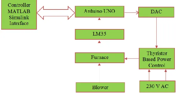
The experiment is conducted in a thermal process analyzer, it includes a thyristor controlled electric furnace and an air
blower. The air blower acts as a load variable in the process. The blower speed can be varied manually to introduce the
disturbance. The controlled variable is the furnace temperature and the manipulated variable is the control voltage, to the
thyristor-based power control system.
Fig. 1 Block diagram of thermal process control systems
The above mentioned experimental setup is the prototype of a thermal process. The control system block diagram for the
algorithm, which is present in the microcontroller. The temperature measurement is made with the help of LM35 precision
integrated-circuit temperature sensor. The output voltage of this sensor is linearly proportional to the Centigrade temperature
and the scale factor is 10mV per degree centigrade. The temperature range of this sensor is -55°c to 150°c. The measured
temperature is acquired with Arduino Uno which is a microcontroller based on the ATmega328.
A thyristor-based power control circuit is used to regulate the temperature of the furnace. The control voltage for the
thyristor-based power control circuit determines the temperature of the furnace by regulating the AC supply voltage using a
pulse width modulation method. The control voltage is obtained from the Arduino Uno. Typically the control voltage is an
analog signal. Since Arduino Uno supports only digital outputs an external Digital to Analog Convertor (DAC) is used. DAC
circuit is designed using DAC0808 which is an 8-bit monolithic digital-to-analog converter. The control voltage from DAC is
given to a thyristor-based power control for proper temperature regulation.
4.
Embedded Adaptive Controller
The possibilities of embedded controller implementation using Simulink are summarized in this section. The real-time
implementation of an adaptive controller using Simulink requires a target device. The various kinds of target devices
compatible with Simulink are micro controllers, Digital Signal Processors (DSP) and xPC Target. Most of the target devices
are costly and unbearable for a smaller level projects. The real-time control by xPC Target using Simulink is developed as
mentioned in [7] and [8]. The xPC Target devices are compatible with high-performance industrial computers. The DSP based
embedded platform provides the facility of model conversion from Simulink to real-time environment. It gives the flexibility
of an interfacing more number of peripheral devices. Among these target devices, microcontrollers are the cheapest device
used in an embedded system. In microcontroller category also various processors are available, some of the processors are
ATmega, ARM processors, etc. The ARM processor-based embedded adaptive controller is developed as presented in [9].
Arduino is one of the microcontrollers used for the development of embedded controllers. Control algorithm development by
Arduino Integrated Development Environment (IDE) is discussed in [10]. Through IDE, Arduino can be programmed using
embedded programming. The IDE based control algorithm development is a bit complex and time-consuming. The Simulink
model-based program is not possible with IDE. The Arduino support package facilitates the Simulink model-based
programming in Arduino.
In this paper, a control algorithm is implemented in Arduino Uno using the Arduino support package. The process
temperature is read by IC-based temperature sensor LM35. Arduino reads the temperature of the thermal system through its pin
number 1. Since the Arduino is having 10-bit Analog to Digital Convertor (ADC), the maximum ADC value is 1024 and the
reference is given 5V. The scaling has to be done properly to get the process temperature. As per the data sheet, the output of
LM35 is 10mV/ºc. The actual temperature is found by Eq. (1).
5
( C)
0.483
1024 0.01
out
out
V
T
V
(1)where 𝑉𝑜𝑢𝑡 is the output of LM35 in decimal equivalent.
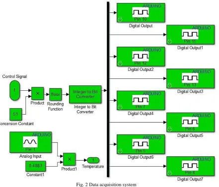
The equivalent temperature value is given to the control algorithm to compute the required control signal. The control
signal is sent to its digital output pins as shown in Fig. 2. The control signal generated is converted into 8-bit data and is given
to 8 digits write blocks. Integer to bit converter block demands only integer values, hence a rounding function is used before it.
The 8-bit conversion requires the multiplication of the control signal with constant so that the 0-5V will be converted to 0-255.
The multiplication constant 51 is chosen to convert 0-5 range to 0-255 range. The 8-bit digital outputs are sent to digital pins 4,
5, 6, 7, 10, 11, 12 and 13 of Arduino. The thyristor-based control circuit requires an analog voltage. Hence these digital signals
Fig. 2 Data acquisition system
4.1. Implementation of P, PI, and PID controllers
Fig. 3 P, PI & PID controllers using Simulink Arduino support package
The real-time implementation of P, PI and PID controllers using Simulink Arduino support package is shown in Fig. 3.
The developed control algorithm is downloaded into Arduino to work as a standalone controller. All the three control functions
are achieved using the same MATLAB subfunction by properly enabling the proportional, integral and derivative gains. The
setpoint is given to pin number 2 of the Arduino Uno using a potential divider circuit. This circuit provides the output in t he
range of 0-5V to pin number 2 of Arduino Uno. The provision for adjusting the setpoint is also properly scaled based on Eq (1).
The integral controller may experience the integral windup in real-time process control. The PID control algorithm includes the
anti-reset windup algorithm to reduce integral windup. The data acquisition system for the thermal process shown in Fig. 3 is
4.2. Development of mathematical model for the temperature process
The laboratory-based temperature process analyzer consists of a smaller size furnace. The operating region is in between
25°c to 80°c. Process reaction curve method is used to find the mathematical model of the process. The feedback in Fig. 3 is
removed. The initial steady state is noted. A step input of known magnitude is given to pin number 2 of the Arduino at time T1.
The time at which the process variable begins to change is noted as T2. The process variable is allowed to reach the new steady
state. The difference between T1 and T2 is the dead time of the process. The change in the process variable is computed by
subtracting the new steady state of the initial steady state. Time taken by the response to reach 63.2% of process variable
change is noted as T3. The time constant of the process is the difference between T3 and T2. The process gain is calculated by
dividing the magnitude of the final steady state by the magnitude of the change in step input. The derived model is a first-order
system with the dead time process. The model of the system is given in Eq. (2).
10
1.2
( )
55
1
se
G s
s
(2)4.3. Implementation of model reference adaptive control
Adaptive control is one of the widely used control strategies to design advanced control systems for better performance
and accuracy [11]. Model Reference Adaptive Control (MRAC) is a direct adaption strategy with an adjustable mechanism to
adjust controller parameters. The implementation of MRAC for the first order process is carried out as discussed in [12]. The
MRAC works on the principle of adjusting the control parameters so that the output of the actual plant tracks the output of a
reference model having the same reference input [13]. The implementation of MRAC and the design of adjustment
mechanisms are referred to from [14].
The reference model is used to give an ideal response of the adaptive control system to the reference input. The controller
is usually described by a set of adjustable parameters. In this paper two adjustable parameters, θ1 and θ2 are used to describe the
control law. Adaptive mechanism is used to alter the parameters of the controller so that the actual plant could track the
reference model. Mathematical approaches like MIT rule, Lyapunov theory, and theory of augmented error can be used to
develop the adjusting mechanism. Since the experimental thermal process is a first order system, MIT based MRAC for a first
order system is followed for the development of controllers.
The model of the temperature process and the reference model are given in Eqs. (3) and (4).
( )
G( )
( )
y s
b
s
u s
s a
(3)where
y
is the output from the process andu
is the control input to the process.( )
( )
( )
m m m c my s
b
G s
u s
s a
(4)where
y
mis the reference model output and the 𝑢𝑐 is the command signal to the reference model.The controller equation is given in Eq. (5).
1
c
-
2
u
u
y
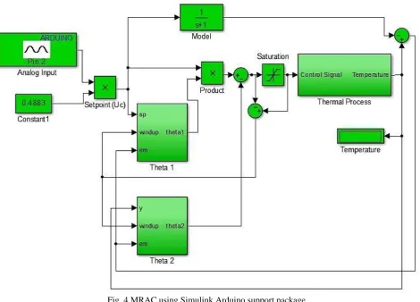
(5)Fig. 4 MRAC using Simulink Arduino support package
As per the MIT rule, the controller parameter has to be changed in the direction of the negative gradient of cost function J.
The cost function is chosen in this application is given in Eq. (6) and the rate of change of controller parameter is described in
Eq. (7) e
is known as sensitivity derivative.
2
1
2
J
e
(6)- '
- '
d
J
e
e
dt
(7)where
e
is the error given in Eq. (8).-
me
y y
(8)where
y
is the process output and it is described by Eq. (9). From Eqs. (3) and (5),y
is derived.1
2 c
b
y
u
s
a b
(9)The controller parameters are obtained from Eqs. (8) and (9). The denominators of sensitivity derivatives are approximated as
per Eq. (12).
1 2
c
e
b
u
s
a b
2 2
-
e
b
y
s a b
(11)2 m
s
a b
s
a
(12)The MIT rule is applied to determine the controller parameters. The sensitivity parameters given in Eqs. (10) and (11) are
substituted in Eq. (7) to find out the controller parameters. The parameters
b
anda
m are combined with adaptation gain
'
.The equations for updating the controller parameter
1 are given in Eqs. (13) and (14). Similarly, the other controllerparameter
2 is updated using Eqs. (15) and (16).'
1
-
-
mc c
m m
d
b
a
u
e
u
e
dt
s a
s a
(13)1
-
m c ma
u
edt
s a
(14)'
2 m
m m
d
b
a
y e
y e
dt
s a
s a
(15)2 m m
a
y edt
s a
(16)where
is the adaptation gain,u
c is command signal,e
is an error andy
is the measured process variable.Practical implementation leads to integral windup due to the integrator present in the equations. Hence anti-reset windup
is also included in the control algorithm. The reason for reset windup is the accumulation of the input to the integrator. The
accumulated value leads to the saturation of the controller output. The anti-reset algorithm helps to remove the integral windup.
The anti-reset windup procedure includes a saturation block, which limits the controller output. The controller output before
the saturation block is subtracted from the controller output after the saturation block. The subtracted output is added to the
input of the integrator. This procedure will not allow the integrator to accumulate its output. This procedure doesn’t have any
effect till the controller output is below the saturation value because the subtracted value before and after the saturation block is
zero. Once the controller output begins to increase from the maximum value, the anti-reset windup procedure will start
functioning. The same anti reset procedure is used in all the controller implementations described in this paper.
The controller implementation is shown in Fig. 4. The control signal from the algorithm is limited to 5V using the
saturation block in the Simulink. As shown in Fig. 2, this output from the saturation block is converted into corresponding
digital output. Using a DAC the digital output is converted to analog and given to the thyristor-based power control circuit to
control the furnace temperature.
4.4. Implementation of modified model reference adaptive control
In order to improve the transient performance of the control system, the MRAC scheme is modified [15]. In the modified
MMRAC, classical PID control action is also included. The modified controller output u is derived as per the Eq. (17). The
controller parameters
1 and
2have the same purpose similar to the MRAC. The MMRAC is developed by subtracting theeffect of PID controller action from the MRAC [16].
1 c
-
2-
p i dde
u
u
y
K e
K edt
K
dt
where
K
p,K
i andK
d are the proportional, integral and derivative gains for the PID controller.The optimal values of PID controller parameters are appropriately chosen to provide the best process regulations.
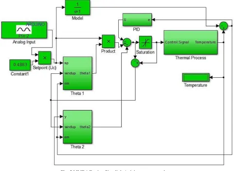
Fig. 5 MMRAC using Simulink Arduino support package
Even though many tuning procedures are available, choosing PID controller parameters is a challenging task for control
engineers, hence for a real-time process, control engineers prefer trial and error method [17]. The derivative action of PID
control improves the predictive nature of the control system and improves the speed of response. It predicts future controlled
output by computing the rate of change of error and accordingly takes the control action to minimize the error. The integral
action removes the offset in the controlled variable. The integral windup due to the integral action is removed by the anti-reset
windup procedure mentioned in the previous section. Hence the modified control scheme includes all the advantages of PID
control and MRAC. The integrator's used in the computation of
1 and
2also produces reset windup; hence the sameanti-reset windup procedure is followed to remove the integral windup.
The real-time implementation of the modified model reference adaptive controller is shown in Fig. 5. The control
algorithm is developed using Simulink Arduino support package. The real-time interface is developed by the help of Analog
input block and the digital output block. The data acquisition system for the thermal process analyzer is developed in the
subsystem as shown in Fig. 2. The setpoint of the standalone MMRAC is set with the help of the knob present in the hardware.
The value set by the user is read by the controller and it is properly converted into engineering units. The control algorithm
compares both the reference model output and the actual process output. The computed controller parameters force the process
to follow the reference model. The computation is based on Eq. (17) so that the change in the controller parameter minimizes
the error. According to the control algorithm, the desired control signal is sent to the thyristor-based power control circuit to
5.
Results and Discussion
The classical PID controller algorithm and model-based algorithm was developed in this research. Real-time
implementation using the microcontroller is simplified by this approach. The experimental setup shows the actual electric
furnace with a blower. The thyristor-based power control circuit, controller implementation using Simulink and the Arduino
Uno with the peripheral circuits are also depicted in Fig. 6. The control algorithms developed in this work are P controller, PI
Controller, PID Controller, MRAC and MMRAC. The required control algorithm was downloaded into the Arduino Uno
hardware. The electric furnace was allowed to settle at two different temperatures 40°c and 60°c. The controller performance
was observed by plotting the response of the temperature control system with respect to time. The transient performance of the
system is analyzed for all the controllers.
Fig. 6 Experimental setup
5.1. Controller observation and response
The following control algorithms P, PI, PID, MRAC, and MMRAC were implemented in real time. A comparative
analysis has been made using the available data. The temperature of the furnace is plotted in graphs with respect to time. The
response of the furnace for the setpoint of 40°c is shown in Fig. 7. Since the setpoint is 40°c and it is closer to the room
temperature, the process takes around 20 seconds to reach the setpoint. The rise time of the process varies with respect to the
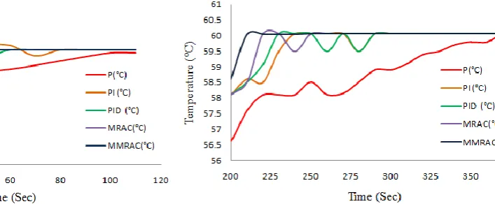
controllers used. The response of the furnace for the setpoint of 60°c is shown in Fig. 8. Since the process lag for the electric
furnace is considerably high, it takes around 200 seconds to reach the setpoint. The time from 200 seconds to 380 seconds is
used for the comparative analysis.
Fig. 7 Comparative response of furnace for 40°c setpoint Fig. 8 Comparative response of furnace for 60°c setpoint
5.2. Performance analysis
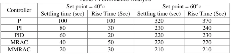
The performance of the controller is analyzed using the settling time. The tolerance limit for the settling time is 1%. The
controllers. The other performance metrics are not considered, because except for PI and PID controllers, other controllers
have very negligible oscillations or zero oscillations around the setpoint. So there is no overshoot or negligible overshoot for
Proportional Control, MRAC and MMRAC. The settling time of the process using MRAC and MMRAC, for the setpoint of
40°c is less than the rise time. The settling time and rise time are the same for the process using MRAC and MMRAC, for the
setpoint of 60°c. In all operating regions, MRAC and MMRAC respond quickly to the process parameter changes and take the
corrective action.
Table 1 Performance Analysis
Controller Set point = 40°c Set point = 60°c
Settling time (sec) Rise Time (Sec) Settling time (sec) Rise Time (Sec)
P 100 100 320 370
PI 80 30 230 240
PID 60 20 220 230
MRAC 40 50 220 220
MMRAC 20 30 210 210
6.
Conclusions
The Arduino open hardware platform is used as a low-cost data acquisition system and controller. P, PI, PID, MRAC, and
MMRAC are implemented in the Arduino microcontroller using MATLAB Simulink. The performance analysis is made in
terms of settling time. The developed embedded controller provides the platform to implement any type of complex control
algorithms. This will help in the field of process control to implement complex algorithms with low-cost devices. The
embedded based MMRAC controller shows better performance over the other controllers mentioned in this paper. Hence, the
system under study is best suited for MMRAC. This work may be extended by developing intelligent controller using the
Arduino microcontroller. Implementing complicated algorithms can be simplified by using the real-time interface developed in
this paper. Hence the proposed methodology will be beneficial to academic institutions and research organizations in testing
and implementing various sophisticated algorithms.
Conflicts of Interest
The authors declare no conflict of interest.
References
[1] T. Mushiri, A. Mahachi, and C. Mbohwa, “A model reference adaptive control system for the pneumatic valve of the bottle washer in beverages using Simulink,” Proc. International Conference on Sustainable Materials Processing and Manufacturing (SMPM 17), Elsevier, January 2017, pp. 364-373.
[2] B. M. Mirkin and Per-Olof Gutman, “Output feedback model reference adaptive control for multi-input-multi-output plants with state delay,” Systems & Control Letters, vol. 54, pp. 961-972, February 2005.
[3] R. A. Fahmy, R. I. Badr, and Farouk A. Rahman, “Adaptive PID controller Using RLS for SISO stable and unstable systems,” Advances in Power Electronics, vol. 2014, pp. 1-5, October 2014.
[4] R. A. Fahmy, R. I. Badr, and Farouk A. Rahman, “Adaptive PID controller Using RLS for SISO stable and unstable systems,” Advances in Power Electronics, vol. 2014, pp. 1-5, October 2014.
[5] K. K. McKee, Gareth L. Forbes, Ilyas Mazhar, Rodney Entwistle, and Ian Howard, “Low cost remote data acquisition system, ”Curtin University, Department of Mechanical Engineering, Technical Note, December 2013.
[6] S. Humayun, Maria Mehmood, and Faran Mahmood, “Developing a LabVIEW and MATLAB-based test bed for data acquisition, analysis and calibration of frequency generators over GPIB,” International Journal of Computer Applications, vol. 40, pp. 11-15, February 2012.
[7] Handbook of Networked and Embedded Control Systems. Birkhauser Boston, University of Maryland, 2008.
[8] D. Hercog, A. Rojko, M. Curkovic, B. Gergic, and K. Jezernik, “Embedded platform for rapid implementation of local and remote motion control experiments,” Przeglad Elektrotechniczny, vol. 87, pp. 73-76, March 2011.
[10] A. M. El-Nagar, “Embedded intelligent adaptive PI controller for an electromechanical system,” ISA Transactions, vol. 64, pp. 314-327, September 2016.
[11] Ioana Nascu, Ioan Nascu, and G.Vlad, “Predictive adaptive control of an activated sludge wastewater treatment process,” Advances in Technology Innovation, vol. 1, pp. 38-40, March 2016.
[12] M. P. R. V. Rao, “New design of model reference adaptive control systems,” Journal of Applied Mechanical Engineering, vol. 3, pp. 1-3, January 2014.
[13] S.H. Rajani, B. M. Krishna, and U. Nair, “Adaptive and modified adaptive control for pressure regulation in a hypersonic wind tunnel,” International Journal of Modelling Identification and Control, vol. 29, pp. 78-87, March 2018.
[14] K. J. Astrom and B. Wittenmark, “Adaptive control,” 2nd Ed. New York: Dover Publications Inc., 2013. [15] S. Zhang and S. Dian, “Controller design for compound pendulum with PID and MRAC switch control,” Proc.
International Conference on Automation Control and Robotics Engineering (CACRE 2018), IOP Publishing, July 2018, pp. 1-5.
[16] R.J. Pawar and B.J. Parvat, “MRAC and modified MRAC controller design for level process control,” Proc. Indian Control Conference (ICC 18), IEEE Explore, January 2018, pp. 217-222.
[17] L. Guessas and K. Benmahammed, “Adaptive backstepping and PID optimized by genetic algorithm in control of chaotic,” International Journal of Innovative Computing Information and Control, vol. 7, pp. 5299-5312, September 2011.
Copyright© by the authors. Licensee TAETI, Taiwan. This article is an open access article distributed under the terms and conditions of the Creative Commons Attribution (CC BY-NC) license