30
International Journal of Engineering and Management Research, Volume-3, Issue-3, June 2013
ISSN No.: 2250-0758
Pages: 30-35
www.ijemr.net
Minimization of Effect of Time Delay Spread on Radio Communications
with Channel Adaptive Gain and Phase Adjustment Mapper
Shailendra Singh1, Saurabh Chandra2
1
Department of Electronics & Communication Engineering, Integral University, Lucknow, INDIA.
2
Electronics & Communication Engineering, Integral University, Lucknow, INDIA.
ABSTRACT
In this paper, we present an adaptive channel estimation scheme for IEEE 802.16-2004 Wireless Metropolitan Area Network. The scheme is combined with time domain channel equalization. The simulation results and performance of proposed method can satisfy the BER requirement of IEEE 802.16-2004 standard in the non-line-of-sight environment with the highest data rate (20MHz) transmission. We have also found that when the channel is slow fading, the channel estimation inside the block can be updated using the decision feedback equalizer at each sub-carrier.
Keywords---IEEE 802.16-2004, WIMAX, BER, WMAN,
Equalizer, QPSK, BPSK.
I.
INTRODUCTION
WiMAX (Worldwide Interoperability for Microwave Access) is defined for broadband wireless access (BWA).It is increasingly gaining interests as an alternative “last-mile” technology to DSL lines and cable modems.
It is the best candidates for wireless links between Wireless Local Area Networks (WLAN) and the Internet. It specifies channel bandwidth from 1.75MHz up to 20MHz and cell distance up to 30 miles.
Wireless communication systems usually suffer from frequency selective and time variant channel. Orthogonal Frequency Division Multiplexing (OFDM) technique is widely adopted in those systems due to its robustness against multipath fading and simpler equalization scheme.
In most of applications, for retaining the orthogonality of subcarriers and overcome inter symbol interference (ISI), a cyclic prefix (CP) is inserted instead of simply inserting guard interval. If the maximum delay of the multipath channel does not exceed the CP length, the OFDM system would be ISI free by removing the guarding interval. For WiMAX systems, its delay spread is
typically over several micro-seconds which is easily longer than the guarding interval. Therefore, it is very challenging to maintain the system BER performance for non-line-of-sight (NLOS) channels at high data rate transmission with high bandwidth (e.g. 20MHz) since high sampling rate is needed.
To reduce the effect of inter symbol interference (ISI) caused by the dispersive Rayleigh-fading environment [1], the symbol duration must be much larger than the channel delay spread. In orthogonal frequency-division multiplexing (OFDM) [2]–[6], the entire channel is divided into many narrow sub channels, which are transmitted in parallel, thereby increasing the symbol duration and reducing the ISI. Therefore, OFDM is an effective technique for combating multipath fading and for high-bit-rate transmission over mobile wireless channels. To eliminate the need for channel estimation and tracking, differential demodulation can be used in OFDM systems, at the expense of a 3–4-dB loss in signal-to-noise ratio (SNR) compared with coherent demodulation. Accurate channel estimation [3], [4], [5] can be used in OFDM systems to improve their performance by allowing for coherent demodulation. Furthermore, for systems with receiver diversity, optimum combining can be obtained by means of channel estimators. In [3], [4], and [5], a channel estimator for OFDM systems has been proposed based on the singular-value decomposition or frequency-domain filtering. Time-domain filtering has been proposed in [5] to further improve the channel estimator performance. However, the best time- or frequency-domain filtering shapes for channel estimation has not been studied.
In this paper we investigate channel estimation for OFDM systems. We first derive the estimator, which makes full use of the correlation of the channel frequency response at different times. Computer simulation demonstrates that the performance of OFDM systems using coherent demodulation based on our channel estimator can be significantly improved.
31
II.
SYSTEM DESCRIPTION
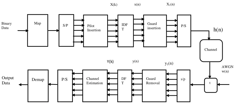
The OFDM system based on pilot channel estimation is given in Fig. 2. The binary information is first grouped and mapped according to the modulation in “signal mapper”. After inserting pilots either to all sub-carriers with a specific period or uniformly between the information data sequence, IDFT block is used to transform the data sequence of length into N {X(k)} time domain signal {x(n)} with the following equation:
x(n)=IDFT{X(k) n=0,1,2,3……,N – 1
=
Where N is the DFT length. Following IDFT block, guard time, which is chosen to be larger than the expected delay spread, is inserted to prevent inter-symbol interference. This guard time includes the cyclically extended part of OFDM symbol in order to eliminate inter-carrier interference (ICI).
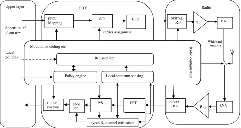
Figure 1. OFDM-based CR system block diagram.
The resultant OFDM symbol is given as follows:
Where Ng is the length of the guard interval. The
transmitted signal xf(n) will pass through the frequency
selective time varying fading channel with additive noise. The received signal is given by:
Where w(n) is Additive White Gaussian Noise (AWGN) and h(n) is the channel impulse response. The channel response can be represented by [5]:
h(n)= 0≤n≤N-1
where r is the total number of propagation paths, hi is the complex impulse response of the ithpath, fDi is the ith
path Doppler frequency shift, λ is delay spread index, T is the sample period and Ti is the ith path delay normalized
by the sampling time. At the receiver, after passing to discrete domain through A/D and low pass filter, guard time is removed:
for –
n=0,1,2….N-1
Then y(n) is sent to DFT block for the following operation:
Y(k)=DFT{y(n)} k=0,1,2…..N-1
=
Upper layer
Spectrum inf From n/w
Local policies
Sub
carrier assignment
Radio PHY
FEC/ Mapping
S/P IFFT DIGITAL
RF DA C PA
LNA
AD C
DIGITAL
RF
FFT
P/S enco
der FEC/de
mapping
Modulation coding etc Ra
di
o c
onf
igur
a
tio
n
Decision unit
Policy engine Local spectrum sensing
FFT
synch.& channel estimation
32
Assuming there is no ISI, [8] shows the relation of the resulting Y(k) to H(k) = DFT{h(n)}, I(k) that is ICI because of Doppler frequency and W(k) = DFT {w(n)}, with the following equation [4]:
Y(k)=X(k)H(k)+I(k)+W(k) k=0,1,2….,N-1
Where
H(k)=
I(k)=
.
Following DFT block, the pilot signals are extracted and the estimated channel for the data sub-channels is obtained in channel estimation block. Then the transmitted data is estimated by:
= k=0,1,2….,N-1
Then the binary information data is obtained back in “signal demapper” block.
Figure 2: Baseband OFDM system. S/P indicates signal and pilot data.
III. CHANNEL ESTIMATION BASED ON
BLOCK-TYPE PILOT ARRANGEMENT
In block-type pilot based channel estimation, OFDM channel estimation symbols are transmitted periodically, in which all sub-carriers are used as pilots. If the channel is constant during the block, there will be no channel estimation error since the pilots are sent at all carriers. The estimation can be performed by using either LS or MMSE [2], [3].
If inter symbol interference is eliminated by the guard interval, we write (7) in matrix notation
Y = XFh + W
Where
X=diag{X(0),X(1),…,X(N-1)} Y=
W=
H= =
F=
If the time domain channel vector is Gaussian and uncorrelated with the channel noise W, the frequency domain MMSE estimate of h is given by [3]:
Y
Where
are the cross covariance matrix between h and Y and the auto covariance matrix of Y. Rhh is the auto-covariance
matrix of h and σ2 represents the noise variance
E{|W(k)|2}. The LS estimate is represented by:
Map
S/P
Binary
Data Pilot
Insertion
IDF T
Guard insertion
P/S
Channel
t
Demap Guard
Removal
P/S
s/p Channel
Estimation
DF T
AWGN w(n)
h(n)
X(k) x(n) X1(n)
y1(n)
y(n) Y(k)
33
which minimizes
,
When the channel is slow fading, the channel estimation inside the block can be updated using the decision feedback equalizer at each sub-carrier. Decision feedback equalizer for the sub-carrier can be described as follows:
• The channel response at the sub-carrier estimated from the previous symbol {Hc(k)} is used to find
the estimated transmitted signal {Xc(k)}.
k=0,1,….,N-1;
• {Xc(k)} is mapped to the binary data through
“signal demapper” and then obtained back through “signal mapper” as {Xpure(k)}.
• The estimated channel Hc(k) is updated by:
k=0,1,2….N-1.
Since the decision feedback equalizer has to assume that the decisions are correct, the fast fading channel will cause the complete loss of estimated channel parameters. Therefore, as the channel fading becomes faster, there happens to be a compromise between the estimation error due to the interpolation and the error due to loss of channel tracking. For fast fading channels, as will be shown in simulations, the comb-type based channel estimation performs much better.
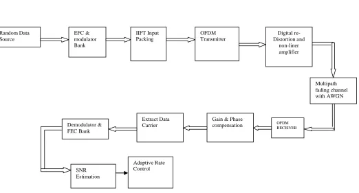
Figure 3: Simulink model for adaptive IQ mapper
IV.
SIMULATION RESULTS
We have performed channel estimation for adjusting gain and phase at different IQ mapping scheme to find the BER at different SNR of the AWGN channels. All simulation are performed using Matlab.The evaluation is performed in two modes. In mode 1 we used only channel estimation for gain and phase adjustment in a noise Rayleigh fading scheme. In mode 2 we applied adaptive equalization to switch over the IQ mapping scheme at different SNR as per changes in fading channel time response.
Mode 1: Channel Estimation for gain and phase adjustment-
Simulink model is used for estimation and equalization is shown in fig.3.For testing the estimator performance at different IQ map scheme we find BER vs. SNR values given in Table 1.The parameters that are used for fading channel are
Fading mode: Frequency selective fading K-Factor: 0.5,
Delay Vector(s): [0 0.4 0.9]*1e-6 & Gain Vector (dB): [0 -5 -10]
Multipath fading channel with AWGN
Extract Data Carrier
Gain & Phase
compensation OFDM RECEIVER Demodulator &
FEC Bank
SNR Estimation
Adaptive Rate Control Random Data
Source
EFC & modulator Bank
IIFT Input Packing
OFDM Transmitter
Digital re-Distortion and
34
SNR is varied from 1 to 40 dB and BER is calculated for BPSK 1/2, QPSK1/2, QPSK3/4 and QAM 16 mappers individually under the effect of channel estimator.
For table 1 it can be demonstrated that lowest SNR is obtained at BPSK1/2.QPSK1/2 is also better mapper in comparison to QPSK3/4 and QAM16.
TABLE I
SNR BPSK 1/2 QPSK 1/2 QPSK 3/4 QAM 16
1 BER =0.16 BER=.50 BER=.49 BER=.49
5 0.00024 0.3015 0.44 0.49
10 0 0 0.056 0.49
15 0 0 0.0004 0.393
20 0 0 0 0.001
25 0 0 0 0
30 0 0 0 0
35 0 0 0 0
40 0 0 0 0
Mode 2: Adaptive Equalizer with Channel estimation-
In mode 2 we performed an adaptive decision block that can change the IQ mapping scheme as per the minimum value of BER.The test is performed by pilot data to make calculation of BER inserted along with signal data.
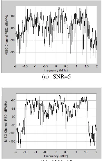
(a) SNR=5
(b) SNR=15
(c) SNR=25
(d) SNR=35
Figure 4:Spectrum scope at different SNR for mode 2.
Figure 4 (a,b,c,d) indicates spectrum scope at receiver end at different SNR using adaptive decision based mapper performance.At SNR 5(fig 4a) however the fadding effect has distorted the specturum so much that the signal changes can not be recovered using phase and gain adjustment but the spectrum at and above 15 are similar and show less distortiopn (fig 4b,c,d) however these details can be easily visualized using the scatter plot as shown in figure 5.
35
(b) SNR = 15
(c) SNR =25
(d) SNR= 35
Figure 5: Scatter plot at different SNR.
From figure 5 it can be seen that scatter in the symbols are least after the SNR =15 dB hence it clearly demonstrates that adapitive decsion has chosen QAM 16 for performing the symbol mapping at high SNR but for low SNR BPSK is best suited(fig a).
TABLE II SNR Vs BER
SNR BER Total Bits
1 .5 1680
4 .4998 1680
7 .4940 1680
10 .4613 1680
13 .2130 1680
16 .0130 1680
19 0 1680
22 0 1680
25 0 1680
28 0 1680
30 0 1680
Table II indicates the BER vs SNR values of our model for mode 2.
V.
CONCLUSION
It can be concluded that in the presence of channel fading there is no definite mapping scheme that can be universally associated at every time. If the SNR is also considered along with the fading than at low SNR BPSK ½ is best choice but at higher SNR QAM 16 out perform than BPSK By using estimation we can recover the signal with low BER by adjusting gain and phase causing during channel fading.Adaptive equalizer is good choice for SNR above 15 db.
REFERENCES
[1] J. C.-I. Chuang, “The effect of time delay spread on portable radio communications channels with digital modulation,” IEEE J. Select. Areas Commun. Vol. SAC-5, pp. 879–889, June 1987.
[2] L. J. Cimini, Jr., “Analysis and simulation of a digital mobile channel using orthogonal frequency division multiplexing,” IEEE Trans. Commun., vol. COM-33, pp. 665–675, July 1985.
[3] J.-J. van de Beek, O. Edfors, M. Sandell, S. K. Wilson, and P. O. B¨orjesson, “On channel estimation in OFDM systems,” in Proc. 45th IEEE Vehicular Technology Conf., Chicago, IL, July 1995, pp. 815–819.
[4] “OFDM channel estimation by singular value decomposition,” in Proc. 46th IEEE Vehicular Technology Conf., Atlanta, GA, Apr. 1996, pp. 923–927.
[5] V. Mignone and A. Morello, “CD3-OFDM: A novel demodulation scheme for fixed and mobile receivers,” IEEE Trans. Commun., vol. 44, pp. 1144–1151, Sept. 1996.