99
Design and Analysis of Snap fit joint in Plastic Part
Shweta Deshmukha and A.U. Awateb
aM.E.(CAD/CAM),Mech. Eng Dept,PRMITRA,Amravati
b Professor, Mech. Eng. Dept, PRMITRA,Amravati
ABSTRACT:
New products drive business. To remain competitive, industry is continually searching for new methods to evolve their products. To address this need, we use reverse engineering methodology. We start by formulating the customer needs, followed by reverse engineering, creating a functional model through teardowns. The functional model leads to specifications that match the customer needs. Depending upon required redesign scope, new features are possibly conceived, or not. Next, models of the specifications are developed and optimized. The new product form is then built and further optimized using designed experiments. In this research paper, we apply reverse engineering process on spur gear by doing computer aided modeling, design and analysis.
Reverse engineering is based on the analysis of point clouds acquired through coordinate measuring devices, such as, Coordinate Measuring Machines (CMMs), Optical Scanners. Duplicating the part is done with the help of CMM and CAD/CAM software like Mastercam, Pro-engineer (Creo 1.0/2.0) etc. CMM is used to digitize the mechanical object. Taking coordinates (scan data) of the various points on the surface of the object and converting it into IGES file and using the same in the CAD/CAM software with required interfacing creates a surface or solid model of the object. Finally this solid model is used to generate CNC part program to manufacture the part on CNC Machining center.
Keywords: Reverse Engineering, Segmentation.
INTRODUCTION
We apply the reverse engineering process on spur gear by doing computer aided modeling, design and analysis. Objectives
1. To find out unknown dimensions of the spur gear because no part drawing is available. 2. To scan the spur gear with the help of CMM.
3. To prepare the CAD model. 4. To prepare part drawing. 5. Error analysis.
6. To analyze the component. 7. To generate NC part program.
8. To prepare inspection program for future purpose. The Study Component
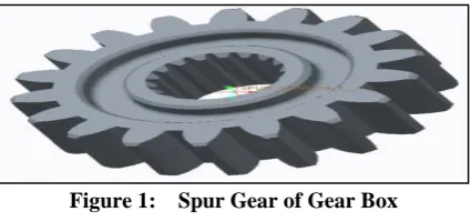
The component selected for project work is Spur Gear of Gear box of Rotavator. Spur Gear is a rotating machine part having cut teeth.
Figure 1: Spur Gear of Gear Box
METHDOLOGY:REVERSEENGINEERING
Volume 2, Special Issue 1 MEPCON 2015
100 Figure 2: Environment of Reverse Engineering
COORDINATEMEASURINGMACHINE
The machine will read the input points from the touch probe by touching the required location, as directed by the operator or programmer.
The machine then uses the X,Y,Z coordinates of each of these points to determine size and position. Then the measured dimensions can be determined by those points.
These points are collected by using a probe that is positioned manually by an operator or automatically via Direct Computer Control (DCC) is PCDMIS(PC Dimensional Measuring Interface Standard.). PCDMIS can be programmed to repeatedly measure identical parts.
Figure 3: Digitizing Process of CMM
CONVERSION OF PCDMODEL TO CADMODEL
The CMM used here has a PC-DMIS software pack for converting the data into polyline IGES format as small segments.(IGES stands for Initial Graphic Exchange Specification)
The polylines are then converted into curves/splines and this will reduce the curve generating process. By using this technique we get PCD which is then imported in CAD software.
The software used here for modeling purpose is Creo Parametric.It is CAD/CAE/CAM integration software of PTC Systems.
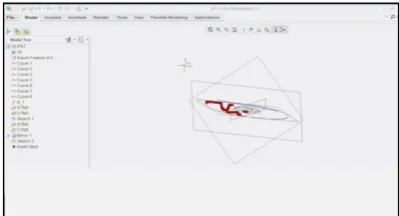
101 Figure 5 : Surface Model of spur gear in Creo Software
Figure 6 : Solid Model of spur gear in Creo Software
ANALYSIS OF SPUR GEAR
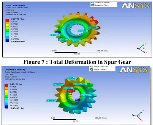
Finite element analysis (FEA) is a technique which is widely used to analyze stress-strain states in various portions of devices under inspection.
Figure 7 : Total Deformation in Spur Gear
Volume 2, Special Issue 1 MEPCON 2015
102 Figure 9: Equivalent (von-Mises) Stress
Figure 10: Normal Stress Stress on Spur Gear
Table 1: Analysis results for Spur Gear
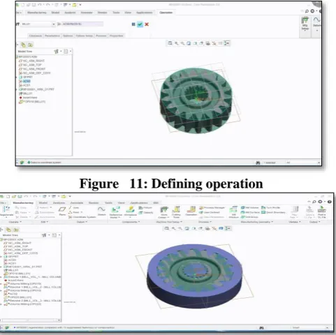
CAM MACHINING PROCESS USING CREO SOFTWARE
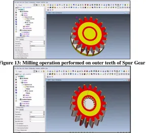
The development of CAM Model of Spur Gear by using of Creo software. Defining CNC machining operation i.e. Volume milling operation for spur gear. Defining and Setting parameters of top groove volume ,bottom groove volume, Defining machine used for manufacturing.
Finally, we get output file which is generated automatically in the machine readable format generally in NC coding which used G-Preparatory and M-Miscellaneous code.By exporting this file on CNC machine we can manufacture same product.
103 Figure 13: Milling operation performed on outer teeth of Spur Gear
Figure 14: Milling operation performed on Inner teeth of Spur Gear
Figure 15 : Final Simulation of Volume milling machining operation
Volume 2, Special Issue 1 MEPCON 2015
104 Figure 16: Flow Chart of research work
CONCLUSION
By using above stated methodology and objectives ,I studied computer aided modeling ,design and analysis of Spur Gear is completed.
The 3D CAD model of existing Spur Gear has been developed by using software Creo Parametric. After getting the solid model, we performed the Flexible Dynamic analysis in Ansys for a velocity of
0.2669 rad/sec then we got von misses stress 3.399 Mpa.
After that, we generated part drawing and by defining tool path, machining operation we got graphical simulation of given spur gear as well as NC part programming is generated automatically.
Application of Reverse Engineering using CMM , any product can be quickly captured in digital form, re-modeled, and exported for analysis and we can decide designed product is appropriate for use or not. In this way, reverse engineering process helps me to study component like spur gear.
REFERENCES
[1] Andrzej WERNER ―Coordinate measurements of free-form surfaces in reverse engineering process‖ acta mechanica et automatica, vol.4 no.4 (2010).
[2] Bardell R., V. Balendran, and K. Sivayoganathan, "Accuracy Analysis of 3D Data Collection and Free-Form Modeling Methods", Journal of Materials Processing Technology, 133, pp. 26-33, 2003.
[3] Belarifi F., E. Bayraktar, A. Benamar., ( 2008), _ The reverse engineering to optimise the dimensional conical spur gear by CAD _, Journal of Achievements in Materials and Manufacturing Engineering Volume 31. [4] CAD/CAM Theory and practice by Ibrahim Zeid, R Sivasubramanian second edition (2009), Chapter 13 part
programming and manufacturing, page no.699, publication
[5] Tata McGraw.Cheng Z.Q., J.G. Thacker, W.D. Pilkey; W.T. Hollowell, S.W. Reagan, E.M. Sieveka ―Experiences in reverse-engineering of a "Finite element automobile crash model”
[6] Elsevier Science Finite Elements in Analysis and Design 37 (2001) 843–860. Ismail A.R., Y. C. Soon, S. Abdullah, R. Zulkifli, K. Sopian and M.N.A. Rahman., (2009), _ Reverse Engineering in Fabrication of Piston Crown _ , European Journal of Scientific Research, Vol: 29 No.1, pp. 136-146.
[7] Manzoor Hussain M., Sambasiva Rao CH.and Prasad K. E. ―Reverse engineering: point cloud generation with cmm for part modeling and error analysis‖ ARPN Journal of Engineering and Applied Sciences VOL. 3, NO. 4, AUGUST 2008.
[8] Mohammad Shadab, Dr. Suhaib and Dr. R.A.Khan.‖Reverse engineering of Hero Honda CBZ Motorbike using Catia V5‖, National Conference on Recent Developments and Future Trends in Mechanical Engineering (2006). [9] Ngozi Sherry Ali., (2005), R Reverse Engineering of Automotive Parts Applying Laser Scanning and
Structured Light Techniques R , Thesis, the University of Tennessee, Knoxville.
105 [15] Xie, Z., Wang, J. & Zhang Q., 2005, Complete 3D measurement in reverse engineering using a multi-probe
system. International Journal of Machine Tools & Manufacture, 45: pp. 1474- 1486.
[16] Zhang Y., "Research into the engineering application of reverse engineering technology", Journal of Materials Processing Technology, Vol. 139, pp. 472-475, 2003.