46
Available online at www.ijiere.com
International Journal of Innovative and Emerging
Research in Engineering
e-ISSN: 2394 - 3343 p-ISSN: 2394 - 5494
Design and Simulation of Dual Band Microstrip Array Antenna
for IRNSS Receiver
Kshatriya bhavna
1Anil K. Sisodia
21,2Department of Communication System Engineering
1,2L. J. Institute of Engineering and Technology, Gujarat Technological University,
Ahmedabad, Gujarat
Abstract- Every country wants to be independent for satellite navigation systems for the positioning and other secured services. This requirement gave rise to the birth of IRNSS, constellation of 7 satellite serving 24x7 positioning and secured services. Normally receiver antenna for navigation is designed for large beam width and low gain. However IRNSS constellation in geostationary orbit, hence gain can be increased even beam is reduced is the motivation in designing array antenna for higher gain. And restructuring of micro strip patch antennas in array configuration gives the extra ability of antenna in term of gain enhancement. The aim of this Dissertation is to design and simulate 2x2 Microstrip patch array antenna for IRNSS Receiver at 2.49GHz and 1.176GHz using ADS Software.
Key words: Microstrip patch, array, IRNSS, fr4,ADS
I.INTRODUCTION
The IRNSS is Indian Regional Navigational Satellite system which is developed by the ISRO(Indian Space Research Organization) and it would be under complete control of the Indian Government[4]. The reuirement of such system is needed because in the hostile suitation to have access of foreign government controlled GPS is not guarnteed.[4] IRNSS Satellites operate on the L5 band (1.176GHz) and S band (2.49GHz). The overall constellation consists of seven satellites, of which three will be in GEO stationary and four in GEO synchronous orbits[6]. The IRNSS would provide two services one for civilian users and another one for military users and This system will be used for surveying, telecommunication, transport, identifying disaster locations and public safety[4]. All the satellite in the constellation is placed in Geo-stationary or Geo-synchronous orbit. All the satellites are visible from the user’s location unlike the G.P.S. system[6]. Hence the receive antenna need not be omnidirectional instead of only need of higher directivity and higher gain for the fixed object[6]. By the array antenna we can reduce the beam width of antenna, and this will enhance gain for the antenna and signal strength will be more[1].
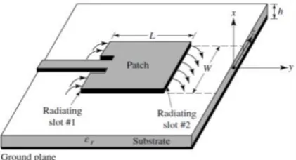
II.INTRODUCTION TO PATCH
The patch of a microstrip antenna is usually made of a conducting material. The patch is parallel to the ground plane[8]. In between the patch and the ground plane there is substrate with a dielectric constant whose value depends on the substrate used[3]. Patch antennas are low profile, simple, easy to fabricate. Within these advantages it has disadvantages of low fain and directivity hence overcome this problem instead of using single element a array can be form[7]. Arrays are considered to be very versatile and are used to synthesize a required pattern that is difficult to obtain using a single patch.[3]The results also show that patch array help in increasing the directivity, gain[7]. In this paper designs of 2x2 array operating at 1.16GHz and 2.49GHz, for IRNSS is shown.
47 A. Introduction To Antenna Factor:
Array factor determines the overall radiation pattern of array and the elements pattern describes radiati0n pattern of indivdual element[6]. array factor is defined by the function of total number of elements and pacing between them and the phase difference between the each element[6].
The radiation pattern of antenna array can be calculated by the
Array pattern=array element patterns*array factor
Array factor for N elements is given by
(AF)n= 1
N[ sin(N2φ)
sin(12φ)]
Array is classified as
1. Broadside Array
In broadside array maximum radiation of an array directed normal to the axis of the array[8]. Directivity for broadside array is given by,
2. End Fire Array
It is similar to the broadside array only the difference is that signals are out of phase in this and maximum radiation of an array is directed along the axis of the array.
Directivity is given by,
3. Planar Array
Individual radiators can be positioned along a rectangular grid to form a rectangular or planar array[8]. Planar array can be used to scan the main beam of antenna toward any point in space accordingly application including communication, tracking radar, search radar,etc.
𝐴𝐹 = {1 𝑀
𝑠𝑖𝑛 (𝑀2𝜑𝑋)
𝑠𝑖𝑛 (𝜑2𝑋) } { 1 𝑁
𝑠𝑖𝑛 (𝑁2𝜑𝑦)
𝑠𝑖𝑛 (𝜑2𝑦) }
Equation indicates that the pattern of a rectangular array is the product of the array factors of the arrays in the x and y‐ directions.
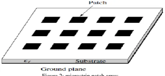
Figure 2: microstrip patch array
III. ANTENNA DESIGN
The goal of designing a microstrip array antenna is to improve gain and directivity for IRNSS. There are various important steps in designing
48 Table 1: Design specification
frequency 1.176GHz and 2.49GHz
Dielectric constant 4.3 Substrate height 2.5mm Copper thickness 0.035mm
Loss tangent 0.001
Equations for calculating width and length of patch is given by,
Calculations of width
w = c
2fr√ϵr
+1 2
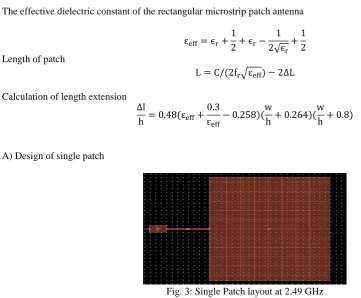
The effective dielectric constant of the rectangular microstrip patch antenna
εeff= ϵr+
1 2+ ϵr−
1 2√ϵr
+1 2 Length of patch
L = C/(2fr√εeff) − 2∆L
Calculation of length extension ∆l
h = 0.48(εeff+ 0.3 εeff
− 0.258)(w
h + 0.264)( w
h+ 0.8)
A) Design of single patch
Fig. 3: Single Patch layout at 2.49 GHz
In the figure 3 single patch layout at 2.49GHz frequency is shown. In which to match impedance of 50 ohm line with patch in middle a quarter wave line is used.
Fig. 4: RL Curve of Antenna at 2.49 GHz
49 B) Design of Single Patch
Fig. 5: Single Patch layout Simulation Results at 1.176GHz
Fig. 6: RL Curve of Antenna at 1.176 GHz
C) Design of 1x2 Array
Fig 7:1x2 Layout
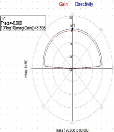
The fig 7 shows the layout of 1x2 array for the dual band in which one patch resonates at the 1.176GHz frequency having the patch width and length of patch 76.2 mm and 55.4 mm and other is at 2.49GHz having the width and length of patch of 35.6mm and 80.4mm.
50 As shown in the figure 8 and 9 obtained return loss at the frequency 1.176GHz is -17.191 dB and at 2.49GHz is -24.402 dB and achieved gain is 3.396dBi.
Fig. 9: Gain Plot of 1x2 Array
D) Design of 2x2 Array
Fig 10: 2x2 Array Layout
The below figures shows the return loss characteristics and gain plot of 2x2 array. As shown in the figure the achieved return loss by 2x2 arrays at the 1.176GHz is -17.748 dB or at 2.49GHz is – 24.876dB. Achieved gain is 4.451dBi
51 IV. CONCLUSION
I have designed and simulated single patch, 1x2 and 2x2 array for 1.176 and 2.49Ghz frequency, And as per the results we can say that as increasing number of patch, we can increase gain as well as directivity.
REFERENCES
[1] Dong-Fang Guan, Ying-Song Zhang, Zu-Ping Qian, Yujian Li, Wenquan Cao, and Feng Yuan, “Compact Microstrip Patch Array Antenna with Parasitically Coupled Feed”, IEEE Transactions on Antennas and Propagation,vol 64, 2016.
[2] Chao Sun, Huili Zheng, and Ying Liu, “Analysis and Design of a Low-Cost Dual-Band Compact Circularly Polarized Antenna for GPS Application.” IEEE Transanctions on Antenna And Propogation, vol. 64, no. 1, Januray 2016.
[3] Sergiy Y. Martynyuk,, 1Dmytro O. Vasylenko, Fedir F. Dubrovka and Anatoliy G. Laush, “A Novel Dual Band Microstrip Antenna Array For Receving of Satellite Navigational Signals GPS/GLONASS/GALILEO”. IEEE International Conference on Antenna Theory and Techniques, 2015, Kharkiv, Ukraine.
[4] B Sandhya Reddy, V Senthil Kumar, V V Srinivasan, Yateendra Mehta , “Dual Band Circularly Polarized Microstrip Antenna for IRNSS Reference Receiver”. IEEE International Microwave and RF Conference (IMaRC) 2015
[5] S. H. S. Esfahlani, A. Tavakoli, and P. Dehkhoda, “A Compact Single-Layer Dual-Band Microstrip Antenna for Satellite Applications,” IEEE Antennas and Wireless Propogation Letters,vol.10,2011.
[6] Falguni K. Makwana1,Anil K. Sisodia,” Design, Simulation and Development of 2x2 Microstrip Patch Array Antenna for Ranging Transponder in IRNSS,” International Journal for Scientific Research & Development,vol 4,2016.
[7] Shivani Singh1, Neha Tyagi2, Niti Sinha, “Design and Analysis of Single Patch, 2X1 and 4X1 Microstrip Antenna Arrays”.International Conference for Convergence of Technology – 2014.