A Modified Hybrid MoM-Modal Method for Shielding
Effectiveness Evaluation of Rectangular Enclosures with
Multiple Apertures
V. Rezaeii, R. Moinii٭, S. H. H. Sadeghii and F.Rachdiii
i V. Rezaei (e-mail: [email protected]),* Corresponding Author, R Moini (corresponding author to provide phone: +98-21-6646-6009, fax: +98-21-6640-6469, e-mail: [email protected]), and S. H. H. Sadeghi (e-mail: [email protected]) are with the Electromagnetics Research Laboratory of Amirkabir University of Technology, 424 Hafez Ave., Tehran 15914, Iran.
ii F.Rachdi Electromagnetic Compatibility Laboratory, Swiss Federal Institute of Technology (EPFL), Lausanne, Switzerland
ABSTRACT
A new hybrid modal-moment method is proposed to calculate fields penetrated through small apertures on rectangular metallic enclosures. First, the method of moments is used to numerically solve the governing electric field integral equation for the equivalent two-dimensional surface-current distributions on the surface of metallic enclosure including any number of rectangular apertures of arbitrary lay-out. The resultant exterior scattered fields are then used as the input to a testing procedure to obtain aperture field distributions in the modal expansion technique. These fields can be directly transferred to interior penetrated fields, using appropriate Green’s function of the cavity inside region. To validate the method proposed in this paper, the results of the proposed method are compared with the measurement results available in the literature and those obtained using the conventional modal-moment method for both single and double aperture enclosures. It is shown that the proposed method offers a remarkable improvement in computation burden over the conventional method, especially for calculation of field penetration through much number of apertures typical to realistic measures in the discipline of electromagnetic compatibility.
KEYWORDS
Shielding effectiveness, Hybrid methods, Electric field integral equation, Rectangular enclosures, Rectangular apertures.
1. INTRODUCTION
Shielding refers to the initiatives in the field of electromagnetic compatibility (EMC) to protect sensitive equipments or biological bodies against external electromagnetic interferences or to prevent radiation of electromagnetic fields to the surrounding medium [1]. Suitability of the shield is usually measured through a quantity named as shielding effectiveness (SE) which is the ratio of the magnitude of the electric (magnetic) field at the absence of the shield to the magnitude of the electric (magnetic) field at the presence of the shield. A general solution of the shielding problem can be sought through the use of various numerical and analytical techniques. Analytical, semi-analytical, and approximate techniques provide straightforward solutions only for very simple lay-outs or limited frequency range and are applicable to specialized problems of shielding [2]-[5].
Numerical methods, on the other hand, can be used for any complex structure but at the expense of computational speed and memory usage. Most work in this field has been carried out using the finite element method (FEM) [6], the finite difference time-domain (FDTD) method [7], [8], the modal method of moments (MoM) [9]-[11], the moment method solution of integral equation [12], [13], the transmission line matrix (TLM) method [14], [15], and the circuit theory or analogous transmission line methods [16].
of electromagnetic fields at any point within the solution domain. Thus, as the size of metallic enclosure increases, these methods become prohibitively slow. Computational ineffectiveness is also the case for the TLM method. Equivalent circuit theory models exhibit considerable improvement in computation speed by using some simplifying assumptions tolerable for the general problem of shielding effectiveness. A brief and primary comparison among some of the aforementioned simulation techniques is addressed in [16], [17].
Method-of-moments-based approaches such as the conventional modal-moment method enhance the computation time by solving integral equations for the unknown currents only on a small fraction of the physical space. This gives considerable advantage over differential-equation-based approaches. However, the conventional modal-moment technique which involves solution of integral equations of the modal expansion of aperture electric fields requires many numbers of modes to be incorporated in the evaluation of weakly damping infinite integrals. Computation of these integrals is a time-consuming procedure and becomes severely inefficient as the number of apertures increases since couplings among the apertures need to be incorporated as well. Calculated aperture fields are then used in a separate post-processing stage in order to obtain the shielding effectiveness behavior of the enclosure. As a result, one can conclude that this method is optimized for a few numbers of apertures on the enclosure walls.
Recently, significant attention has been paid to hybrid methods since they provide a compromise between advantages and disadvantages of the originally combined methods [18]-[20]. In fact, they solve each division of the solution domain by means of the most appropriate numerical method and thus combine the advantages of the original methods and prohibit the introduction of their shortcomings. For example, the hybrid FD-MoM method proposed in [20] solves the exterior open-boundary radiation problem using MoM, best suited for this kind of problems, and the interior closed-boundary problem using the finite difference frequency domain (FDFD) method. This enables one to place some practical dielectric slabs within the shielding enclosure which is better modeled by using FDFD.
In this paper, a new hybrid MoM-modal method is proposed which makes use of both current distributions on the metallic body and field distributions on the apertures. First, the governing electric field integral equation (EFIE) is solved for the metallic surface current distributions using the Galerkin method of moments. The so-called sub-domain Rao-Wilton-Glisson (RWG) basis and testing functions are used in the moment method to simplify and speed up the solution process [21]. These currents are then used in a separate algorithm to obtain electromagnetic field distributions at the exterior region
which are, in turn, utilized as the input to a testing procedure for obtaining field distributions on the apertures. In this regard, aperture fields are expanded in the modal expansion technique by using entire-domain sinusoidal basis functions. Finally, fields on the apertures are utilized to obtain the penetrated fields within the cavity interior region.
The paper is organized as follows. Section II gives the electromagnetic formulation of the proposed analysis technique including the electric field integral equation, the conventional modal-moment method, and the proposed hybrid MoM-modal technique. In Section III, the validity and of the proposed method and its superiority over the conventional modal method will be discussed by presenting several case studies.
2. FORMULATION OF THE NUMERICAL ANALYSIS
PROCEDURE
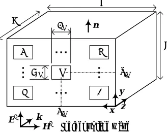
A perfectly-conducting rectangular enclosure of zero thickness with dimensions a×b×c and N rectangular apertures on one side (i.e., the wall located at plane z = 0) is depicted schematically in Figure 1. The periphery surface of the enclosure is denoted as S and the outward-directed unit vector normal to S is denoted as n. The dimensions of the nth (n = 1, 2, …, N) aperture are given
by Ln×Wn and the coordinates of its center point are given
by (xcn, ycn, 0). The cavity is illuminated by a z-directed
plane wave of frequency ω (= 2πf) given as
i = e−jkz
E u (1)
where j is the unit complex number, k ω εµ 2π λ
⎛= = ⎞
⎜ ⎟
⎝ ⎠ is
the surrounding medium wave number in which ε and µ are, respectively, the medium permittivity and permeability and λ is the wavelength, and u is the polarization vector which may be either x-directed x or y-directed y as shown in Figure 1.
N
i 1
j
Wn
Ln
n
xcn
ycn
x y
z
a
b c
Ei
Hi Incident plane wave
n
k
Figure 1: Geometry of the problem.
[ ]
20log intext
SE = − ⎛⎜ ⎞⎟
⎜ ⎟
⎝ ⎠
E
E (2)
where Eint is the electric field at a given point inside the enclosure and Eext is again the electric field at the same point but at the absence of the enclosure.
A. Electric Field Integral Equation and Moment Method Formulation
The incident electric field Ei induces the surface
current Js on the enclosure surface S which, in turn, gives
rise to the scattered electric field Es. Applying the
boundary condition of vanishing tangential electric field on the perfectly conducting cavity surface S, one can find the governing electric field integral equation as follows
(
i s)
0× + =
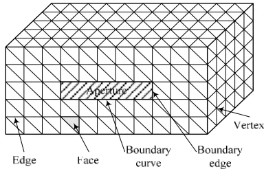
n E E (3) In order to numerically solve the EFIE given in (3) for the surface current distributions, the Galerkin method with the so-called RWG expansion (basis) and test (weighting) functions is utilized as detailed in [21]. In this regard, the enclosure surface is first modeled as a network of adjacent triangular patches, Figure 2. The current distribution is then expanded in a finite series of M expansion functions, fm(r'), as follows
( )
1 M
s m m
m I
=
′ ≈
∑
J f r (4)
where Im are the unknown expansion coefficients to be
determined and r' is the position vector of a point within the basis triangle. In order to obtain the M unknown coefficients, a testing procedure using the same RWG functions is employed at M separate non-boundary edges [21]. This results in an M×M linear system of algebraic equations which can be solved for the unknown coefficients using appropriate solution techniques. Once the current distributions on the enclosure surface are known, the scattered electromagnetic field distributions exterior to the enclosure can be readily determined [21].
Figure 2: Enclosure surface modeled by means of triangular patches.
In the approach described above, the effect of
vanishing fields interior to the enclosure is implicitly taken into account by replacing the enclosure conducting body with the equivalent surface currents (i.e., the surface equivalent theorem). A separate algorithm is therefore needed to determine the field distributions inside the enclosure for the calculation of shielding effectiveness. The algorithm uses the cavity Green’s function to obtain the enclosure interior field distributions from its exterior field distributions.
B. Conventional Modal-Moment Method
In the modal-MoM, fields interior to the enclosure are assumed to be resulted from field distributions on the apertures. These fields, on the other hand, are resulted from the electromagnetic fields incident to the enclosure. In order to expand aperture field distributions using the modal expansion technique it is assumed that: 1) the thickness of the enclosure walls is negligible, 2) the apertures are relatively small compared to the area of the wall in which they are located, and 3) fields diffracted due to the wall edges are negligible. With reference to Figure 1, the electric field on the apertures, Eapt, induced due to
the incident plane wave given by (1) can be expanded as
( ) ( )
( )
1 0 1
1 1 0
, ,
,
Q N P apt
npq npq n p q
Q N P
npq npq n p q
x y V x y
U x y
φ
ψ
= = =
= = =
′ ′ = ′ ′
′ ′ +
∑∑∑
∑∑∑
E x
y
(4)
where x' and y' are coordinates along the apertures, p = 0, 1, …, P and q = 0, 1, …, Q are aperture mode indices, n = 1, 2, …, N is the aperture number, Unpq and Vnpq are the
unknown expansion coefficients to be determined, and
npq
ψ and φnpq are the entire-domain sinusoidal basis
functions given in [9]. Using the equivalence principle, the apertures are replaced by the corresponding magnetic currents, Mapt, as follows
(
,)
(
,)
apt x y′ ′ = × apt x y′ ′
M n E (5) where n is outward directed vector normal to the aperture surface.
An appropriate boundary condition is then required to obtain the unknown aperture current distributions. From the continuity of the tangential component of magnetic field on the apertures, one can write
(
i s)
0 c 0z
z= =
× + = ×
n H H n H (6)
where Hi is the incident magnetic field, Hs is the scattered
magnetic field, and Hc is the magnetic field inside the
enclosure. Again the Galerkin method can be used to solve (7) for the unknown coefficients Unpq and Vnpq as
detailed in [9].
C. Proposed Modal- Moment Method
Solving (7) by using the Galerkin method is computationally inefficient since a large number of modes are to be incorporated in the aperture current distributions and cavity inside fields for an accurate result. This becomes more pronounced as multiple apertures appear on the enclosure surface. In fact, one must take account of coupling among apertures besides the inherit coupling among several modes defined on each aperture, requiring excessive time-consuming numerical integrations. To resolve the aforementioned drawback, we propose a new testing procedure.
As stated earlier, fields outside the enclosure (i.e., z < 0) can be calculated using either the surface electric current distributions on enclosure metallic surface or the surface magnetic current distributions on enclosure apertures surface. From the uniqueness theorem, the two approaches must give the same solutions. As a result, one can use the solutions from one of the two approaches for testing the results obtained from the other approach. The proposed testing procedure is believed to be faster than the conventional procedure where the boundary conditions relating inner and outer magnetic field distributions are used for obtaining the unknown coefficients in (5). This is due to the fact that in the proposed method, there is no need to consider the coupling among apertures which, in turn, reduces the number of time-consuming numerical integrations.
In order to obtain N×P×Q unknown expansion coefficients in the aperture field distributions of (5) denoted by Unpq and Vnpq, fields scattered due to electric
currents on the enclosure metallic surface are calculated at N×P×Q points using the free space Green’s function. These fields are tested against electric fields scattered due to the assumed electric field distributions along the apertures given by (5) which gives the following independent linear systems of equations for Unpq and Vnpq
( ) ( ) ( ) ( ) ( ) ( ) ( ) ( ) ( ) ( ) ( ) ( )
1 1 1 1 1 1 1 1 1 1 1 1
110 110
110
110
s
npq NPQ y
n p q n p q n p q s n p q
npq
npq NPQ y
N P Q N P Q N P Q s N P Q
NPQ
npq NPQ y
A A A U E
U
A A A E
U
A A A E
× × × × × × × × × × × × × × × × × × × × × × × × ⎡ ⎤⎡ ⎤ ⎡ ⎤ ⎢ ⎥⎢ ⎥ ⎢ ⎥ ⎢ ⎥⎢ ⎥ ⎢ ⎥ ⎢ ⎥⎢ ⎥ =⎢ ⎥ ⎢ ⎥⎢ ⎥ ⎢ ⎥ ⎢ ⎥⎢ ⎥ ⎢ ⎥ ⎢ ⎥⎢ ⎥ ⎢ ⎥ ⎣ ⎦ ⎢ ⎥ ⎢ ⎥ ⎣ ⎦ ⎣ ⎦ " " # % # % # # # " " # # % # % # # " " (8) ( ) ( ) ( ) ( ) ( ) ( ) ( ) ( ) ( ) ( ) ( ) ( )
1 1 1 1 1 1 1 1 1 1 1 1
101 101
101
101
s
npq NPQ x
n p q n p q n p q s n p q npq
npq NPQ x
N P Q N P Q N P Q NPQ s N P Q
npq NPQ x
B B B V E
V
B B B E
V
B B B E
× × × × × × × × × × × × × × × × × × × × × × × × ⎡ ⎤⎡ ⎤ ⎡ ⎤ ⎢ ⎥⎢ ⎥ ⎢ ⎥ ⎢ ⎥⎢ ⎥ ⎢ ⎥ ⎢ ⎥⎢ ⎥ =⎢ ⎥ ⎢ ⎥⎢ ⎥ ⎢ ⎥ ⎢ ⎥⎢ ⎥ ⎢ ⎥ ⎢ ⎥⎢ ⎥ ⎢ ⎥ ⎣ ⎦ ⎢ ⎥ ⎢⎣ ⎥⎦ ⎣ ⎦ " " # % # % # # # " " # # % # % # # " " (9)
where s n p q( ) x
E × × and s n p q( )
y
E × × are, respectively, x and y
components of the scattered electric fields due to the electric current distributions on the enclosure metallic surface at the (n×p×q)th observation (test) point in which
n = 1, 2, …, N is the aperture number, p = 0, 1, …, P is
the aperture mode index along x, q = 0, 1, …, Q is the aperture mode index along y, and
2
1 4
x y
z jk x jk y
jk z z
npq npq x y
A e e dk dk
π ∞ ∞ + ′ − − −∞ −∞
= −
∫ ∫
Ψ (10)2
1 4
x y
z jk x jk y
jk z z
npq npq x y
B e e dk dk
π ∞ ∞ + ′ − − −∞ −∞
= −
∫ ∫
Φ (11)where Ψnpq and Φnpq are respectively the spectral
representations of ψnpq and φnpq [9], and
2 2 2
0
z x y
k = k −k −k (12) where k0 is the free space wave number.
As it is clearly seen in (8) and (9), the y component of the electric field is used for the testing procedure of obtaining Unpq and the x component of the electric field is
used for the testing procedure of obtaining Vnpq. This is
due to the fact that the y component of the aperture scattered field is dependent only on Unpq coefficients and
the x component of the aperture scattered field is dependent only on Vnpq coefficients [9].
For observation points very close to the enclosure surface, especially when their distance becomes comparable to the maximum length of RWG edges, the EFIE approach becomes inaccurate. Accordingly field testing points must be far enough from the cavity surface to obtain reasonable predictions for aperture current distributions. Usually the length of each RWG edge must be smaller than λ/8−λ/10, where λ is the minimum operating wavelength [22].
3. NUMERICAL ANALYSIS AND RESULTS
A. Validation against Measurements and Data Available in the Literature
With Reference to Figure 1, a rectangular perfectly conducting enclosure with dimensions a = 30 cm, b = 12 cm, and c = 30 cm is used to check the validity of the proposed method against measurement given in [4] and the conventional modal method of moments [9]. A +y polarized plane-wave traveling along the +z direction characterized by (1) illuminates the cavity and penetrates inside the cavity through an aperture of length L1 = 10 cm
and width W1 = 0.5 cm located centrally in the rectangular
coordinate system at (15 cm, 6 cm, 0 cm) on the enclosure wall.
the aperture and within the enclosure in the regenerated curve of the conventional modal method of moments. A comparison of the results shown in this figure demonstrates the accuracy of the method proposed in this paper.
In order to further validate the proposed method, a comparison has been made with the results of [11] which uses hybrid modal-MoM approach for a two-aperture enclosure with dimensions a = 30 cm, b = 12 cm, and c = 30 cm. With reference to Figure 1 the apertures are located at (7.5 cm, 6 cm, 0 cm) and (22.5 cm, 6 cm, 0 cm) on the wall illuminated by a +y polarized incident plane-wave. The y-component electric field shielding effectiveness at the cavity center point calculated using the method proposed in this paper is shown in Figure 4 for three different aperture dimensions of L1 = L2 = 6 cm,
10 cm, 14 cm and W1 = W2 = 0.5 cm, 2 cm, 10 cm (see
Figure 1). The regenerated results of figure 6 of [11] are also shown in this figure. This figure emphasizes the accuracy of the proposed method for a two-aperture enclosure.
0 200 400 600 800 1000
-40 -20 0 20 40 60 80
Figure 3: Shielding effectiveness versus frequency when calculated at the center of a rectangular metallic enclosure with dimensions 30 cm × 12 cm × 30 cm, containing a rectangular aperture of dimensions 10 cm × 0.5 cm located at the center of the perpendicularly illuminated wall (Figure 3).
0 200 400 600 800 1000
-40 -20 0 20 40 60 80 100
Figure 4: Y-component shielding effectiveness calculated at the center of a rectangular metallic enclosure with dimensions 30 cm × 12 cm × 30 cm, containing two rectangular apertures located at (7.5 cm, 6 cm, 0 cm) and (22.5 cm, 6 cm, 0 cm) on the perpendicularly illuminated wall (Figure 1) for three different aperture dimensions.
B. Multiple-Aperture Enclosures
In practice, shielding enclosures usually contain several apertures. These apertures are incorporated on the surface of the enclosure to serve for various applications, including the ventilation of the enclosure interior.
To demonstrate the computational efficiency of the proposed method in a multiple-aperture application, the electric field shielding effectiveness at the enclosure center point with several apertures is calculated, using the method proposed in this paper and the conventional modal-moment method [9]. With reference to Figure 1, the dimensions of the enclosure are a = 13 cm, b = 12 cm, and c = 30 cm. All apertures are identical and are placed in a vertical column parallel to the y-axis, Figure 5. The two neighboring apertures are separated by the same distance d = 0.5 cm. Also, the dimensions of the nth
aperture are Ln = 10 cm and Wn = 0.5 cm while the
coordinates of its center point are given by (a/2, ycn, 0).
To obtain the results, it is assumed that the number of modes for the enclosure and each of the apertures are, respectively, 2550 and 5.
Figure 5: An array of identical apertures placed in a vertical column parallel to the y-axis on the illuminated wall of the enclosure.
1 2 3 4 5 6 7 8
0 0.2 0.4 0.6 0.8 1
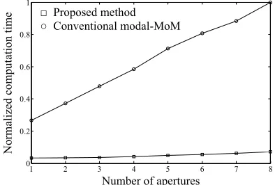
Figure 6: Normalized computation time for calculation of the shielding effectiveness at the center of a rectangular metallic enclosure with dimensions 30 cm × 12 cm × 30 as a function of the number of apertures when using the conventional modal-moment [4] and the method proposed in this paper.
Figure 6 shows the normalized computation time against the number of apertures for the two methods. Notice that all computations are done using the same
Frequency [MHz]
Shi
elding effec
ti
venes
s
[dB]
Proposed method Conventional modal-MoM
UU Measurement [4]
Frequency [MHz]
Sh
ie
ld
in
g ef
fect
iv
en
ess
[
dB
] Proposed method
UU Conventional modal-MoM
6 cm × 0.5 cm
14 cm × 10 cm
10 cm × 2 cm
Number of apertures
No
rm
alized
comp
utation
time
computer. Also, the normalizing factor in all cases is the time taken to compute the shielding effectiveness when the enclosure contains eight apertures and the conventional modal moment method is used. A comparison of the results in Figure 6 shows that the proposed method provides a remarkable faster computation time over the conventional modal-moment method. Also, it is observed that as the number of apertures increases, the conventional modal-moment method becomes prohibitively slow. Instead, the proposed method is almost insensitive to the total number of apertures. This feature reflects the computational burden introduced in the calculation of the aperture current distributions in the conventional modal-moment method. Notice that in the proposed method, this process is replaced with the moment-method solution of the EFIE for metallic surface current distributions whose computational resources exhibit a behavior almost independent of the number of apertures as one can readily infer from the EFIE formulation.
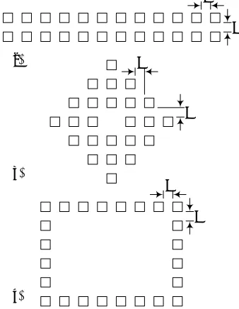
C. Aperture Lay-outs in Multiple-Aperture Enclosures Here, we examine various aperture lay-outs in a multiple-aperture enclosure as encountered in a practical situation. Three distinct lay-outs of 24 rectangular apertures are considered as shown in Figure 7. These are the simple rectangular lay-out, the diamond lay-out, and the strip rectangular lay-out. With reference to Figure 1, the multiple-aperture array is located centrally on the perpendicularly illuminated wall of a metallic enclosure with dimensions a = 30 cm, b = 12 cm, and c = 30 cm. Each aperture has equal length and width Ln = Wn = 0.5
cm (n = 1, 2, …, 24) and the separation distance between two neighboring apertures, d, is the same for all three cases.
Figure 8 shows the shielding effectiveness of the enclosure at its center for the three aperture lay-outs described above for inter-aperture separation distance of d = 0.25 cm when the operating frequency varies from 0 to 1000 MHz. As it is observed in this figure, the diamond lay-out exhibits better shielding effectiveness behavior compared to the two other lay-outs, demonstrating the importance of the apertures lay-out for optimal shielding effectiveness.
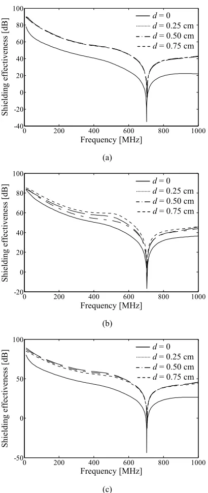
Finally, we study the effects of inter-aperture separation distance for each of the three cases mentioned above. Four different values of d = 0 cm, 0.25 cm, 0.5 cm, and 0.75 cm are examined for the inter-aperture separation distance. The enclosure shielding effectiveness at its center for various values of d are plotted in Figure 9. As clearly seen in this figure, for a simple rectangular lay-out, the shielding effectiveness is almost insensitive to the separation distances studied here except a considerable degradation for d = 0 cm separation. The diamond configuration, on the other hand, exhibits an oscillatory nature of shielding effectiveness around the separation
distance. On the contrary, the strip rectangular lay-out demonstrates a linear behavior of shielding effectiveness around the separation distance. Such observations emphasize the importance of the effects of different aperture lay-outs and effects of separation distance on the shielding effectiveness behavior of metallic enclosures. Unpredictable results given in Figures 8 and 9 confirm that an appropriate design of a practical shielding enclosure to meet desired level of shielding is still a challenging task for an EMC engineer.
d
d
d
d
d
d
(a)
(b)
(c)
Figure 7: Three practical lay-outs for a multiple-aperture array; (a) simple rectangular lay-out, (b) diamond lay-out, and (c) strip rectangular lay-out.
0 200 400 600 800 1000
-20 0 20 40 60 80 100
Figure 8: Shielding effectiveness versus frequency when calculated at the center of a multiple-aperture rectangular metallic enclosure with dimensions 30 cm × 12 cm × 30 cm, containing 24 rectangular 0.5 cm × 0.5 cm apertures of various lay-outs at the center of the perpendicularly illuminated wall and separated by distance d = 0.5 cm.
Frequency [MHz]
Sh
ield
ing
effectiven
ess
[dB]
Simple rectangular Diamond
Strip rectangular Simple rectangular Diamond
0 200 400 600 800 1000 -40
-20 0 20 40 60 80 100
(a)
0 200 400 600 800 1000
-20 0 20 40 60 80 100
(b)
0 200 400 600 800 1000
-50 0 50 100
(c)
Figure 9: Effects of inter-aperture separation distance of various aperture lay-outs on the shielding effectiveness of the multi-aperture metallic enclosure specified in Figure 7 for the frequency range from 0 Hz to 1000 MHz. All apertures are
rectangular with dimensions 0.5 cm × 0.5 cm located at the center of the perpendicularly illuminated wall with separation distance d = 0 cm, 0.25 cm, 0.5 cm, and 0.75 cm; (a) the simple rectangular lay-out, (b) the diamond lay-out, and (c) the strip rectangular lay-out.
4. CONCLUSION
A new hybrid modal-moment method has been proposed to evaluate the shielding effectiveness of a rectangular metallic enclosure with arbitrary number of apertures and arbitrary lay-outs illuminated by an incident plane wave. The method, first, makes use of the frequency domain method of moments (MoM) solution of the governing electric field integral equation for the electric current distributions on the surface of a perfectly conducting enclosure. These current are then used in a separate procedure to obtain magnetic current distributions on apertures. The solution is based on the modal expansion of the fields on the apertures. Since the time-consuming evaluations of the infinite and weekly-damping integrals in the conventional modal technique is replaced with a straightforward and rapid process of evaluating electric currents on metallic surfaces, the proposed method provides significant advantages over the conventional modal-MoM. The validity of the proposed method has been demonstrated by comparing the theoretical and experimental values of electric shielding effectiveness for a rectangular conducting enclosure with single and double aperture illuminated by a plane-wave traveling through a rectangular aperture on the enclosure wall. The method has been used to study various realistic aperture lay-outs in a multiple-aperture metallic enclosure for which the conventional modal-moment method becomes prohibitively slow. It has been shown that the geometrical distributions of apertures in a multiple aperture array can strongly affect the enclosure shielding effectiveness.
5. ACKNOWLEDGMENT
The authors wish to gratefully thank the financial support provided by Iran Telecommunication Research Center (ITRC).
6. REFERENCES
[1] C. R. Paul, Introduction to Electromagnetic Compatibility, New Jersey: Wiley, 2006.
[2] H. A. Mendez, “Shielding theory of enclosures with apertures,” IEEE Trans. Electromagn. Compat., vol. 20, no. 2, pp. 296-305, May 1978.
[3] G. Cerri, R. D. Leo, and V. M. Primiani, “Theoretical and experimental evaluation of the electromagnetic radiation from apertures in shielded enclosures,” IEEE Trans. Electromagn. Compat., vol. 34, no. 4, pp. 423-432, Nov. 1992.
[4] M. P. Robinson, T. M. Benson, C. Christopoulos, J. F. Dawson, M. D. Ganley, A. C. Marvin, S. J. Porter, and D. W. P. Thomas, “Analytical formulation for the shielding effectiveness of
enclosures with apertures,” IEEE Trans. Electromagn. Compat., vol. 40, no. 3, pp. 240-248, Aug. 1998.
[5] W. Wallyn, D. D. Zutter, and E. Laermans, “Fast shielding effectiveness prediction for realistic rectangular enclosures,” IEEE Trans. Electromagn. Compat., vol. 45, no. 4, pp. 639-643, Nov. 2003.
[6] C. F. Bunting, “Shielding effectiveness in a two-dimensional reverberation chamber using finite-element techniques,” IEEE Trans. Electromagn. Compat., vol. 45, no. 3, pp. 548-552, Aug. 2003.
[7] D. M. Hockanson, J. L. Drewniak, T. H. Hubing, and T. P. VanDoren, “Application of finite-difference time-domain method
Frequency [MHz]
Sh
ield
ing
effectiven
ess
[dB]
Sh
ield
in
g effectiv
eness
[dB]
Sh
ield
in
g ef
fect
iv
eness
[
dB]
Frequency [MHz]
Frequency [MHz] d = 0 d = 0.25 cm
d = 0.50 cm
d = 0.75 cm
d = 0 d = 0.25 cm
d = 0.50 cm
d = 0.75 cm
d = 0 d = 0.25 cm
d = 0.50 cm
to radiation from shielded enclosures,” in Proc. IEEE Int. Symp. on Electromagn. Compat., 22-26 Aug., 1994, pp. 83-88.
[8] M. Li, J. Nuebel, J. L. Drewniak, R. E. DuBroff, T. H. Hubing, and T. Van Doren, “EMI from cavity modes of shielding enclosures FDTD modeling and measurement,” IEEE Trans. Electromagn. Compat., vol. 42, no. 1, pp. 29-38, Feb. 2000.
[9] M. D. Deshpande, “Electromagnetic field penetration studies,” NASA/CR-2000-210297, Jun. 2000.
[10] Z. A. Khan, C. F. Bunting, and M. D. Deshpande, “Shielding effectiveness of metallic enclosures at oblique and arbitrary polarizations,” IEEE Trans. Electromagn. Compat., vol. 47, no. 1, pp. 112-122, Feb. 2005.
[11] V. Rajamani, C. F. Bunting, M. D. Deshpande, and Z. A. Khan, “Validation of modal/MoM in shielding effectiveness studies of rectangular enclosures with apertures,” IEEE Trans. Electromagn. Compat., vol 48, no. 2, pp. 348-353, May 2006.
[12] W. Wallyn, D. D. Zutter, and H. Rogier, “Prediction of the shielding and resonant behavior of multisection enclosures based on magnetic current modeling,” IEEE Trans. Electromagn. Compat., vol. 44, no. 1, pp. 130-138, Feb. 2002.
[13] Z. B. Zhao, X. Cui, L. Li, and B. Zhang, “Analysis of the shielding effectiveness of rectangular enclosure of metal structures with apertures above ground plane,”, IEEE Trans. Magnetics, vol. 41, no. 5, pp. 1892-1895, May 2005.
[14] I. Belokour and J. LoVetri, “A 2-D transmission line model for the EM field estimation inside enclosures with apertures,” IEEE Int. Symp. on Electromagn. Compat., vol. 1, 19-23 Aug. 2002, pp. 424-429.
[15] J. Paul, V. Podlozny, and C. Christopoulos, “The use of digital filtering techniques for the simulation of fine features in EMC problems solved in the time domain,” IEEE Trans. Electromagn. Compat., vol. 45, no. 2, pp. 238-244, May 2003.
[16] T. Konefal, J. F. Dawson, A. C. Marvin, M. P. Robinson, and S. J. Porter, “A fast circuit model description of the shielding effectiveness of a box with imperfect gaskets or apertures covered by thin resistive sheet coatings,” IEEE Trans. Electromagn. Compat., vol. 48, no. 1, pp. 134-144, Feb. 2006.
[17] P. Sewell, J. D. Turner, M. P. Robinson, D. W. P. Thomas, T. M. Benson, C. Christopoulos, J. F. Dawson, M. D. Ganley, A. C. Marvin, and S. J. Porter, “Comparison of analytic, numerical and approximate models for shielding effectiveness with measurement,” IEE Proc. Sci. Meas. Tech., vol. 145, no. 2, pp. 61-66, Mar. 1998.
[18] J. M. Jin and J. L. Volakis, “A finite-element-boundary integral formulation for scattering by three-dimensional cavity-backed apertures,” IEEE Trans. Antennas Propagat., vol. 39, no. 1, pp. 97-104, Jan. 1991.
[19] M. S. Sarto, “Hybrid MFIE/FDTD analysis of the shielding effectiveness of a composite enclosure excited by a transient plane wave,” IEEE Trans. Magnetics, vol. 36, no. 4, pp. 946-950, Jul. 2004.
[20] C. Feng and Z. Shen, “A hybrid FD-MoM technique for predicting shielding effectiveness of metallic enclosures with apertures,” IEEE Trans. Electromagn. Compat., vol. 47, no. 3, pp. 456-462, August 2005.
[21] S. M. Rao, D. R. Wilton, and A. W. Glisson, “Electromagnetic scattering by surfaces of arbitrary shape,” IEEE Trans. Antennas Propagat., vol. 30, no. 3, pp. 409-418, May 1982.