AUT J. Elec. Eng., 51(1) (2019) 71-82 DOI: 10.22060/eej.2019.14681.5238
Optimal PMU Placement Considering HVDC Links and Voltage Stability Requirements
M. Dalali, H. Kazemi Karegar*
Faculty of Electrical Engineering, Shahid Beheshti University, Tehran, Iran
ABSTRACT: In wide-area measurement systems, PMUs are the main component measuring real time-synchronized data from different buses. Installation of PMUs at all buses is a primary way to provide full observability of the power network. However, it is not practical in real networks due to the relatively expensive cost of PMUs and other technical limitations. Optimal PMU Placement (OPP) is an optimization problem providing full observability of the power network with a minimum number of PMUs. However, additional goals are often considered in OPP problem. In this paper, OPP problem is solved from voltage stability viewpoints. The presence of VSC-HVDC based resources and decomposition of the power network into intentional islanded parts are selected as two main approaches to improve the voltage stability margin in the power network. Hence, OPP solution is obtained considering both integrated and islanded operation modes of the network with the presence of HVDC links and their voltage stability considerations. Since the location of HVDC could simultaneously affect the network voltage stability and OPP results, the proposed algorithm is designed as a multi stage method to obtain optimal locations for both HVDC link and PMUs. Due to the linear and binary structure of the problem, Binary Integer Linear Programming (BILP) is used to solve the problem. The performance of the proposed OPP problem is investigated on IEEE 14-, 30- and 118-bus test systems considering normal operation and different contingencies consist of Single PMU Failure (SPF) and Single Line Outage (SLO).
Review History: Received: 3 July 2018 Revised: 26 March 2019 Accepted: 1 April 2019 Available Online: 1 April 2019
Keywords:
HVDC islanding observability PMU placement voltage stability
1- Introduction
Nowadays, Wide Area Measurement (WAM) systems play an essential rule in Voltage Stability Assessment (VSA) of modern power systems. Full observability of the power system is the main necessity of WAM systems, which could be obtained by placing a minimum number of PMUs at certain buses. This procedure is called OPP problem [1, 2]. Different methods proposed in the works of literature to solve OPP problem were classified into two main groups: mathematical methods and intelligent approaches. Most of the mathematical methods are based on Integer Linear Programming (ILP) [1-7], and Intelligent approaches consist of GA [8], Tabu search [9], Binary PSO [10], Binary Imperialistic Competition Algorithm (BCIA) [11] and Binary Cuckoo Optimization Algorithm (BCOA) [12].
On the other hand, the installation of HVDC links in power systems is increased due to their special features, such as improvement in voltage and transient stability margins, even for short term and long term instability studies [13]. The presence of HVDC could affect the observability of network buses and changes OPP results [14]. It is also necessary to obtain the voltage and current phasors at both ac sides of HVDC for VSA [15], and produces new constraints in OPP. Although decomposition of the power system into intentional islanded parts could improve the voltage stability of each decomposed island, it reduces the connectivity of network buses and imposes larger number of PMUs on OPP to provide network full observability [16].
In this paper, a multi-stage OPP problem considering HVDC locations and intentional islanding is proposed for VSA. At
the first stage, suitable buses for the connection of HVDC are determined based on their positive effect on the network voltage stability margin. It is assumed that one side of HVDC is connected to a fixed bus such as an offshore wind farm bus and the other side will be connected to network buses one by one. All topologies are ranked based on the value of maximum loading factor obtained by Continuation Power Flow Program (CPFP) and candidate buses, which provides maximum voltage stability improvement will be determined. As each HVDC location creates a new network configuration with different PMU locations, then at the second stage, OPP problem is only solved for candidate configurations determined in the first stage. This procedure has two main benefits: the first one is improving VSA based on the connection of HVDC to network buses and the second one is due to the significant reduction in computational burden, especially for the large scale networks, because OPP problem is only solved for a subset of candidate configurations. The main objective function of the proposed OPP problem is defined as the minimum number of PMUs that maximize the redundancy of the network in interconnected and island conditions. The constraints are full observability of the network and VSA requirements of HVDC. Different contingencies consist of Single PMU Failure (SPF) and Single Line Outage (SLO) which are also considered.
2- VSA in the Presence of HVDC and Its OPP Requirements
To obtain full observability of the power network, each bus should be observable at least one time as direct, indirect or pseudo observable bus [12]. A bus is directly observable if a PMU is installed at that bus. The adjacent bus of a direct observable one is an indirect observable bus. As shown in
Fig. 1, buses 2, 5, and 7 are direct observable buses and buses 1, 3, and 4 are indirect observable ones. The voltage of indirect observable buses can be calculated by voltage and current phasors of their adjacent observable buses as:
(indirect) (direct)
i j ij ij
V =V −Z I (1)
where Vi, Iij and Zij are the voltage phasor of ith bus, the line current phasor and impedance between buses i and j, respectively. The pseudo observable bus does not need a PMU and can be observed by nodal equations. Each pseudo observable bus belongs to a Zero Injection Cluster (ZIC). A ZIC consists of a Zero Injection Bus (ZIB) and all of its adjacent buses. In Fig. 1, bus 1 is a ZIB, because it is only connected to other buses and no loads or generators are connected to it. Hence, buses 1, 2, 3, 4, and 6 make a ZIC. The voltage of bus 6 can be obtained by (2) without any need to install an additional PMU.
1 3 1 6
1 2 1 4
12 13 14 16
0
V V V V
V V V V
Z Z Z Z
− −
− −
+ + + =
(2) The variable V6 is the only unknown parameter in (2) and can be easily calculated by the voltage of direct and indirect observable buses. Therefore, if all buses of a ZIC except one bus are observable, then the unobservable bus will be observable by the pseudo measurement and known as a pseudo observable bus.
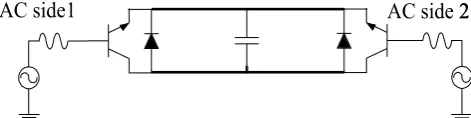
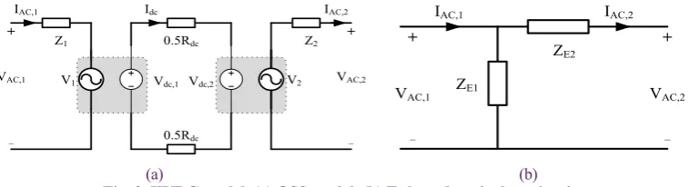
A typical structure of HVDC is shown in Fig. 2. Indirect and pseudo observability approaches are not applicable to HVDC due to its dc characteristics [14]. On the other hand, the Quasi Steady-State (QSS) model of HVDC and its Г shaped equivalent circuit are presented in Fig. 3. It is necessary to obtain equivalent impedances of Г shaped circuit, i.e., ZE1 and ZE2, for its VSA as follows [15]:
,1 1
,1 ,2
= AC ,
E
AC AC
V Z
I −I (3)
,1 ,2
2
,2
= AC AC ,
E
AC
V V
Z
I
−
(4)
where, VAC,1, VAC,2, IAC,1 and IAC,2 are synchronized voltage and current phasors at both ac sides of HVDC. However, ac current phasors IAC,1 and IAC,2 can only be determined, if their connected buses are directly observable; otherwise, only voltage phasors of indirect and pseudo observable buses are known. For example and without loss of generality, it is assumed that HVDC can be connected between two loads or generation buses, such as buses 3 and 6 in Fig. 1. Bus 3 is an indirect observable bus and bus 6 is the pseudo observable bus. KCL for buses 3 and 6 are expressed in (5) and (6),
respectively.
3HVDC 3load 31 37 0,
I +I +I +I = (5)
6HVDC 6load 6gen 61 0.
I +I +I +I = (6) where, I3load, I
6load, I3HVDC and I6HVDC are load currents and ac side currents of HVDC connected to buses 3 and 6, respectively. The parameter I6gen is the injection current of the generator connected to bus 6 and I31, I37 and I61 are currents of lines connected between buses (3,1), (3,7) and (6,1), respectively. At least two parameters in each equation are unknown, which are I3load and I
3HVDC in (5) and I6load, I6HVDC and I6gen in (6). Thus, current phasors of HVDC cannot be determined by using indirect and pseudo measurements and it is necessary to install two PMUs at both ac sides of HVDC to provide observability as direct measurement.
Hence, the presence of HVDC changes PMU locations. For example, new locations of PMUs in Fig. 1 are buses 3, 5, and 6. Thus, the above buses are direct observable ones, buses 1, 4, and 7 are indirect observable ones and bus 2 is the network pseudo observable bus. Now, in addition to full voltage observability of the network, the current phasors of HVDC at both ac sides are measured that is sufficient for VSA requirements of the network. In special cases, if one side of HVDC is connected to a ZIB, then installation of PMU at that bus could be omitted. For example, suppose that one side of HVDC is connected to bus 1 (ZIB). Hence, KCL for this bus will be:
1HVDC 12 13 14 16 0.
I +I +I +I +I = (7)
Since the voltage of bus 1 and its adjacent buses are known, their line currents can be calculated. In this case, I1HVDC will be obtained by using (7) and it is not necessary to install a PMU at bus 1. As a result, the connection of HVDC to different buses produces different constraints in OPP problem. Considering the mentioned notes, each bus may belong to one of the three sets: ZIBs set, ZICs set (adjacent buses of ZIBs) and simple buses set. A simple bus does not belong to a ZIB or ZIC set and the pseudo observability approach is not applicable to it. Some notes should be considered in OPP problem for the connection of HVDC to each group of buses.
ZIBs set: If each side of HVDC is connected to a ZIB, it exchanges electrical power with HVDC. Thus, it converts into a simple bus and its ZIC is eliminated from OPP. Hence, observability as a pseudo measurement is not applicable to all buses of its cluster. Also, the installation of PMU at this ZIB is not necessary for VSA.
ZICs and simple buses sets: If each side of HVDC is connected to other buses of the network, such as ZIC sets or simple buses, then PMU installation at its corresponding bus is necessary and this bus is observable by direct measurement. If the bus belongs to a ZIC set, it is better to remove this bus from its
AC side 22 AC side 1
Fig. 2. Structure of HVDC transmission line.
1 2
3 4
5
6
7 PMU
PMU
PMU
corresponding cluster to increase the observability chance of other ZIC buses by pseudo measurement. Consequently, the full observability can be obtained by using fewer PMU numbers.
3- Structure of the Proposed Method
In this section, the proposed objective function and the required constraints are developed in accordance with BILP. Also, CPFP based algorithm used for the ranking of network buses for the connection of HVDC is illustrated.
3- 1- Formulation of the Proposed BILP
The OPP objective function consists of minimizing the number of PMUs and maximizing the number of times that network buses are observable. These objective functions are stated in (8) and (9), in which function F1 minimizes the number of installed PMUs and function F2 maximizes the redundancy of buses
1 ( )
1
min n i ,
i
F x
=
= ∑ (8)
2 ( )
1 1 max n i ,
i
F O
n =
= ∑ (9)
where, x(i) is a binary decision variable to show that a PMU is installed at bus i, x(i)=1, or not, x(i)=0. The variable O(i) is the number of times that the bus i is observable by direct, indirect and pseudo measurements. The parameter n is the number of network buses. To solve the above functions simultaneously, both objective functions F1 and F2 are combined together as an aggregate objective function F in (10).
( ) ( )
1 1
( ) 1
min ,
(max( ) 1)
n n
i all PMU i
i i
i
F x O
n O
= =
=∑ − ∑
+ (10)
where, O(i)all PMU is the maximum number of times that the bus i is observable when all network buses are equipped with PMUs. The effect of redundancy in (10) always remains lower than one by the usage of this factor (to obtain relative observability). This factor guarantees that function F1 is the main component of the objective function F and its value is dominated in the optimization problem [12, 16]. It means that a solution with less number of PMUs is preferred to one with higher redundancy.
In addition, some sets of constraints should be satisfied in OPP to maintain the network full observability and also provide VSA requirements. First of all, each bus of the network should be observable at least one time. The number of times that bus i is observable will be calculated by fi,1and fi,2. The function fi,1is used for direct and indirect observability and function fi,2 stands for pseudo observability.
,1 ( , ) ( )
1 ,
n
i i j j
j
f a x
=
= ∑ (11)
,2 ( , ( )) ( , ( ))
1 ,
m p
i i ZIB k i ZIB k k
f a x
=
= ∑ (12)
where, m is the number of ZICs in the network. The variable ZIB(k) denotes to kth ZIB of the network. Matrices [a
(i,j)] and [xp
(i,ZIB(k))] are the network connectivity matrix and an auxiliary binary matrix to determine pseudo observable buses, respectively, and are defined as:
( , )
1 line - connects buses and ,
0 otherwise
i j
i j or i j i j
a = =
(13)
( , ( )) 1 is a pseudo unobservable in .
0 otherwise
th p
i ZIB k bus i k ZIC
x =
(14)
The bus observability function fi is composed of fi,1and fi,2 and is defined for each bus (i) as:
,1 ,2 1.
i i i
f =f +f ≥ (15)
At most one bus in each ZIC could be observable as the pseudo observable bus. This constraint is considered as:
( , ( )) ( , ( ))
1 1, 1: .
n p
i ZIB k i ZIB k
i∑=a x ≤ k = m (16)
Installation of PMUs at both sides of HVDC is necessary for VSA requirements. If each side of HVDC is connected to a simple bus or an adjacent bus of a ZIB such as bus h, an equality constraint should be defined as follows:
( ) ( )
1 and bus h is not a . otherwise
i i
if i h ZIB
x = x =
(17)
This constraint is not necessary when HVDC is connected to a ZIB. In addition, the cluster of ZIB connected to one ac side of HVDC will be eliminated from OPP. In such a condition, this ZIB and all of its adjacent buses are not observable by pseudo measurement and some modifications should be considered in OPP. Assume that bus h is a ZIB connected to one side of HVDC and bus i belongs to its cluster. Then, modifications are considered as follows:
( ) ( , ( )) 0, , p
k i ZIB k
x = ZIB =h (18)
1
( )
,2 ( , ( )) ( , ( ))
1 , .
m p
k i i ZIB k i ZIB k
k
f −a x ZIB h
=
= ∑ ≠ (19)
In accordance with (18) and (19), bus i is not observable by a pseudo measurement in kth cluster and it could be observable as a pseudo observable bus when it is a member of other ZICs. Moreover, if each side of HVDC is connected to other buses of a ZIC (ZICs set), e.g. bus h, the observability function related to that bus is satisfied only by its own PMU (fh,1≥1). Thus, it is not necessary for bus h to be observable by pseudo
Z1 + VAC,1 _ + VAC,2 _
IAC,1 Idc
V1
0.5Rdc
0.5Rdc
Vdc,1 Vdc,2 V2
Z2 IAC,2 ZE2 ZE1 + VAC,1 _ + VAC,2 _
IAC,1 IAC,2
(a) (b)
measurement and the function fh,2 could be considered equal to zero. The binary variables related to this bus in all ZICs are set to zero as follows:
( , ( )) 0, 1: . p
h ZIB k
x = k = m (20)
It is possible for HVDC bus to be a ZIB in one cluster and connected to one or more ZIBs in other clusters. In such a condition, both corrective actions in OPP constraints, i.e. (18) - (20), are considered, simultaneously.
3- 2- Modification of the Proposed OPP During Contingencies In this section, the effect of single PMU failure and single line outage on OPP problem is studied and the required constraints are modified. Failure of each PMU affects the direct observability for its own bus and indirect observability for its adjacent buses. Assumed that PMU installed at bus i or a PMU installed at one of its adjacent buses fails. To consider this problem, it is suggested to remove the connection between bus i and one of its adjacent buses such as bus j, i.e., a(i,j)=0, then rewrite its observability function, accordingly. This procedure is continued for all of its adjacent buses to cancel all indirect measurements possible for bus i. Finally, the value of a(i,i) is considered to be zero to cancel its direct measurement. Therefore, the first term of the observability function for bus i (fi,1) is converted into multiple functions as each one is defined by resetting any of the unit value array in ith row of the connectivity matrix to zero. Hence, the influence of the effective PMU failure on the observability of the intended bus could be considered in one of the defined constraints. The number of constraints for the bus i is equal to the number of its adjacent buses plus one or O(i)allPMU. Therefore, fi,1 should be modified to consider the effect of PMU failure at each bus such as h as follows:
( )
,1_ ( , ) ( )
1 , ( 1: ),
n PMU allPMU
h i
i t i j j j
f a x for t O
=
= ∑ = (21)
where, [a(i,j)PMUh] is the connectivity matrix considering PMU failure at an adjacent bus of bus i, e.g., bus h, and is defined as:
( , )
( , ) 0 ,
bus and its adjacent buses. PMUh i j
i j
a j h
a j h h i ≠ = = ∈ (22)
The pseudo measurement is not affected by PMU failures. Its variables (xp) are not changed and are repeated in all of the modified constraints, directly. Thus, the bus observability function (fi) for each bus is repeated O(i)all PMU times by setting one of its direct or indirect variables in the connectivity matrix equal to zero.
,1_1
,2
,1_ ( )
1. i
i i
allPMU i O i
f f f f
= + ≥ (23)
Line outage influences on the network observability as indirect and pseudo measurements. To consider this contingency, any bus of the network such as bus i, should always remain observable when all of its incident lines are removed at one time. Thus, the connectivity matrix [a(i,j)] should be rearranged for the bus i by setting the value of one of its adjacent buses, such as h, to zero. This procedure is repeated for all incident
lines, which is equal to O(i)allPMU-1. It should be noted that the observability as a pseudo measurement is also affected by line outages. Therefore, both parts of the observability function (i.e., fi,1 and fi,2) are repeated O(i)all PMU-1 times and new relations are obtained as:
( )
( )
,1_ ( , ) ( )
1
( , )
,2 _ ( , ( )) ( , ( ))
1
,1_1 ,2 _1
,1_ ( ) 1 ,2 _ ( ) 1
, 1: 1,
,
1,
allPMU i
n line i h
i t i j j
j
m line i h p
i t i ZIB k i ZIB k
k
i i
i
allPMU allPMU
i Oi i Oi
for t O
f a x
f a x
f f f f f − = = − − = − = ∑ = ∑ + = ≥ + (24)
where, [a(i,j)line(i-h)] is the connectivity matrix considering the line outage between bus i and one of its adjacent buses like h and it is defined as:
( , ) ( , )
( , ) 0 ,
adjacent buses of bus i. i j
line i h i j
a j h
a j h h ≠ = = ∈ (25)
In accordance with (16), each ZIC has at most one pseudo observable bus. This constraint should also be modified to consider the outage of all branches used to connect each ZIB to its adjacent buses. Similar to the observability function, line outage between kth ZIB and its adjacent buses, such as bus
h, are considered one by one and (16) is repeated by setting its corresponding array in the connectivity matrix equal to zero.
( , ( ))
( , ( )) ( , ( ))
1 1, 1: .
n line h ZIB k p i ZIB k i ZIB k
i∑=a x ≤ for k = m (26)
The proposed objective function and constraints are defined for the interconnected condition. However, the island condition should also be considered in OPP objective function and constraints. First, the connectivity matrix in the island condition [a(i,j)island] is defined as [16]:
( , ) ( , )
0 ( ) is opened for islanding . otherwise
i j island
i j
line i j
a = a −
(27)
All constraints should be repeated considering the connectivity matrix in island condition and solving both interconnected and island constraints, simultaneously. In addition, the objective function should be modified to consider both conditions [16]. Therefore, it is necessary to determine the redundancy obtained in interconnected and island conditions, separately and use them in the objective function to obtain the solution. In this paper, the redundancy of network buses is considered in interconnected and island conditions using weighting factors ω and 1-ω, respectively. Since power networks are normally utilized in interconnected mode, it is better to assign a greater weight for its redundancy in the objective function. Hence, the value of ω is considered 0.7 in the aggregated objective function as follows [16]:
( ) ( ) ( )
1 1
( ) 1
min ( (1 ) ),
(max( ) 1)
n n island
i allPMU i i
i i
i
F x O O
n O ω ω
= =
=∑ − ∑ + −
+ (28)
3- 3- Determination of Suitable Buses for HVDC Connection Considering VSA
In the last subsections, solving OPP problem considering different locations for connection of HVDC is explained. However, it is not possible to connect HVDC to all buses of power networks, due to technical and economic limitations. In this paper, the influence of HVDC on the network voltage stability is considered as the main criterion to select the structure and location of HVDC.
VSC-HVDC could provide independent active and reactive power outputs due to the fast control on the magnitude and phase angle of its ac side voltages [15, 17]. Thus, they could be used to improve the voltage stability margin of the power network. This technology is adopted in this paper for the connection of the wind farm to the main network.
However, the location of HVDC could affect significantly the amount of voltage stability improvement. If HVDC is connected in the proximity of the load center or critical buses (buses initialize instability in power networks), they would better support the network, especially in abnormal conditions [17]. Thus, it is better to determine the best buses for the connection of HVDC considering its positive effect on the network voltage stability margin. Hence, a candidate subset of buses could be determined for the connection of HVDC and then OPP problem is only solved for suitable structures. Since OPP problem should be solved for each structure, separately, this procedure could also reduce solving numbers of OPP problem.
CPFP is a powerful algorithm to determine collapse point and voltage stability margin of ac/dc power networks. This algorithm consists of two estimators and corrector procedures to obtain accurate results, especially in the proximity of collapse point, where conventional power flow program diverges [18, 19]. In this algorithm, active and reactive powers at selected loads or all load buses are increased gradually until the system reaches the collapse point. To obtain power loads at any iteration, loading factor (λi) is multiplied by the initial active (Pi,0) and reactive powers (Qi,0) of each load bus (i) as follows:
0
0
( ) ( ) , ( ) ( ) ,
i i i
i i i
P k k P
Q k k Q
λ λ
= ×
= × (29)
where, Pi(k) and Qi(k) are active and reactive powers of ith load bus at iteration k. In this paper, all loads are increased uniformly and a global loading factor (λ) is used for all loads. Collapse point occurs at maximum loading factor (λmax) which is the output of CPFP. The greater value of maximum loading factor implies that the studied network is more stable and has a better voltage stability margin. Maximum loading factor should be measured for interconnected and island conditions, separately. Then, a unique value could be obtained similar to the combination of relative observability functions in (28) as follows:
int
=0.7 +0.3 ,
tot isd
λ λ λ (30)
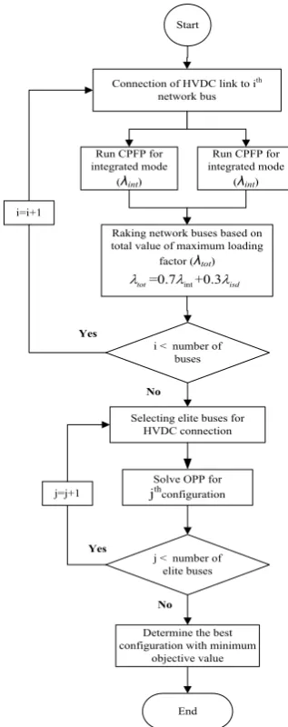
where, λint, λisd and λtot are maximum loading factors for interconnected, island, and both island and interconnected conditions, respectively. The different stages of the proposed OPP are shown in Fig 4.
4- Test Results
The proposed OPP structure is tested on IEEE 14-, 30- and 118-bus test systems. Detailed specifications of test systems and their island parts are presented in [4]. One side of HVDC is connected to the offshore wind farm collector bus and the other side is connected to candidate buses of the network. The obtained results are compared and confirmed by exhaustive search ones for IEEE 14-bus test system.
To obtain candidate configurations, an average model of VSC-HVDC is simulated in DIgSILENT software and it is connected to network buses one by one. For each configuration, the maximum loading factor for interconnected and island conditions is obtained by CPFP coded in DIgSILENT environment. The suitable locations for the connection of HVDC are determined based on the value of their maximum loading factor. Then, OPP is only solved by bintprog solver in Matlab software for candidate configurations.
All simulations are done by a 2 GHz processor with 2 GB of RAM. The average CPU run time for IEEE 14-, 30- and 118-bus test systems is about 0.07, 0.12 and 0.15 s, respectively. In 14 and 30-bus test systems, simulated VSC-HVDC consists of two 40 MW, ±150/380 kV converters providing ±20MVar reactive power support, 160 μF dc capacitor bank,
Start
Connection of HVDC link to ith network bus
End
Raking network buses based on total value of maximum loading
factor (λtot)
Run CPFP for integrated mode
(λint)
int
=0.7 +0.3
tot isd
λ λ λ
Selecting elite buses for HVDC connection
Solve OPP for
jthconfiguration
j < number of elite buses
Determine the best configuration with minimum
objective value
No Yes
Run CPFP for integrated mode
(λint)
i < number of buses
j=j+1 i=i+1
Yes
No
35 mH commutating reactor and 100 km XPLE dc cables. In the 118-bus test system, the active and reactive powers of converters are 120 MW and ±90MVar, respectively. Additional specifications and the control strategy of HVDC converters are presented in [15, 17].
4- 1- IEEE 14-Bus Test System
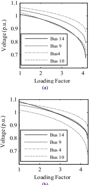
The maximum loading factors for the interconnected, island, and aggregate conditions are presented in Table 1. If HVDC is not connected to the network, bus 14 is the critical bus and initiates voltage instability. Therefore, it is better to connect HVDC to this bus. In accordance with the table results, improvement of maximum loading factor is also more visible when HVDC is connected to bus 14. Moreover, it seems that buses 9 and 10 are also suitable buses for HVDC connection. The voltage profile at some critical buses in the interconnected condition is depicted in Fig. 5. Bus 14 has the worst voltage profile before the connection of HVDC and its characteristic is improved significantly after HVDC is connected to it.
4- 1- 1- Normal Operation
OPP results for normal operation are presented in Table 2. The results are classified into interconnected and both interconnected and island conditions. In both cases, the full observability is obtained with the minimum objective value when no HVDC is connected to the network. Also, the connection of HVDC to buses 2, 6 and 9 in interconnected condition and buses 4, 5, 6, and 9 in both interconnected and island conditions provide minimum objective value. Among these buses, bus 9 can better improve the voltage stability margin. Thus, it is recommended for the connection of HVDC.
4- 1- 2- Single Failure of PMUs
OPP results for single PMU failure are presented in Table 3. In HVDC connected configurations, it is assumed that PMU installed at HVDC bus never fails to obtain its voltage and current phasors for VSA. Thus, the number of constraints in Table 1. Maximum loading factors for IEEE 14-bus test system
DC line bus
no Int (λint) Isd (λisd) Agg (λtot)
No. HVDC 4.117 2.620 3.668
1 4.117 2.620 3.668
2 4.126 2.620 3.674
3 4.160 2.635 3.703
4 4.229 2.737 3.781
5 4.210 2.620 3.733
6 4.221 2.620 3.741
8 4.302 2.859 3.869
9 4.365 2.892 3.923
10 4.365 2.899 3.925
11 4.335 2.895 3.903
12 4.312 2.895 3.887
13 4.324 2.895 3.895
14 4.394 3.043 3.989
1 2 3 4
0.7 0.8 0.9 1 1.1
Loading Factor
V
ol
ta
ge
(p
.u
.)
Bus 14 Bus 9 Bus4 Bus 10
(a)
1 2 3 4
0.7 0.8 0.9 1 1.1
Loading Factor
V
ol
ta
ge
(p
.u
.)
Bus 14 Bus 9 Bus 4 Bus 10
(b)
Fig. 5. Voltage profile at some critical buses in interconnected mode, (a) No HVDC connection, (b) Connection of HVDC to
the bus 14
Table 2. OPP results in IEEE 14-bus test system for normal operation.
DC line bus no
Interconnected net-work
Interconnected and intentional islanded
network PMU
locations Objective value locationsPMU Objective value
Non 2,6,9 2.8469 4-6,9 3.7949
1 1,4,6,9 3.8061 1,4,6,9 3.8122
2 2,6,9 2.8469 2,5,6,9 3.8082
3 3,5,6,9 3.8163 3,5,6,9 3.8224
4 4-6,9 3.7857 4-6,9 3.7949
5 4-6,9 3.7857 4-6,9 3.7949
6 2,6,9 2.8469 4-6,9 3.7949
7 2,6,7,9 3.8061 4-7,9 4.7541
8 2,6,8,9 3.8265 4-6,8,9 4.7745
9 2,6,9 2.8469 4-6,9 3.7949
10 2,4,10,13 3.8163 4-6,9,10 4.7673
11 2,4,11,13 3.8163 4-6,9,11 4.7673
12 2,6,9,12 3.8163 4-6,9,12 4.7643
13 2,6,9,13 3.8061 4-6,9,13 4.7571
HVDC connected cases will be reduced and it is possible to solve OPP with a lower number of PMUs. The connection of HVDC to bus 2 in interconnected condition and to buses 1, 4, 5, 6, and 9 in both interconnected and island conditions creates this condition and requires a lower number of PMUs with respect to no HVDC connected networks. Bus 9 should still be selected for both cases if the network VSA requirement is also considered and bus 10 is only suitable for interconnected condition.
4- 1- 3- Single Line Outage
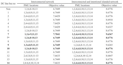
OPP results for the single line outage are shown in Table 4. Bus 7 is a ZIB of the network and it does not need a PMU when it is connected to HVDC. The results of this bus during normal operation and single PMU failure are not different with and without considering this assumption. However, this assumption could influence OPP results in the single line outage study. The obtained results considering this assumption are shown in 7* which describe that omitting PMU will be conducted to the best results. However, the installation of PMU at this bus leads to the worst results as shown in 7. Bus Table 3. OPP results in IEEE 14-bus test system for single PMU failure
DC line bus no Interconnected network Interconnected and intentional islanded network
PMU locations Objective value PMU locations Objective value
Non 2,4-6,9,10,13 6.6633 1,2,4-6,9-11,13,14 9.6020
1 1,2,4,6,9,11,13 6.6837 1,2,4,6, 9-11,13,14 8.6469
2 2,4,6,9,11,13 5.7143 1,2,4-6,9-11,13,14 9.6020
3 2-6,9,10,13 7.6327 1,3-6,9-11,13,14 9.6163
4 2,4-6,9,10,13 6.6633 1,4-6,9-11,13,14 8.6469
5 2,4-6,9,11,13 6.6633 2,4-6,9-11,13,14 8.6296
6 2,4-6,9,10,13 6.6633 1,2,4-6,9,10,14 7.6673
7 2,4-7,9,10,13 7.6224 1,2,4-7,9-11,13,14 10.561
8 2,4-6,8-10,13 7.6429 1,2,4-6,8-11,13,14 10.582
9 2,4-6,9,10,13 6.6633 1,2,4-6,9,11,13 7.6571
10 2,4-6,9,10,13 6.6633 1,2,4-6,9-11,13,14 9.6020
11 2,4-6,9,11,13 6.6633 1,2,4-6,9-11,13,14 9.6020
12 2,4-6,9,11-13 7.6327 1,2,4-6,9-12,14 9.6092
13 2,4-6,9,10,13 6.6633 1,2,4-6,9-11,13,14 9.6020
14 2,4-6,9,11,13,14 7.6327 1,2,4-6,9-11,13,14 9.6020
Table 4. OPP results in IEEE 14-bus test system for single line outage
DC line bus no Interconnected network Interconnected and intentional islanded network
PMU locations Objective value PMU locations Objective value
Non 1,3,6,8-10,13 6.7449 1,2,4,6,8,10,11,13,14 8.6776
1 1,3,6,8,9,11,13 6.7449 1,2,4,6,8,10,11,13,14 8.6776
2 2,4-6,8,9,11,13 7.6429 1,2,4,6,8,10,11,13,14 8.6776
3 1,3,6,8,9,11,13 6.7449 1,3,4,6,8,10,11,13,14 8.6918
4 2,4-6,8,9,11,13 7.6429 1,2,4,6,8,10,11,13,14 8.6776
5 2,4-6,8,9,11,13 7.6429 1,2,4-6,8,10,11,13,14 9.6327
6 1,3,6,8-10,13 6.7449 1,2,4,6,8,10,11,13,14 8.6776
7 1,3,6-9,11,13 7.7041 1,2,4,6-8,10,11,13,14 9.6367
7* 1,3,6,8-10,13 6.7449 1,2,4,6,8,10,11,13,14 8.6776
8 1,3,6,8,9,11,13 6.7449 1,2,4,6,8,10,11,13,14 8.6776
9 1,3,6,8,9,11,13 6.7449 1,2,4,6,8-11,13,14 9.6265
10 1,3,6,8-10,13 6.7449 1,2,4,6,8,10,11,13,14 8.6776
11 1,3,6,8,9,11,13 6.7449 1,2,4,6,8,10,11,13,14 8.6776
12 2,4,5,8,9,11-13 7.6633 1,2,4,6,8,10-12,14 8.6847
13 1,3,6,8,9,11,13 6.7449 1,2,4,6,8,10,11,13,14 8.6776
10 is the only bus in both cases, which provides the best result for OPP and meets VSA requirements, simultaneously. In addition, buses 9 and 14 are only suitable for interconnected condition and both interconnected and island conditions, respectively.
4- 1- 4- Sensitivity Analysis
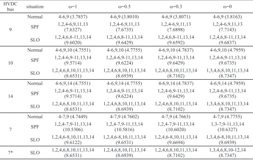
In this paper, the value of the weighting factor ω in OPP objective function is considered 0.7 to promote the influence of the redundancy in the interconnected condition with respect to the island one. However, a sensitivity analysis, considering different values of the weighting factor, is also presented in this section. The results of candidate structures in normal operation, single PMU failure, and single line outage studies are shown in Table 5. Since the number of PMUs is the most influencing parameter in the objective function, the results of each configuration are obtained with the same number of PMUs. However, any value of the weighting factor causes different objective value considering the difference of the measurement redundancy between interconnected and island conditions. In special cases, PMU arrangement varies for
ω=0 in the single line outage study when HVDC is connected to buses 7, 10, and 14, respectively.
4- 2- IEEE 30-Bus Test System
The best buses of IEEE 30-bus test system for the connection of HVDC and their corresponding maximum loading factors for the interconnected, island, and both conditions are presented in Table 6. Bus 30 is the critical bus of the network. Hence, the connection of HVDC to this bus provides maximum improvement in the network voltage stability
margin. In addition, the connection of HVDC to buses 25 to 29 is also recommended. OPP results for candidate structures in normal operation are presented in Table 7. Similar to IEEE 14-bus test system, the best results are obtained when no HVDC is connected to the network buses. The connection of HVDC to buses 2, 4, 10, 15, 18-20, 27, 27*, 29 and 30 for interconnected condition and buses 1, 6*, 7, 10, 12, 16, 19, 22*, 24, 27, 27* and 28* for both interconnected and island conditions could cause the best results. However, each one has its specific locations for installation of PMUs. Also, an improvement is observed in OPP results when the necessity of PMU installation at HVDC connected ZIBs is not considered (“*” superscript results in the table). If the influence of HVDC on the network voltage stability is considered, the results are restricted to buses 27, 27*, 29 and 30 for interconnected conditionand buses 27, 27*and 28*for both interconnected and island conditions, respectively.
The value of the objective function for single event contingencies is shown in Fig. 6. In the interconnected condition, the installation of HVDC at bus 12 for single PMU failure and at buses 2, 3, 7, 9-13, 15-17, 19, 24-26, 28-30 for single line outage have the best results. Their corresponding objective values are 13.8074 and 12.8185, respectively. When the influence of HVDC location on VSA is considered, the best buses are modified as buses 27, 29 and 30 for single PMU failure and buses 26 and 28-30 for single line outage, respectively. Therefore, bus 30 is the best bus for the connection of HVDC in the interconnected condition. The objective function values for this bus are equal to 6.8667 and 13.8074 for normal operation and single event contingencies, respectively. In both interconnected and island conditions, the Table 5. OPP results in IEEE 14-bus test system considering different values of weighting factors
HVDC
bus situation ω=1 ω=0.5 ω=0.3 ω=0
9
Normal 4-6,9 (3.7857) 4-6,9 (3.8010) 4-6,9 (3.8071) 4-6,9 (3.8163)
SPF 1,2,4-6,9,11,13 (7.6327) 1,2,4-6,9,11,13 (7.6735) 1,2,4-6,9,11,13 (7.6898) 1,2,4-6,9,11,13 (7.7143)
SLO 1,2,4,6,8-11,13,14 (9.6020) 1,2,4,6,8-11,13,14 (9.6429) 1,2,4,6,8-11,13,14 (9.6592) 1,2,4,6,8-11,13,14 (9.6837)
10
Normal 4-6,9,10 (4.7551) 4-6,9,10 (4.7755) 4-6,9,10 (4.7837) 4-6,9,10 (4.7959)
SPF 1,2,4-6,9-11,13,14 (9.5714) 1,2,4-6,9-11,13,14 (9.6224) 1,2,4-6,9-11,13,14 (9.6429) 1,2,4-6,9-11,13,14 (9.6735)
SLO 1,2,4,6,8,10,11,13,14 (8.6531) 1,2,4,6,8,10,11,13,14 (8.6939) 1,2,4,6,8,10,11,13,14 (8.7102) 1,3,4,6,8,10,11,13,14 (8.7347)
14
Normal 4-6,9,14 (4.7551) 4-6,9,14 (4.7755) 4-6,9,14 (4.7837) 4-6,9,14 (4.7959)
SPF 1,2,4-6,9-11,13,14 (9.5714) 1,2,4-6,9-11,13,14 (9.6224) 1,2,4-6,9-11,13,14 (9.6429) 1,2,4-6,9-11,13,14 (9.6735)
SLO 1,2,4,6,8,10,11,13,14 (8.6531) 1,2,4,6,8,10,11,13,14 (8.6939) 1,2,4,6,8,10,11,13,14 (8.7102) 1,3,4,6,8,10,11,13,14 (8.7347)
7
Normal 4-7,9 (4.7449) 4-7,9 (4.7602) 4-7,9 (4.7663) 4-7,9 (4.7755)
SPF 1,2,4-7,9-11,13,14 (10.5306) 1,2,4-7,9-11,13,14 (10.5816) 1,2,4-7,9-11,13,14 (10.6020) 1,3-7,9-11,13,14 (10.6327)
SLO 1,2,4,6-8,10,11,13,14 (9.6122) 1,2,4,6-8,10,11,13,14 (9.6531) 1,2,4,6-8,10,11,13,14 (9.6694) 1,3,4,6-8,10,11,13,14 (9.6939)
installation of HVDC at bus 27 for single PMU failure and at buses 1, 4-6, 9, 11-13, 15, 17-21, 24-27, 29 and 30 for single line outage provides the best results. Their corresponding objective values are 16.7641 and 15.7867, respectively. Again, considering the influence of HVDC location on the voltage stability improvement restricts the obtained results as bus 27 is adopted for single PMU failure and buses 25-27, 29 and 30 are selected for single line outage. Thus, no change is observed in OPP results for these studies.
4- 3- IEEE 118-Bus Test System
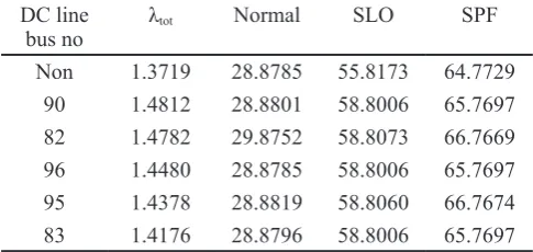
In this section, the performance of the proposed algorithm is evaluated on IEEE 118-bus test system. The value of the loading factor in candidate configurations with their OPP objective function values in normal operation, single line outage and single PMU failure studies are presented in Table 8. The connection of HVDC to buses 90 and 96
Table 6. Maximum loading factors for IEEE 30-bus test system.
DC line bus no Int (λint) Isd (λisd) Agg (λtot)
Non 2.993 1.631 2.584
30 3.606 1.738 3.046
29 3.549 1.728 3.003
27 3.371 1.736 2.881
28 3.371 1.733 2.879
25 3.338 1.726 2.854
26 3.338 1.723 2.853
Table 7. OPP results in IEEE 30-bus test system for normal operation.
DC line bus no Interconnected network Interconnected and intentional islanded network
PMU locations Objective value PMU locations Objective value
Non 2,4,10,12,15,18,27 6.8667 1,7,10,12,16,19,24,27 7.8785
25 2,4,10,12,15,20,25,27 7.8519
1,7,10,12,16,19,24,25,27 8.8648
25* 2,4,10,12,15,18,25,27 7.8519
26 2,4,10,12,15,18,26,27 7.8593 1,7,10,12,16,19,24,26,27 8.8711
27 2,4,10,12,15,20,27 6.8667 1,7,10,12,16,19,24,27 7.8785
27* 2,4,10,12,15,18,27 6.8667
28 2,4,10,12,15,20,27,28 7.8519 1,7,10,12,16,19,24,27,28 8.8637
28* 1,5,10,12,15,18,27 6.8815 1,7,10,12,16,19,24,27 7.8785
29 2,4,10,12,18,24,29 6.8667 1,7,10,12,16,19,24,29 7.8859
30 2,4,10,12,18,24,30 6.8667 1,7,10,12,16,19,24,30 7.8859
1 2 0
5 10
15 20
25 30 0
5 10 15
HVDC Location
G
o
al V
alu
e
Line PMU
(a)
1 2 0
5 10
15 20
25 30 0
5 10 15
HVDC Location
Go
al
Va
lu
e
Line PMU
(b)
Fig. 6. OPP results considering single event contingencies, (a) Interconnected condition, (b) Both interconnected and island
conditions. Table 8. Best configurations with the highest loading factors
and their OPP results for IEEE 118-bus test system. DC line
bus no λtot Normal SLO SPF
Non 1.3719 28.8785 55.8173 64.7729
90 1.4812 28.8801 58.8006 65.7697
82 1.4782 29.8752 58.8073 66.7669
96 1.4480 28.8785 58.8006 65.7697
95 1.4378 28.8819 58.8060 66.7674
provides the best OPP results and the highest loading factors, simultaneously. The location of PMUs for the connection of HVDC to bus 90 is also presented in Table 9. Since bus 90 is a simple bus of the network, PMU installation at this bus is necessary for all studies of this configuration.
4- 4- Comparison with Other Methods
In this section, the performance of the proposed algorithm is compared with BILP [3], BCIA [11] and BCOA [12] in two large-scale networks, e.g. IEEE 118-bus test system and 2383-bus polish network [3], in normal operation. The results of all algorithms, including PMU numbers, the sum of network buses observability, and the convergence time are presented in Table 10. The proposed algorithm provides the best results considering both the network buses observability and the convergence time aspects with the same number of PMUs.
5- Conclusion
In this paper, OPP problem considering voltage stability requirements of HVDC and operation in both interconnected and island conditions was proposed. The influence of HVDC and its VSA requirements on OPP was absolutely explained. The network buses were classified into different groups for HVDC connection and modified relations for each one were presented. It was shown that neglecting the proposed formulation, especially when HVDC was connected to ZIB buses, may deteriorate OPP results. In addition to the interconnected condition, OPP constraints were presented for the island one and the network buses observability in both interconnected and island conditions was considered in OPP objective function using a weighting factor. It was also shown that OPP problem could also be affected by the location of HVDC. Thus, maximum loading factor, obtained by CPFP, was used to investigate the influence of HVDC location on the network voltage stability margin. The proposed algorithm was tested using different IEEE test systems and its performance was compared with other methods. It was shown that the proposed formulation could converge into the optimum solution with the lowest execution
time. Also, a sensitivity analysis was performed to investigate the influence of the weighting factor on OPP results. It was shown that the required number of PMUs is not influenced by the weighting factor. However, PMU locations may change for different values of the weighting factor. Finally, it was recommended to select topologies that provide the minimum OPP objective function and the highest maximum loading factor, simultaneously.
References
[1] M. Esmaili, K. Gharani, H.A. Shayanfar, Redundant observability PMU placement in the presence of
flow measurements considering contingencies, IEEE
Transactions on Power Systems, 28(4) (2013) 3765-3773.
[2] S. Azizi, G.B. Gharehpetian, A.S. Dobakhshari, Optimal integration of phasor measurement units in power systems considering conventional measurements, IEEE Transactions on Smart Grid, 4(2) (2013) 1113-1121. [3] A. Enshaee, R.A. Hooshmand, F.H. Fesharaki, A new
method for optimal placement of phasor measurement units to maintain full network observability under various contingencies, Electric Power Systems Research, 89 (2012) 1-10.
[4] R. Sodhi, S. Srivastava, S. Singh, Multi-criteria decision-making approach for multi-stage optimal placement of phasor measurement units, IET Generation, Transmission & Distribution, 5(2) (2011) 181-190.
[5] N.H. Abbasy, H.M. Ismail, A unified approach for the optimal PMU location for power system state estimation, IEEE Transactions on Power Systems, 24(2) (2009) 806-813.
[6] D. Dua, S. Dambhare, R.K. Gajbhiye, S. Soman, Optimal multistage scheduling of PMU placement: An ILP approach, IEEE Transactions on Power delivery, 23(4) (2008) 1812-1820.
[7] B. Gou, Generalized integer linear programming
formulation for optimal PMU placement, IEEE
Table 9. PMU locations for the connection of HVDC to bus 90 in IEEE 118-bus test system.
Situation PMU locations
Normal 3,8,11,12,19,22,27,31,32,34,37,40,45,49,53,56,62,72,75,77,80,85,86,90,92,96,100,105,110
SLO 1,5,7,10,11,12,15,17,19,21,23,24,26,27,29,32-35,40,42,44,46,49-51,53,56,59,
62,66,69,70,73,75,76,78,80,83,85,87,89,90,92,94,96-101,105,106,109,111,112,115-117
SPF 1,3,5,6,8,9,11,12,15,17,19,20,22-24,27,28,31,32,34,36,37,40,42,44-46,49,51,52,54,
56,57,59,62,66,68,70,71,75,77,78,80,83,85-87,89,90,92,94,96-100,102,105,106, 108,110-112,115,117,118
Table 10. The detailed comparison between the results of the proposed algorithm and the ones of other methods.
118-Bus test system 2383-Bus test system
Method PMU
numbers observabilityNetwork Converge time (s) numbersPMU observabilityNetwork Converge time (s)
Proposed Method 28 157 0.148 553 2807 12.62
BILP 28 156 <1 553 2788 15.28
BCIA 28 156 0.169 - -
transactions on Power Systems, 23(3) (2008) 1099-1104. [8] F. Aminifar, C. Lucas, A. Khodaei, M. Fotuhi-Firuzabad,
Optimal placement of phasor measurement units using
immunity genetic algorithm, IEEE Transactions on
Power delivery, 24(3) (2009) 1014-1020.
[9] N.C. Koutsoukis, N.M. Manousakis, P.S. Georgilakis, G.N. Korres, Numerical observability method for optimal phasor measurement units placement using recursive Tabu search method, IET Generation, Transmission & Distribution, 7(4) (2013) 347-356.
[10] A. Ahmadi, Y. Alinejad-Beromi, M. Moradi, Optimal PMU placement for power system observability using binary particle swarm optimization and considering
measurement redundancy, Expert Systems with
Applications, 38(6) (2011) 7263-7269.
[11] A. Mahari, H. Seyedi, Optimal PMU placement for power system observability using BICA, considering
measurement redundancy, Electric Power Systems
Research, 103 (2013) 78-85.
[12] M. Dalali, H.K. Karegar, Optimal PMU placement for full observability of the power network with maximum redundancy using modified binary cuckoo optimisation algorithm, IET Generation, Transmission & Distribution, 10(11) (2016) 2817-2824.
[13] S. Dasgupta, M. Paramasivam, U. Vaidya, V. Ajjarapu, Real-time monitoring of short-term voltage stability
using PMU data, IEEE Transactions on Power Systems, 28(4) (2013) 3702-3711.
[14] F. Aminifar, M. Fotuhi-Firuzabad, A. Safdarian, M. Shahidehpour, Observability of hybrid AC/DC power systems with variable-cost PMUs, IEEE Transactions on Power Delivery, 29(1) (2014) 345-352.
[15] L. He, C.-C. Liu, Parameter identification with PMUs for instability detection in power systems with HVDC integrated offshore wind energy, IEEE Transactions on Power Systems, 29(2) (2014) 775-784.
[16] L. Huang, Y. Sun, J. Xu, W. Gao, J. Zhang, Z. Wu, Optimal PMU placement considering controlled islanding of power system, IEEE Transactions on Power Systems, 29(2) (2014) 742-755.
[17] Y. Liu, Z. Chen, A flexible power control method of VSC-HVDC link for the enhancement of effective short-circuit ratio in a hybrid multi-infeed HVDC system, IEEE Transactions on Power Systems, 28(2) (2013) 1568-1581.
[18] C.A. Canizares, F.L. Alvarado, Point of collapse and continuation methods for large AC/DC systems, IEEE transactions on Power Systems, 8(1) (1993) 1-8.
[19] P. Xu, X. Wang, V. Ajjarapu, Continuation power flow with adaptive stepsize control via convergence monitor, IET generation, transmission & distribution, 6(7) (2012) 673-679.
Pleasecitethisarticleusing:
M. Dalali, H. Kazemi Karegar, Optimal PMU Placement Considering HVDC Links and Voltage Stability Requirements,
AUT J. Elec. Eng., 51(1) (2019) 71-82.