Original Article
The Accuracy of Four Impression-making Techniques in Angulated Implants
Based on Vertical Gap
Abolfazl Saboury 1, Hamid Neshandar Asli 2, Zahra Dalili Kajan 3
1
Dept. of Prosthodontics, School of Dentistry, Shahid Beheshti University of Medical Sciences, Tehran, Iran.
2
Dental Sciences Research Center, Dept. of Prosthodontics, School of Dentistry, Guilan University of Medical Sciences, Rasht, Iran.
3
Dental Sciences Research Center, Dept. of Radiology, School of Dentistry, Guilan University of Medical Sciences, Rasht, Iran.
KEY WORDS
Dental Implants;
Impression techniques, Dental;
Dental Implants;
Dental Abutments;
Dental Prosthesis;
Received April 2016;
Received in revised form December 2016; Accepted March 2017;
ABSTRACT
Statement of the Problem: Precision of the impression taken from implant
posi-tions significantly determines accurate fit of implant-supported prostheses. An
imprecise impression may produce prosthesis misfit.
Purpose: This study aimed to evaluate the accuracy of four impression-making
techniques for angulated implants by stereomicroscope through measuring the
verticalmarginal gaps between the cemented metal framework and the implant
analog.
Materials and Method: A definitive cast with two 15° mesially angulated
im-plants served as the standard reference for making all the impressions and later for
accuracy evaluation. Four groups of five samples were evaluated: (1) closed-tray
snap-fit transfer, (2) open-traynonsplinted impression coping, (3) metal splinted
impression coping, and (4) fabricated acrylic resin transfer cap.A gold-palladium
framework was fabricated over the angulated implant abutments, the fit of which
was used as reference. The gaps between the metal framework and the implant
analogs were measured in sample groups. Corresponding means for each
tech-nique and thedefinitive castwere compared by using ANOVA and post hoc tests.
Results: The mean marginal gap was 38.16±0µm in definitive cast, 89±19.74µm
in group 1, 78.66±20.63µm in group 2, 54.16±24.29µm in group 3, and 55.83±
18.30µm in group 4. ANOVA revealed significant differences between the
defini-tive cast and groups 1 and 2, but not with groups 3 and 4(p< 0.05).
Conclusion: Vertical gap measurements showed that metal splinted impression
coping and fabricated acrylic resin transfer cap techniques produced quite more
accurate impressions than closed-tray snap-fit transfer and open-tray nonsplinted
impression coping techniques do. The fabricated acrylic resin transfer cap
tech-nique seems to be a reliable impression-making method.
Corresponding Author: Neshandar Asli H., Dept. of Prosthodontics, Dental School, Guilan University of Medical Sciences, Rasht, Iran. Tel: +98-13-33363622 Fax: +98-1333363621
Email: [email protected] or [email protected]
Cite this article as: Saboury A., Neshandar Asli H., Dalili Kajan Z. The Accuracy of Four Impression-making Techniques in Angulated Implants Based on Vertical Gap. J Dent Shiraz Univ Med Sci., 2017 December; 18(4): 289-297.
Introduction
Precise impression of the implant position is highly
es-sential in fabricating accurately fitted implant-supported
prostheses. [1]Hence, an accurate impression-making
technique is the first step to obtain the desired
multi-implant framework passivity. [2] The accuracy of the
definitive cast depends on numerous clinical and
labora-tory variables intrinsic to the restorative treatment such
as the type of impression and cast pouring. [3-4]
ifficulties, followed by the prosthesis misfit. The
me-chanical complications that might be encountered by
prosthesis misfit include screw loosening, screw
frac-ture, and occlusal imprecision. [5-6] Therefore, if a
mul-ti-implant framework does not attain passivity in its
primary casting, the cast structure should be sectioned
and an intraoral soldering index should be provided;
which requires additional time and imposes cost. [7]
Precise fit of a fixed implant-supported restorative
de-vice depends on the accuracy of the implant analogs
location within the definitive cast. [8]
Various researchers claimed achieving greater
ac-curacy and improved fit with open-trayimpression
cop-ings; [9-12] whereas; others reported the closed-tray
impression methods to be more effective. [13-14] The
closed-trayimpression technique is considered suitable
for a parallel or divergent dual-implant situation. [13]
The closed-tray technique can create discrepancies
in the axial rotation and inclination of the analogs; thus,
a number of authors have certified the superiority of the
open-tray method. [7, 13-15]
The open-tray technique allows the impression
coping material to remain in the impression. However,
the negative points with this method include having
extra parts to control when fastening, some rotational
movement of the impression coping when securing the
implant analog, and the blind attachment of the implant
analog to the impression coping, all of which may result
in a misfit of components. [10]
The open-tray technique may use either splinted
or nonsplinted implant impression copings. Others have
used the splinted technique with minor modifications.
[8, 16] It is preferred to non-splinted technique. [16-17]
The splinting of the impression copings prevents their
rotational movement within the impression material
during analog fastening, which ultimately provides
bet-ter results compared with not splinting. [18-20]
Despite the fact that many authors have compared
the open- and closed-tray impression methods, [13, 20]
the findings are still contradictory.Most of the research
heretofore focused on techniques to improve the
accura-cy with parallel implants. [15, 20] However, the
im-plants located in close vicinity or with adverse
angula-tions can change the impression-making procedure to a
difficult task. Convergent implants placed too close
produce several problems, beginning with the
impres-sion. These situations are perplexing for restorative
den-tists since they should overcome certain technical
diffi-culties when making impression from dental implants.
[21]
Two studies reported less accurate impressions
from angulated implants than with straight implants
using an experimental cast containing four or five
im-plants. [9, 18] In contrast, two earlier studies that used
two or three implants reported that the angulation had
no effect on the accuracy of impressions. [22]
This study describes a method to overcome the
difficulties associated with the impression-making
tech-niques for implants placed in close proximity or those
having adverse angulations, which makes the placement
of the impression copings quite challenging. Moreover,
it evaluates a new impression-making method for
im-plants with internal connection. It measures the vertical
discrepancy of the reference framework to the analogs
within the working cast with the aid of a
stereomicro-scope to evaluate the four different impression-making
techniques described herein.
Materials and Method
A mandibular definitive cast was made of
autopolymer-izing acrylic resin (Unifast Trad; GC Corporation,
To-kyo, Japan). Two 4.1×12mm internal connection ITI
implants (Bone Level Implant; Straumann AG, Basel,
Switzerland) were used for the impression and
meas-urement comparisons in the approximate region
corre-sponding to the mandibular canine teeth. Each had 20
mm of separation as measured from the center of each
implant, as well as a 15° mesial angulation. (Figure 1)
Figure 1: Insertion of each implant at a 15-degree angle in the definitive cast
(RC Anatomic Abutment; angled 15°, Straumann AG,
Basel, Switzerland) were attached to the implants to
compensate for the effects of implant angulation and to
make the two abutments parallel. (Figure 2)
Figure 2: Angled abutments were placed within the definitive cast and then screwed to implants.
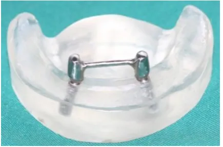
Two acrylic resin copings (Pattern Resin; GC
Corporation, Tokyo, Japan) were first fabricated on the
abutments and were subsequently splinted with a plastic
sheet of 2 mm in diameter and then cast with a
gold-palladium alloy (Degobond 4; Degussa, Germany) to
provide a reference framework. The corresponding
abutment screws provided the connection between the
abutments and implants. (Figure 3)
Figure 3: Metal framework served as a reference bar to de-termine vertical gaps.
The implants were, secured to the acrylic cast with
an epoxy resin adhesive (RS Components; Corby,
Eng-land). The reference bar was placed over the abutments.
The framework was removed from the master cast only
after polymerization of the epoxy resin was complete.
[11] Thus, any discrepancy that could have been caused
by the casting procedure was eliminated and a definitive
cast with a passively fitting framework was produced.
This reference bar was used to verify the accuracy of
casts that had been produced from various impressions.
To assess the accuracy of the produced casts, the
verti-cal-fit discrepancy of this reference framework was
measured as it related to the abutments when placed
passively onto the working cast with the aid of a
stere-omicroscope (Leica Microsystems; Wetzlar, Germany).
[17]
For impression tray design, an impression of the
definitive cast was made to which two impression
cop-ings were attached with an irreversible hydrocolloid
(Tropicalgin; Zermack SpA, Badia, Italy). The
impres-sion was poured with type IV dental stone (Elite Master;
Zermack SpA, Badia Italy). Two tissue stops were
placed into a 1-mm thick wax sheet (Modeling Wax;
Dentsply Ltd., Weighbridge, UK) that were then placed
over the residual ridge, posterior to the impression
cop-ings that were blocked out with a 3-mm wax layer. A
third tissue stop was incorporated between the implants.
Three location marks (buccal, distal and lingual)
were made and included in the impression trays to
standardize tray positioning during impression making.
An individual autopolymerizing acrylic resin tray
(Uni-fast Trad; GC Corporation, Tokyo, Japan) was initially
made from this cast and then cast with a cobalt-chrome
(Co-Cr) alloy. The cast tray was 2-mm thick with two
openings on top of the tray to allow fastening and
unfas-tening the impression coping screws when using any
direct impression-making technique. In addition,
vari-ous bolts and nuts were employed to allow generic
one-eighth inch screws to be used to fasten the tray to the
top part of a custom-fabricated impression-making jig.
[23]
The definitive cast was fixed with three screws to
the stainless steel base of this jig to prevent cast
move-ment during impression making. The
impression-making tray was slid in a vertical direction along four
custom-fabricated parallel guiding steel pins (11mm in
diameter) affixed to the base. This jig provided a single
insertion and removal axis that could move in a defined
path at the time of the seating and rising phase and
pro-vided the exact same condition for all
impression-making situations. (Figure 4) [23]
The fitting surfaces of all components were
cleaned with isopropyl alcohol before making each
im-pression. [24] The impression copings were first
at-tached to the definitive cast and all open- and
Figure 4: The impression jig used to take impressions
Figure 5: Group1 closed-tray transfer snap-fit technique mod-el
ants on the master cast to engage the hex. Correct
seat-ing of the impression post was verified by a
prosthodon-tist with 30 years of professional experience, who made
a continuous visual and tactile inspection of the
place-ment of the coping throughout the impression-making
and pouring procedures. Four groups of five casts each
were used to evaluate the following impression-making
techniques:
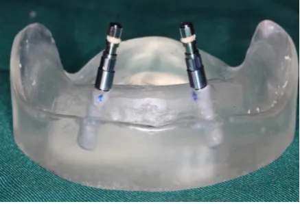
Group 1: Closed-tray transfer snap-fit
Two closed tray impression copings with snaps were
fastened to the two implants in the definitive cast to
engage the hex using 15 N/cm of torque. [25] (Figure 5)
Group 2: Open-tray nonsplinted impression post
Two square open-tray impression copings were used to
transfer the angulated position of the implant. These two
open-tray impression copings were fastened onto the
two implants in the definitive cast to engage the hex
using 15 N/cm of torque. [25] (Figure 6)
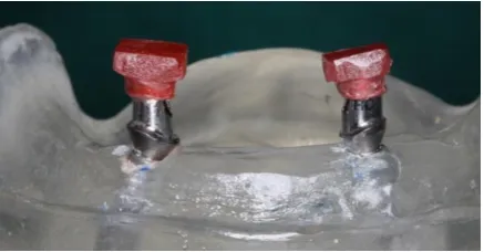
Group 3: Metal splinted impression post
Straight metal (Co-Cr) rods, 2.35mm in diameter,
af-fixed with small amounts of acrylic resin (Pattern resin
GC Corporation; Tokyo,Japan), were used to attach two
Figure 6: Group 2 open-tray non-splinted impression coping technique model
Figure 7: Group 3 metal splint impression coping technique model
square impression copings to each other in an open tray
at the level of the circumferential groove to ensure
secu-rity. [17] (Figure 7)
Group 4: Custom-made acrylic resin transfer cap
Two custom-made acrylic resin transfer caps were made
of Pattern acrylic resin (GC Corporation; Tokyo, Japan).
They were placed over two angled titanium abutments
(RC Anatomic Abutment; angled at 15°; Straumann
AG, Basel, Switzerland) (similar transfer caps
tech-nique). [26] Finally, during the impression making
pro-cess were seated on each angulated abutment that had
been placed on the two implants in the definitive cast to
engage the hex by using 15N/cm of torque. (Figure 8)
In liberator, for making custom-made acrylic resin
transfer cap after attachment of abutment to implant
analog, the screw access hole was filled by light body
impression material (Panasil; Kettenbach, Germany) to
prevent penetration of acrylic impression material into
it. The abutment was lubricated by Vaseline. The cap
was made by pattern acrylic resin (GC Corporation;
Tokyo, Japan) by using brush technique. Having
pol-ymerized the first layer, more resin layers were added to
the cap surface to form square and retentive forms, so
that it would be easily picked up after impression-
mak-ing procedure. The end point of cap was marked by
taper carbide bur 699 (ELA; Germany) to check
re-seating of cap. During impression making, the abutment
was detached from the implant and put in impression in
line with the marking sign.
Impression making material
The impression materials were left at workroom
tem-perature for one hour in the working environment prior
to mixing. [23] The custom tray was covered with VPS
adhesive (Reto; Kettenbach, Germany) and left to dry
for 15 minutes. Additional monophase silicone
impres-sion making material (Monopren Transfer; Kettenbach,
Germany) was mixed with a manual gun dispenser
(Ap-plyfix 4; Kettenbach, Germany). At the impression
making time of each group of samples, this material was
injected around group 1 and 2 impression copings,
group 3 metal-splinted copings, and group 4
custom-made acrylic resin caps as needed. The loaded tray was
placed on the guiding pins of the impression jig and,
using hand pressure, slid down onto the definitive cast
until it contacted the tissue stops on the master cast. The
tray with the impression material was left undisturbed
for 10 minutes on the definitive cast to polymerize.
The manufacturer-recommended setting time was
doubled to compensate for the delayed polymerization
reaction at room rather than at mouth temperature. [24,
26] A 1.25-kg force was exerted over the tray by the
weight of the upper jaw of the jig during the impression
procedures. (Figure 4) This pressure was enough to
force the excess material to flow outward and it was
maintained throughout the working time until the
polymerization process completed. [11, 18]
In the group with closed-tray technique, the
im-pression copings remained on the definitive cast until
complete polymerization of the impression material and
removal of the tray. These impression copings were
removed from the definitive cast one at a time and
at-tached to the implant analog. The custom-assembled
impression coping analog unit was inserted into the
im-pression by firmly pushing it downward into place to its
full depth, and then slightly rotating the unit clockwise
to feel for the anti-rotational resistance. This tactile test
confirmed that the grooves on the coping were properly
engaged and locked into place besides that the implant
position was accurate. [27]
In groups with open-tray and metal splinted
meth-od, the impression copings were unscrewed and the tray
was separated from the definitive cast. The implant
ana-logs were then attached and tightened to the impression
copings by hand.
In thegroup 4wherein the cap was made from an
angulated abutment just as in those wherein the
closed-tray method was used, the impression coping was
fas-tened to the analog unit and pressed into the impression.
A two-time pouring technique was employed to
minimize any setting expansion of the dental stone. Two
pieces of latex tubing, each 23×4×8 mm (length ×
inter-nal diameter × exterinter-nal diameter), were used. [11, 17]
The tubes were fitted onto the analogs and poured with
die stone (Elite Master;Zermack SpA, Badia, Italy) two
hours after the impressions were madeby using a ratio
of 21 ml of water to 100 g of stone powder. [11, 17]
After the initial setting phase of approximately 10
minutes, the latex tubes were removed. (Figure 9)
Figure 9: Latex tubes removed from implant analogs
A ratio of 2.5 ml of water to 10 g of die stone
powder was mixed following the previously described
process, injected by using a 20-ml Plastipak syringe
(Soha; Karaj, Iran) around the analogs, and wasallowed
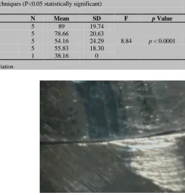
Table 1: One-way ANOVA used to compare the four techniques(P<0.05 statistically significant)
Technique Study Groups* N Mean SD F p Value
Closed-tray transfer snap fit (1) 5 89 19.74
8.84 p < 0.0001 Open-tray non-splinted impression coping (2) 5 78.66 20.63
Metal splint impression coping(3) 5 54.16 24.29 Custom-made acrylic transfer cap (4) 5 55.83 18.30
Definitive cast 1 38.16 0
* Group numbers in parenthesis, N=Number, SD=Standard Deviation
Figure 10: The casts trimmed for measuring
ons. [14] The 20 casts comprising the four technique
study groupswere stored at room temperature for a
min-imum of two weeks before measurement. [24]
Each cast was then trimmed and marked with a
specifically designated number. (Figure 10) All casts
were prepared by the same prosthodontist.
For the concentricity measurements, two
angulat-ed abutments (RC Anatomic Abutment; anglangulat-ed at 15°,
Straumann AG, Basel, Switzerland) were connected to
the implants on each cast and two titanium screws were
tightened on the right and left analogs at 15 N/cm torque
in the same position. As described previously, it was
done by using a torque driver to ensure visually that the
angulated abutments were parallel. The standard
framework was seated on the abutments and the
abut-ment-framework interface gaps were measured on
vari-ous analogs. Before measuring procedure, the metal
framework was cemented on the abutments with Temp
Bond Clear (Kerr Corporation; Orange, USA). A clamp
was used to maintain the constant seating pressure of 25
N/cm for 5.5 min. [28]
The bar fit accuracy was then quantified by
meas-uring the vertical gaps between the copings and the
sample implant analogs by using a stereomicroscope
(Leica Microsystems; Wetzlar, Germany) (Figure 11) at
three pointson each right and left analog at ×100 mag
Figure 11: Image of the distal abutment-framework interface gap (100× magnification)
nification. [28] The same measurement protocol was
used for all cast throughout the study. The subsequent
measurements performed on the casts were made by the
same prosthodontist. Three demarcations (buccal, distal
and lingual) were made on each framework to have
standardized measurements within identical framework
area in each cast.
The mean of these three measurements
deter-mined the size of the gaps in the right or left framework.
The mean gap value for each group was calculated
based on the average of five consecutive measurements
(10 gap values). Various comparisons of the gap
dimen-sions were performed via one-way ANOVA and a post-hoc value of p< 0.05 was considered statistically
signif-icant.
Results
In our results, the mean fit accuracy was measured by
vertical gap measurements in casts representing four
impression making techniques. A total of 20 casts were
fabricated in four groups (n=5). Approximately 120 gap
values were calculated. The results are presented in
Ta-bles 1 and 2.The mean values of the master cast were
significantly different from those of groups 1 and 2, but
not from groups 3 and 4 (Table 2). In addition, the
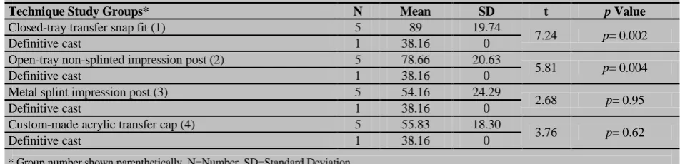
Table 2: Post hoc one-sample t-test used to compare the study groups (μm) with the definitive cast (P<0.05 statistically significant)
Technique Study Groups* N Mean SD t p Value
Closed-tray transfer snap fit (1) 5 89 19.74
7.24 p= 0.002
Definitive cast 1 38.16 0
Open-tray non-splinted impression post (2) 5 78.66 20.63
5.81 p= 0.004
Definitive cast 1 38.16 0
Metal splint impression post (3) 5 54.16 24.29
2.68 p= 0.95
Definitive cast 1 38.16 0
Custom-made acrylic transfer cap (4) 5 55.83 18.30
3.76 p= 0.62
Definitive cast 1 38.16 0
* Group number shown parenthetically, N=Number, SD=Standard Deviation
ant difference between groups 1 and 4, as well as
be-tween groups 2 and 4 (p≤ 0.001). Statistically
signifi-cant differences were also observed between groups 1, 2
and 3 (p< 0.05). However, the difference between
groups 3 and 4 was not statistically significant.
Discussion
The relationship of a prosthetic superstructure to its
underlying implant abutments is considered as the
pas-sive fit. Yet, no precise definition or describing
parame-ters for passive fit have been established as a passive fit.
The first stage in achieving an accurate, passively fitting
prosthesis is to reproduce the intraoral relationship of
the implants with the use of impressions. [8] However, a
perfect fit is obtained when all the matching surfaces of
the implant and prosthesis are contacted with each other
without exerting any forces. [8]
In this study, a gap of 38.16 μm was still observed
between the framework and the abutment analogs.
However, the master cast was produced by using a
met-al framework. Four techniques as previously named
were used to compare the accuracy of impression by
measuring the vertical gaps and showed no significant
difference between groups 1and 2 in agreement with
several authors. [29-30] However, there were greater
gaps seen in these groups.
In this study, making impressions via group 2 did
not show any statistically significant difference in
com-parison with group 1 from a precision point of view,
which is in contrast with previous studies. [7, 13, 15]
This could be due to the 30°-angulation of the implants
with one another in this study in which these two
tech-niques, i.e. group 1 and group 2caused lower precision
of the impression in comparison with the two other
group 3 and group 4. However, this finding concurred
with the results of Carr’s investigation[29] in which no
statistically significant difference was observed between
these two techniques.
In the present study, gap reduction was observed
in samples of group 3, indicating the superiority of this
method over other techniques. It showed that splinting
significantly increased the precision of impression
mak-ing as demonstrated by previously conducted
aforemen-tioned study in which the implants were 30° angulated.
[18-20] Similarly, the current investigation found that
splinting increased the precision where the implants
were angulated toward each other.
Lee et al. [31] found that open-tray nonsplinted
impression coping and closed-tray transfer coping
tech-niques had similar accuracy for making impressions of
three or fewer implants. However, in this investigation
where two implants were at 30° angle with each other,
the group 3 open-tray metal splinted impression coping
was significantly superior and was quite more precise
than group 2.
Findings of this study indicated that making an
accurate impression through the method used in group 3
definitely depended on the type of splint used, a result,
which was in agreement with previously published
in-vestigative reports. [18-19] This difference in results
could be due to the angulation of implants (30°) used in
the present study. However, this finding was also in
conflict with various other investigations. [13-15]
Earlier studies showed that a more accurate
work-ing cast could be obtained by uswork-ing the metal-splinted
impression copings technique. [17] It confirms that the
accuracy of group 3 and 4 was similar,and that both of
these methods produce more accurate impressions than
those by group 1 and 2.
The current study noted that the angles of implants
were compensated for through utilizing angulated
those of group 3,were significantly more accurate than
group 2 and 1. It indicated that this technique was
ac-companied with the least distortion of impression-
mak-ing material and, therefore, offered higher accuracy.
These were in line with previous findings about
the snap-fit technique. [24, 32-33] It explained the
simi-larity of the plastic impression caps used in the
nonsplinted impression-making methods and the acrylic
resin splint impression technique for transferring the
position of multiple intraoral implants to a laboratory
definitive cast. [24]
Choi et al. [22] explained that an implant
angula-tion of ≤8o was the maximum divergence that permitted
easy removal of the splinted or nonsplinted impression
copings. There is negative relationship between the
im-plant angulation and impression accuracy. [12, 34]
In this study, by having an implant angulation
higher than 8° (30° in our case), the impression
accura-cy could be improved and vertical fit discrepancies were
prevented in any impression-making technique. The
group 4 custom-made acrylic resin transfer caps were
placed over the abutments. The accuracy of this method
was similar to metal splintedtechnique described earlier
by Del’Acqua et al.; [17] however, they achieved
dif-ferent results when using the splinting custom-made
acrylic resin transfer caps with acrylic resin.
Conclusion
Within the limitation of this in vitro study, it may be
concluded that the rigid metal-splinted impression
cop-ing and the custom-made acrylic resin transfer cap
tech-niques produce significantly more accurate impressions
than the snap-fit transfer coping and the non-splinted
pick-up method. It suggests that custom-made acrylic
resin (indirect) transfer cap technique might be a
relia-ble impression- making method in angulated implant
position.
Conflict of Interest
None declared.
References
[1] Schneider A, Kurtzman GM, Silverstein LH. Improving implant framework passive fit and accuracy through the use of verification stents and casts. J Dent Technol. 2001; 18: 23-25.
[2] Akça K, Cehreli MC. Accuracy of 2 impression tech-niques for ITI implants. Int J Oral Maxillofac Implants. 2004; 19: 517-523.
[3] Chee W, Jivraj S. Impression techniques for implant dentistry. Br Dent J. 2006; 201: 429-432.
[4] Al Quran FA, Rashdan BA, Zomar AA, Weiner S. Pas-sive fit and accuracy of three dental implant impression techniques. Quintessence Int. 2012; 43: 119-125. [5] Goodacre CJ, Bernal G, Rungcharassaeng K, Kan JY.
Clinical complications with implants and implant pros-theses. J Prosthet Dent. 2003; 90: 121-132.
[6] Sahin S, Cehreli MC. The significance of passive frame-work fit in implant prosthodontics: current status. Implant Dent. 2001; 10: 85-92.
[7] Goll GE. Production of accurately fitting full-arch im-plant frameworks: Part I--Clinical procedures. J Prosthet Dent. 1991; 66: 377-384.
[8] Assif D, Marshak B, Schmidt A. Accuracy of implant impression techniques. Int J Oral Maxillofac Implants. 1996; 11: 216-222.
[9] Mostafa TM, Elgendy MN, Kashef NA, Halim MM. Evaluation of the precision of three implant transfer im-pression techniques using two elastomeric imim-pression materials. Int J Prosthodont. 2010; 23: 525-528.
[10]Faria JC, Silva-Concílio LR, Neves AC, Miranda ME, Teixeira ML. Evaluation of the accuracy of different transfer impression techniques for multiple implants. Braz Oral Res. 2011; 25: 163-167.
[11]Del'Acqua MA, Arioli-Filho JN, Compagnoni MA, Mol-lo Fde A Jr. Accuracy of impression and pouring tech-niques for an implant-supported prosthesis. Int J Oral Maxillofac Implants. 2008; 23: 226-236.
[12]Shankar YR, Sahoo S, Krishna MH, Shameen Kumar P, Kumar TS, Narula S. Accuracy of implant impressions using various impression techniques and impression ma-terials. J Dent Implant. 2016; 6: 29-36.
[13]Humphries RM, Yaman P, Bloem TJ. The accuracy of implant master casts constructed from transfer impres-sions. Int J Oral Maxillofac Implants. 1990; 5: 331-336. [14]De La Cruz JE, Funkenbusch PD, Ercoli C, Moss ME,
Graser GN, Tallents RH. Verification jig for implant-supported prostheses: A comparison of standard impres-sions with verification jigs made of differentmaterials. J Prosthet Dent. 2002; 88: 329-336.
Dent. 1993; 69: 588-593.
[16]Yamamoto E, Marotti J, de Campos TT, Neto PT. Accu-racy of four transfer impression techniques for dental im-plants: a scanning electron microscopic analysis. Int J Oral Maxillofac Implants. 2010; 25: 1115-1124. [17]Del Acqua MA, Chavez AM, Castanharo SM,
Com-pagnoni MA, Mollo Fde A Jr. The effect of splint materi-al rigidity in implant impressiontechniques. Int J Ormateri-al Maxillofac Implants. 2010; 25: 1153-1158.
[18]Assuncao WG, Filho HG, Zaniquelli O. Evaluation of transfer impressions for osseointegrated implants at vari-ous angulations. Implant Dent. 2004; 13: 358-366. [19]Vigolo P, Fonzi F, Majzoub Z, Cordioli G. An evaluation
of impression techniques for multiple internalconnection implant prostheses. J Prosthet Dent. 2004; 92: 470-476. [20]Vigolo P, Majzoub Z, Cordioli G. Evaluation of the
accu-racy of three techniques used for multipleimplant abut-ment impressions. J Prosthet Dent. 2003; 89: 186-192. [21]Michalakis KX, Kalpidis CD, Kang K, Hirayama H. A
simple impression technique for dental implants placed in close proximity or adverse angulations. J Prosthet Dent. 2005; 94: 293-295.
[22]Choi JH, Lim YJ, Yim SH, Kim CW. Evaluation of the accuracy of implant-level impressiontechniques for inter-nal-connection implant prostheses in parallel and diver-gent models. Int J Oral Maxillofac Implants. 2007; 22: 761-768.
[23]Aguilar ML, Elias A, Vizcarrondo CE, Psoter WJ. Anal-ysis of three-dimensional distortion of two impression-materials in the transfer of dental implants. J Prosthet Dent. 2010 Apr; 103: 202-209.
[24]Burawi G, Houston F, Byrne D, Claffey N. A comparison of the dimensional accuracy of the splinted and unsplint-ed impression techniques for the Bone-Lock implant sys-tem. J Prosthet Dent. 1997; 77: 68-75.
[25]Ivanhoe JR, Adrian ED, Krantz WA, Edge MJ. An im-pression technique for osseointegrated implants. J Pros-thet Dent. 1991; 66: 410-411.
[26]Lorenzoni M, Pertl C, Penkner K, Polansky R, Sedaj B, Wegscheider WA. Comparison of the transfer precision of three different impression materials in combination with transfer caps for the Frialit-2 system. J Oral Rehabil. 2000; 27: 629-638.
[27]Conrad HJ, Pesun IJ, DeLong R, Hodges JS. Accuracy of two impression techniques with angulated implants. J Prosthet Dent. 2007; 97: 349-356.
[28]Oyagüe RC, Turrión AS, Toledano M, Monticelli F, Osorio R. In vitro vertical misfit evaluation of cast frameworks for cement-retained implant-supported par-tial prostheses. J Dent. 2009; 37: 52-58.
[29]Carr AB. Comparison of impression techniques for a two-implant 15-degree divergent model. Int J Oral Maxil-lofac Implants. 1992; 7: 468-475.
[30]Cabral LM, Guedes CG. Comparative analysis of 4 im-pression techniques for implants. Implant Dent. 2007; 16: 187-194.
[31]Lee H, So JS, Hochstedler JL, Ercoli C. The accuracy of implant impressions: a systematic review. J Prosthet Dent. 2008; 100: 285-291.
[32]Daoudi MF, Setchell DJ, Searson LJ. A laboratory inves-tigation of the accuracy of two impression techniques for single-tooth implants. Int J Prosthodont. 2001; 14: 152-158.
[33]Cehreli MC, Akça K. Impression techniques and misfit-induced strains on implant-supported superstructures: an in vitro study. Int J Periodontics Restorative Dent. 2006; 26: 379-385.