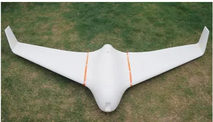
Design and Construction of Hand-Launched Flying Wing RC Aircraft
Aung Lwin Moea, Aye Aye Pyonea
a
Department of Propulsion and Flight Vehicles, Myanmar Aerospace Engineering University Myanmar
Abstract This paper covers the basic tools and concepts required to develop the new design of hand-launched Flying Wing unmanned aerial vehicle that will survive for next generation of students who are interested in this environment. This paper presents not only the actual layout, the basic concepts and loading analysis, performance analysis, software analysis, static stability check and dynamic stability check for our project but also the actual construction layout with difficulties which seek in construction and the analytical process used to determine how the predicted design should be modified to better meet the requirements. The initial design sizing is developed by the reference of Skywalker Mini version. The performance analysis, the loading effects, static stability checks and dynamic stability checks on the predicted design are also calculated by hand, by Microsoft Excel and MATLAB Software. Static structure deformation and stability analysis of FEE – 004, the point of interest on our project, is checked by “ANSYS FLUENT 19” software for decreasing risks. Then the detail drawing of the predicted design is developed by both Auto-CAD and Solid Work Software. Construction techniques and experiences are reported in step-by-step procedures with many illustrative visual aids.
© 2018 Published by IJRP.ORG. Selection and/or peer-review under responsibility of International Journal of Research Publications (IJRP.ORG)
Keywords: hand-launched; UAV;
International Journal of Research Publications
Volume-21, Issue-1,January 2019
Accepted and Published Manuscript
Design and Construction of Hand-Launched Flying Wing RC Aircraft
Aung Lwin Moe, Aye Aye Pyone
PII : Aung Lwin Moe.10021112019498
DOI: 10021112019498
Web: http://ijrp.org/paper-detail/499
To appear in: International Journal of Research Publication (IJRP.ORG)
Received date: 17 Jan 2019
Accepted date: 05 Feb 2019
Published date: 07 Feb 2019
Please cite this article as: Aung Lwin Moe, Aye Aye Pyone , Design and Construction of Hand-Launched
Flying Wing RC Aircraft , International Journal of Research Publication (Volume: 21, Issue: 1),
http://ijrp.org/paper-detail/499
International Journal of Research Publications
Design and Construction of Hand-Launched Flying Wing RC
Aircraft
Aung Lwin Moe
a, Aye Aye Pyone
aaDepartment of Propulsion and Flight Vehicles, Myanmar Aerospace Engineering University
Myanmar
Abstract
This paper covers the basic tools and concepts required to develop the new design of hand-launched Flying Wing unmanned aerial vehicle that will survive for next generation of students who are interested in this environment. This paper presents not only the actual layout, the basic concepts and loading analysis, performance analysis, software analysis, static stability check and dynamic stability check for our project but also the actual construction layout with difficulties which seek in construction and the analytical process used to determine how the predicted design should be modified to better meet the requirements.
The initial design sizing is developed by the reference of Skywalker Mini version. The performance analysis, the loading effects, static stability checks and dynamic stability checks on the predicted design are also calculated by hand, by Microsoft Excel and MATLAB Software. Static structure deformation and stability analysis of FEE – 004, the point of interest on our project, is checked by “ANSYS FLUENT 19” software for decreasing risks. Then the detail drawing of the predicted design is developed by both Auto-CAD and Solid Work Software. Construction techniques and experiences are reported in step-by-step procedures with many illustrative visual aids.
© 2018 Published by IJRP.ORG. Selection and/or peer-review under responsibility of International Journal of Research Publications (IJRP.ORG)
1.Introduction
A radio-controlled aircraft (RC aircraft) is a small flying machine that is controlled remotely by an operator on the ground using a hand-held radio transmitter. Building RC aircrafts has been growing worldwide with the advent of more efficient motor and lighter and more powerful batteries and less expansive radio systems.
Even after more than a century of research and development the flying wing is still viewed as a unique and unconventional aircraft concept. This reality is even more surprising when you consider the significant aerodynamic and structural benefits afforded flying wing designs, compared to conventional designs. Historical reviews on this topic appear to point to a variety of reasons for the slow acceptance of flying wing type vehicles. From a technical point of view, the dominant issue has been stability and control, which to this day continues to plague this class of vehicle. As a result, flying wing aircraft continue to be limited to missions comprised of only low lift (cruise) conditions. In addition to the technical issues, there were cultural issues faced by this class of aircraft that consisted of negative public perceptions and politics. In the first half of the 20th century, which was the most prolific period of flying wing development, these two issues severely restricted technical discussions and as a result the opportunity to mature this concept was lost.
The present cultural environment is slightly improved but the public perception and politics continue to haunt this concept today. A review of the most recent aircraft design studies shows a significant number of flying wing concepts are under consideration, especially for military applications. It is clear that the realization of the flying wing concept is benefiting from recent technological advances in aerodynamics, flow control, flight control systems, materials, structures and propulsions systems. It also appears that the cultural barriers of the past are also deteriorating allowing for the rich body of flying wing research to be shared and studied and thus, contribute to future vehicle development activities. However, a review of the ongoing research indicates that we continue to re-create the past instead of learning from the past to create the future. These sentiments are clearly stated through the following quotes from A. R. Weyl, 1944.
"...Flying Wing, in which at the present period more interest than ever is being displayed."
"...it seems a fact that experience collected in the past with tailless airplane is either unknown or forgotten or, at the least ill-judged..."
"...it is by no means sufficient that a crazy design flies; it must fly far better than everything else in order to raise attention among those closed circles..."
The following definition of the All-Lifting-Vehicle (ALV) is offered:
A vehicle that has all horizontal orientated elements (i.e., wing, fuselage, tail, etc.) are continuous and aero dynamic ally shaped to contribute proportionally equivalent amounts of lift throughout the flight envelope.
This broad definition allows for the inclusion of all existing definitions for flying wing, all-wing, tailless, and lifting body. Note, the above definition does not allow for a vehicle that has a fuselage that does not provide appropriate lift, a tail/canard that only functions as a trim/control surface, or a nacelle that only houses the propulsion system. The various names that make up the ALV category are as diverse as the concepts themselves and vary from flying wing to flying fuselage. Definitions of the six specific concepts to be investigated are listed below to assist the reader.
Flying Wing
A tailless airplane accommodating all of its parts within the outline of a single airfoil. All-Wing
Aircraft consisting of nothing but wing. (Jack Northrop's definition)
Tailless
Flying Fuselage
An aircraft consisting of an aerodynamically shaped fuselage that generates a majority of the total aircraft lift.
Lifting Fuselage
A thick aerodynamically shaped body with section lift characteristics equivalent to that of a wing. Lifting Body
Aircraft that chiefly or solely generate lift by their bodies.
The discussion presented within the paper will use the Flying Wing (FW) and Flying Fuselage (FF) terms as the primary ALV descriptors with All-Wing and Tailless being sub-elements of FW and Lifting Fuselage and Lifting Body as sub-elements of FF.
A goal of this paper is to provide context and perspective for present and expected future aircraft design studies that may employ the ALV concept. It is also hoped that this paper will demonstrate the benefit of developing an understanding of the past in order to obtain the required knowledge to create future concepts with significantly improved aerodynamic performance.
2.Design
We designed our FEE 004 from Skywalker X8 mini (Atom) version shown in fig .2. We denoted the mission requirements for our flying wing RC aircraft and calculated step by step.
Fig. 1. Skywalker X8 mini (Atom) version
2.1.Mission Requirements
Table 1. Mission Plan
Total Weight 5 lb
Stall Speed 24 fps
Cruise Speed 48 fps
Cruise Altitude 600 ft
Endurance 10 min
Propeller Type Pusher
2.2.Designing Parameters
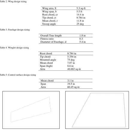
Table 2. Wing design sizing
Wing area, S 5.3 sq-ft Wing span, b 5.5 ft Root chord, cr 14.4 in Tip chord, ct 8.784 in Mean chord, 𝑐 11.8 in
Sweep angle 25 deg
Table 3. Fuselage design sizing
Overall True length 1.8 in
Fitness ratio 0.3
Diameter of Fuselage, d 5.4 in
Table 4. Winglet design sizing
Root chord 8.784 in Tip chord 5.356 in Mounted angle 75 deg Mean chord 7.07 in Span (high) 6.6 in
Area 46.662 sq-in
Table 5. Control surface design sizing
Mean chord 3.1 in
Span 19.5 in
Area 60.45 sq-in
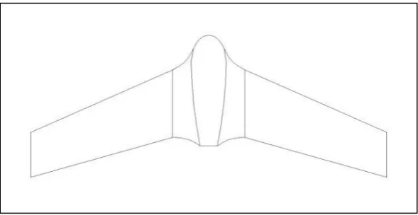
Fig .6. Elevon (All functions controller)
Fig .7. 2D view of FEE-004
3.Propulsion Units Choosing
3.1.Designing Parameters
According to the power 490W needed by FEE-004, we’d use cobra 3525/7T 780 Kv brushless motor that had minimum of 450 W to maximum of 850 W.
3.2.Battery (Main Power Source) Selection
The main power source was chose from the motor reference data sheets that described the limitations between 3 cells and 5 cells. It based to choose on the designer’s mission requirement as endurance. So, we chose 2600 mAh 4 cells battery to serve as a main power source for FEE-004.
3.3.Propeller Selection
3.4.ESC (Electronic Speed Controller) Selection
To fully control the motor’s speed, we chose 60A ESC from data analysed testings’ sheet.
3.5.Servos (All Functional Controller) Selection
We selected Henge MD933 12g Metal micro Servos that based on weight of control surfaces and how much fully control the whole aircraft.
3.6.3-axis Stabilizer
To be compensated gains for controller (RC Pilot) any conditions on air, we chose it. The main function of this device is to help aircraft’s stability by giving re-direction of the aircraft to equilibrium position if meeting disturbents while flying.
3.7.DV mini Camera
We aimed that our FEE-004 was used in aerial photographing so, we used this camera to serve this mission.
4.Stability Check
4.1.Static Stability
The requirements for static stability were developed for longitudinal, lateral, directional and rolling motions. It is easy to see why a pilot would require the airplane that he is flying to possess some degree of static stability. Without static stability the pilot would have to continuously control the airplane to maintain a desired flight path, which would be quite fatiguing. The degree of static stability desired by the pilot has been determined through flying quality studies. The important point at this time is to recognize that the airplane must be made statically stable, either through inherent aerodynamic characteristics or by artificial means through the use of an automatic control system.
Finally, the relationship between static stability and control was examined. An airplane that is very stable statically will not be very manoeuvrable; if the airplane has very stable, it will be very manoeuvrable. The degree of manoeuvrability or static stability, it will be very manoeuvrable. The degree of manoeuvrability or static stability is determined by the designer on the basic of the airplane’s mission requirements.
We checked that our FEE - 004 is whether statically stable or not by using the longitudinal, lateral and
directional stability. According to the calculations in this chapter, we found that the pitching moment curve is negative slope which gives the positive pitching moment and the measures of control derivatives are suitable for theoretical concept for our flying wing. So our flying wing is statically stable and then goes to dynamic stability.
4.2.Dynamic Stability
aircraft while flying on air, was calculated and got response curves and graph from MATLAB with inputting step inputs. All of modes was situated in the limitation of response and FEE-004 was be dynamically stable.
5.Software Check
5.1.Software analysis on aerodynamics
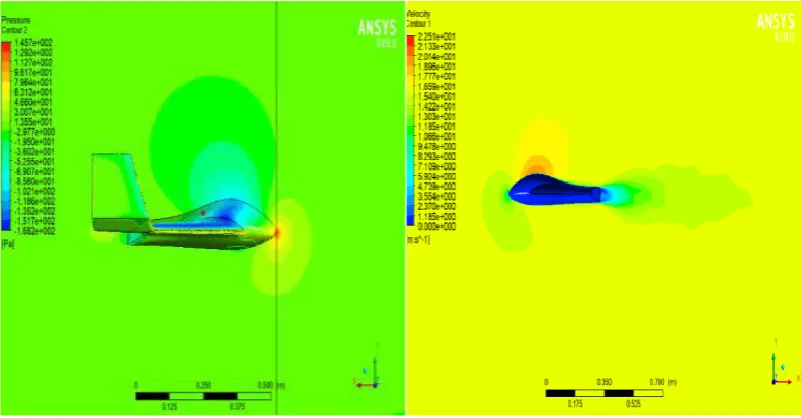
We used ANSYS FLUENT 19 to obtain the aerodynamic parameters, velocity distribution and pressure distribution on the 3D geometry of our airplane FEE-04.
Firstly, we drew the entire aircraft from the calculated design parameters in the Solidwork 2018, saved as parasoild extension and imported to the Ansys design modeller (space claims). but only half of the entire design was used for analysis. This was because, the processing time and power required for the entire plane to be analysed was very high.
The steps we used are as follows
Fig .9. Pressure contour & Velocity contour at α = 12’
According to these contour, the pressures acting on the most convex surface of the airplane are nearly minimum and the velocity maximum. As the angle of attack of the aircraft increases, the minimum and maximum pressure acting on the aircraft decrease and the maximum velocity increases. This occurrence also prove the Bernoulli’s Principle. And the as we can see the pressure will be maximum at tip of the object which is the beginning of the contact surface. The surface which is not in the direct path of the airflow, the hind surface, will have the minimum velocity.
5.2.Ansys Analysis on Static Structure
A static structural analysis determines the displacements, stresses, strain, and forces in structures or components caused by loads that do not induce significant inertia and damping effects. Steady loading and response conditions are assumed; that is, the loads and the structure to vary slowly with respect to time.
We used the materials: Styrofoam for the aircraft and 5- 3.5 cm radius hollow aluminium for the spur added to the aircraft at quarter cord.
Fig .11. Total deformation on FEE – 004 with spur at 16 m/s (cruise speed)
The main purpose of this section is for detail analysis and further design optimizations. We can easily calculate 2D parameters by hands. But for 3D calculation, the steps become more and more complex and hard to find accurate and reliable solution by hand calculations only. So, the helps forms the CAD software are inevitable. Among them, ANSYS is popular and quite reliable software for flow analysis and other structural calculations.
The flow type we used for this analysis is steady flow which does not change with time and the structural analysis type is static. In practical, the conditions are always varying with time which means unsteady flow and dynamics structural conditions. The software we used can perform such dynamics calculations but that will require a great power of calculation devices, super computer, to be an effective calculation. Because even in the static condition calculation, it require nearly 12 hours of overall processing time (excluding processing errors, input errors and correction times).
6.Conclusion
6.1.Construction Experiences
Intends to discuss about our hand-launched flying wing configuration, construction experience and some difficulties deal with during construction period. Practical construction is slightly different with theoretical calculation. Our aircraft is constructed mainly with bluish thick foam, thin balsa wood for additional structural strength, aluminum spurs and spokes and 502 super glue for attachment, 12 V DC adapters for foam cutting, and other various hand tools’ aid. There are many errors, already overcome with the team spirit, hard working with patience like,
1. Cutting error 2. Human error
3. Power supply (fluctuation of voltage) 4. Material error
The wings and most components of our aircraft are mainly constructed with special foam which is usually recommended for the use in small airplanes because it has a high strength to weight ratio. It can be easily formed into the desired shape and design.
In the case of making the wings, first, the foam was cut to get nearly the required wing dimensions. The thin wooden plate was cut into airfoil shape using an appropriate saw.
6.2.Flight Test
After all of the construction and checking analysis were completely finished, we tested our aircraft for first flight. We made this flight test at airfield of Ground Training Base (Meiktila), Myanmar Air Force on September 8 , 2019 17:20. This was a successfully flight for FEE-004’s first flight.
6.3.Discussion and Conclusion
In this project, the main purposes are to get design and theoretical knowledge, to know how to construct a tailless flying wing with good performance and to develop creative thinking in making a project with good team spirit and to provide next generations who wish to construct tailless flying wing as a useful and helpful project paper. For later a half of century, many scientists in aeronautical field would like to forecast that flying wing business jets will use in civil aviation.
Many difficulties were undergone in not only learning theory to apply and calculation, but also in construction with design limitations in our project’s theoretical calculations and actual construction. As first, theoretical calculations, this project paper was divided into six parts (design configuration, performance, static stability, dynamic stability, loading analysis and software analysis). Those above difficulties were managed to solve by taking nearest possible value compared with empirical results.
In FEE - 004, the pusher type was selected in order to be safe for propeller and also electric motor was
chosen with 490W power supplies. For the whole aircraft, white thick foam was used due to difficulty to find materials (bluish thick foam) and so, had gotten weakness point for electric components casing and for structural strengthening. But we solved this weakness point by reinforcing balsa wood of 1mm thickness was used; covering the wing, fuselage, winglets and endplates. The following difficulties occurred which carefully handled in actual construction;
1. In the progress of shaping airfoil, good skills and right decisions are required in cutting foam to obtain the airfoil shape as design mentioned.
2. If the wing span was too long dimension, the foam was cut into four equal pieces for respective part of wing piece for better shaping airfoil smoothly, but it cause additional airfoil design calculations.
3. Aluminum 3 mm hallow tube spurs were used in joining cut pieces for structural strengthening, but need to care not to deform the airfoil shape and straight of the wing. A groove was also made for filling the spurs throughout the wing’s undersurface and it was hard to glue the spur with the foam piece firmly. Should be mainly noticed the position of spurs reinforced into the wing to be the point which reacted the maximum load (from loading action calculation) while fling.
4. When the motor was mounted to the aircraft, the line of motor thrust is needed to be placed at the center line and rear part of the aircraft. The mounting must be firmly fitted.
5. In the fitting of winglets, they must be fitted with right angle from calculation to the wing’s surface and it was hard to glue the very tiny iron rod with the winglets.
6. Since the control surfaces are very thin, plastic film plate was used to glue with the tapered side respective elevons for strength and light weight.
Lastly, we’d like to chance to inform that if you’ll be interest this project more than this paper, please go to the university’s library and had a read the B.E. project book of,
“Design and Construction of Hand-Launched Flying Wing RC Aircraft” submitted by Flying Eagle Eye group.
Acknowledgements
A project such as this requires assistance of the Flying Eagle Eye group. The members of this group would like to thanks for the guidance and technical supports during all phases of this project.
References
[1] Ansys.com., Ansys Fluent 2019, Available from; http://www.Ansys. com / ansys
[2] Zachary Standridge, Kevin Kochersberger, Ph.D. and James Donnelly, Virginia Polytechnic and State University, USA and
James Weeks, Ph.D., Development Monitors 2, Virginia, USA, “ Design and Development of a Low-Delivery and Mapping
UAV Suitable for production and Operation in Low Resource Environments ,” AIAA Science Technology Forum, 2018.
[3] Japanese Aerospace Team,” Aerodynamic Design of Airfoil for Flying Wing Mars Airplane,” AIAA Aerospace Forum,
2018.
[4] Dr. Pascual Marques, Marques Aviation Ltd, Uk and Dr. Andrea Da Ronch, Aircraft Structural Design University of
Southampton, UK, “Advanced UAV Aerodynamics, Flight Stability and Control,” 2017.
[5] Dr. David K. Schmidt, Professor Emeritus, Department of Mechanical and Aerospace Engineering, University of
Colorado-Colorado Springs Monument, “Stability Augmentation and Active Flutter Suppression of a Flexible Flying-Wing Drone,”
AIAA Science Technology Forum, 2016.
[6] BOREAS XI Group,“Design and Construction of Twin-Boom RC Aircraft ,”B.E. Project, 2016.
[7] Jhon D. Anderson, Jr., “Fundamental of Aerodynamic,” 6td edition, 2016.
[8] Phoenix, “Design and Construction of Hand-Launched Phoenix Flying Wing RC Aircraft,” B.E. Project, 2016.
[9] HobbyKing Store, Skywalker X8 FPV / UAV Flying Wing 2120mm [Internet], 2015, Available from; http://www.hobbyking.co.uk
[10] XFLR5.com., XFLR5 [internet], 2015, Available from; http://www.XFLR5.com/ xflr5
[11] Alexander S. Goodman, Marques Aviation Ltd, USA, “ Conceptual Aerodynamic Design of Delta-type tailless Unmanned
Aircraft,” International Journal of Unmanned Systems Engineering (IJUSEng) Vol. 2, No. S2, 1- 15, 2014 , http://dx.doi.org/10.14323/ijuseng.2014.4
[12] Rensselaer Polytechnic Institute, “Document of AIAA Design Build Fly Competition,”2013.
[13] T. I. Saeed and W. R. Graham, University of Cambridge, CB2 1PZ, England, “Conceptual Design for a Laminar-Flying
Aircraft,” 50th AIAA Aerospace Science Meeting, 2012.
[14] HAND-LAUNCHED Group, “Design and Construction of Hand-Launched Vehicles” B.E. Project, 2011.
[15] School of Innovation, Design and Engineering, Malardalen University, Sweden, “Project Solaris – Analysis of airfoil for
solar powered Flying Wing UAV,” B.E thesis, 2011.
[16] Jhon D. Anderson, Jr., “Introduction to Flight,” 6th edition, 2010.
[17] Gatto, Department of Aerospace Engineering, Brunel University, UK, P. Bourdin, Bombardier Aerospace, Canada and M. I.
Friswell, Professor, school of engineering, University of Swansea, UK, “ Experimental Investigation into Articulated
Winglet Effects on Flying Wing Surface Pressure Aerodynamics ,” Journal of Aircraft Vol.47, No. 5, 2010.
[18] Robert C. Nelson, “ Flight Stability and Automatic Control ,” 2nd edition, 2007.
[19] Denis Howe, “Aircraft Loading and Structural Layout,”2004.
[20] Thomas C. Corke, “Design of Aircraft,” 2003.
[21] Lloyd R. Jenkinson and James F. Marchman III, UK, “Aircraft Design Projects for engineering students,”2003.
[22] Richard M. Wood and Steven X. S. Bauer, NASA Langley Research Center Hampton, Virginia, USA, “Flying Wings/Flying
[23] Jhon D. Anderson, Jr.,“Aircraft Performance and Design”, 1998.
[24] Worcester Polytechnic Institute, “Design and Construction of a Remote Piloted Flying Wing,” NASA/USRA Advanced