© 2019 IAU, Majlesi Branch
The Numerical Modeling to
Study the Multi-Pass Friction
Stir Processing on Magnesium
Casting Alloy AZ91
Hoda Agha Amini Fashami, Mohammad Hoseinpour
Gollo
*, Nasrollah Bani Mostafa Arab, Bahram Nami
Department of Mechanical Engineering, Shahid Rajaee Teacher Training University, Iran
E-mail: [email protected], [email protected]*, [email protected], [email protected]
*Corresponding author
Received: 10 August 2019, Revised: 9 October 2019, Accepted: 1 December 2019
Abstract: In this research, the multi-pass friction stir processing on AZ91 alloy has been simulated with the three-dimensional numerical modeling based on the ABAQUS/ Explicit. This simulation involves the Johnson-Cook models for defining the material behavior during this intense plastic deformation and investing the fracture criterion. Friction stir processing is a complex process that includes several issues such as high strain rate deformation, microstructure evolution, the asymmetric flow of material, and heat. Therefore, the modeling of this process is challenging. This model simulates the tool plunging and stirring phases in the two-pass process. In this paper, to prevent too much damage in the elements during processing, the Arbitrary Lagrangian-Eulerian technique for automatically remeshing of distorted elements has been used. This work shows that the numerical modeling can be an efficient method to study the effect of process parameters on the thermal evolution and the stress distribution. The thermal model was calibrated using the experimental results from the previous works. This model can predict the transient temperature distribution and residual stress field during FSP on AZ91. The results show that the maximum temperature in the advancing side is more than that in the retreating side. In addition, numerical results show that at the end-position of the process, the tool during the lift-up leaves the keyhole region in a compressive stress state.
Keywords: AZ91, Finite Element, FSP, Mechanical Properties, Simulation
Reference: Agha Amini Fashami, H., Hoseinpour Gollo, M., Bani Mostafa Arab, N., and Nami, B., “The Numerical Modeling to Study the Multi-Pass Friction Stir Processing on Magnesium Casting Alloy AZ91ˮ, Int J of Advanced Design and Manufacturing Technology, Vol. 12/No. 4, 2019, pp. 9–16.
© 2019 IAU, Majlesi Branch
1 INTRODUCTION
On the importance of this research, Friction Stir Processing improves the tribological, mechanical, and surface properties through the modification of the microstructure and graining. Since the invention of the FSP, this process has been the subject of much research. However, the information about the multi-pass process is limited, and few studies have been reported on modelling the Multi-Pass Friction Stir Processing. The simulation with sufficient soft wares such as ABAQUS and ANSYS have attracted consideration to identify the material behavior, microstructure evolution, temperature, and stress distribution during this process. Following is some research on this topic. Hibbitt et al. [1] investigated the residual stresses and temperature field during the FSW. Richards developed their model by using two separate heat sources defined with Fortran77 DEFLUX subroutines. The modified model has been used to predict the thermal field around the tool [2]. Tutunchilar et al. [3] modelled the flow of material when the cylindrical pin was used for performing this process. They investigated the material behaviour with the point tracking method. Rahul Jain et al., [4] showed that during FSP on Mg alloys, the material flow around the pin is asymmetric.
Guerdoux and Fourment [5] used 3D Forge3 finite element software based on Arbitrary Lagrangian-Eulerian formulation and automatic remeshing for modelling FSP. Their model can estimate the temperature field, plastic strain distribution, and material flow during FSW on the aluminium alloys. They used the temperature measurements to calibrate their model. Chen et al., [6] investigated the thermal history during FSP using the numerical modelling. They studied the effect of the process parameters (including the geometry of the tool, axial load, the heat transfer coefficient, contact conditions, the tool rotational, and transverse speed) on the thermal history. Schmidt et al., [7] studied the frictional heat producing during friction stir welding using numerical modelling. The model of Darras [8] was used to study the grain size evolution during FSP on Mg alloy AZ31. Aljoaba [9] investigated the flow of material during FSP on Mg alloy with the computational fluid dynamics model.
Yu et al., [10] modelled the transient temperature distribution and material flow during FSP on Mg alloy. Albakri et al., [11] resulted that the progressive speed is the most effective parameters that affected the thermal field and strain distribution during FSP on AZ31. Asadi et al., [12] developed the lagrangian-implicit coupled model to study the temperature and strain distribution during FSP on AZ91 with more precision. Frigaard et al. [13] modelled the heat flow using the 3D finite element software and validated their numerical modelling using temperature measurements. Khandkar et al. [14]
developed the 3D thermal model that can predict transient temperature during FSW on aluminium alloys. Cho et al. [15] simulated the strain hardening, heat, and material flow during FSW on stainless steel using a (2D) model. They reported that the maximum temperature in the AS region is significantly more than that in the retreating side.
Ulysse [16] modelled the thermal history and material flow during FSW with a 3D viscoelastic model. Colegrove and Shercliff [17] modelled “the heat and material flow during FSW on Al alloys” using CFD code, FLUENT. They studied the effect of the initial parameters on the material and heat flow during FSW. Asadi and Tutunchilar et al. [18] used Lagrangian Incremental Formulation, for modelling FSW. Asadi et al. [18], studied the material flow using the point tracking method. Moreover, the results show that maximum deformation in the advancing side is more than that in the retreating side. Chiumenti et al. [19] developed the Arbitrary Lagrangian-Eulerian model. To prevent the distortion of the meshes during the stirring, they used the sliding meshes near the pin. Rest meshes were the Eulerian model.
Recently, Coupled Eulerian-Lagrangian models have been used to simulate the plastic deformation and investigation of the force signal and temperature profile [20]. In recent years, many researchers used the Coupled Eulerian-Lagrangian method to study the FSW. In addition, the Marker Material Method has been used to study the flow of material. The results show that the flow of material in the advancing side is more than that in the retreating side [21]. The insufficient setting of the process parameters during the performing FSW on AA6061 alloy causes the observation of the hook defects [22]. Some studies used the Coupled Eulerian-Lagrangian model to investigate the effect of process parameters on the formation of defects during the FSW process. Ajri and Shin [23] used the Coupled Eulerian-Lagrangian formulation based on ABAQUS/Explicit software to identify the effect of process parameters on the defects such as the excess flash, tunnel defects, hook defects, and cavities.
The results show that the pin appearance (including height and diameter) and tool tilt (the angle between the pin and workpiece) are the most effective parameters on eliminating defects. “The material flow and thermal cycle influence the hook defect in the joint interface during the FSW process”. Mohammad Ali Ansari et al., [24] showed that the Coupled Eulerian-Lagrangian technique is a sufficient method to study this process and adjust the optimum process parameters.
© 2019 IAU, Majlesi Branch essential specifications like considerable strength to
weight ratio, elimination of electromagnetic waves, and vibration damping; AZ91, have attracted attention in different industries like aerospace, military, and shipbuilding. Most of the researchers studied the FSP on magnesium alloys, while the information about the multi-pass FSP is very limited. Therefore, this work aims are the investigation the Multi-Pass Friction Stir Processing through the simulation approach. Here, a three-dimensional model was prepared to study the thermal history, stress and, temperature distribution, during Multi-Pass Friction Stir Processing on AZ91. The model predicts the maximum temperature that affected the dynamic recrystallization condition. The effect of process parameters on the thermal history and stress field can be determined using this developed model. In addition, the numerical study of residual stress after Friction Stir Processing, in the future, can be compared with empirical results.
2 NUMERICAL MODEL DETAILS
In this paper, the assumptions for solving the problem are as follows: (1) the tool and work piece has been modelled as the 3D deformable materials; (2) the friction coefficient (for investigation the frictional energy) is independent of temperature and process conditions; (3) the thermal, physical and mechanical properties of the work piece are temperature dependent; and (4) the free surfaces of the work piece and the instrument were surrounded by the atmosphere at the ambient temperature. The geometry of the tool is shown in “Fig. 1”. The rotational speed is 146 rad/s, and the tool plunge velocity is not constant. The stages and process timing of the friction stir processing in two passes are shown in “Table 1ˮ.
Fig. 1 The FSP tool used in the process (dimensions in mm).
Table 1 The plunge and traverse stages in two-pass FSP Plunge stage Traverse stage First Pass 0 to 8 s 8 to 18 s Second Pass 19.64 to 28.64 s 28.64 to 38.64 s
3 MATERIAL MODEL
In this present work, the material of the casting plate is AZ91. The plate dimensions are 20 cm × 8 cm with 6 mm in thickness. The chemical combination and the essential properties of AZ91 (used in this model) are given in “Tables 2 and 3ˮ. The tool was made from H13. The properties of H13 are given in “Table 4ˮ. The changes in thermal, physical, and mechanical properties of the work piece, dependent on the temperature, are given in “Tables 5 and 6ˮ.
Table 2 The chemical combination of the AZ91 elements Mg Fe
Si Mn
Zn Al
Bal 0.002
0.2 0.19
0.68 8.79
Table 3 Material properties of AZ91 at 25 0C
The important properties of AZ91 Value “Young`s modulus of elasticity (GPa)” 46
“Poisson`s Ratio” 0.33
“Thermal Conductivity (W/mK)” 72 )”
1
-C
0
Coefficient of Thermal Expansion ( 2.4×10⁻⁵
)
3
Density (g/cm 1.81
C)
0
Specific Heat Capacity (J/Kg 1050 C)
0
( temperature
Solidus 470
C)
0
( temperature
Liquids 582
Table 4 Material properties of H13 The important properties of AZ91 Value
“Heat capacity (N /mm2. 0C)” 2.78
“Emissivity” 0.7
“Thermal Conductivity ( N /s. 0C)” 24.5
Young’s modulus (N/mm2) 210,000
Coefficient of Thermal Expansion (0C-1) 1.17×10⁻⁵
“Poisson`s Ratio” 0.3
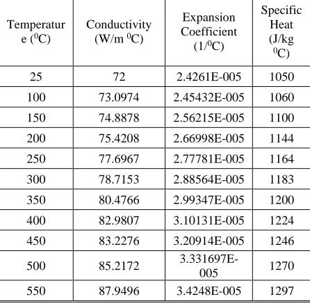
Table 5 Temperature-dependent thermal properties of AZ91
Temperatur e (0C)
Conductivity (W/m 0C)
Expansion Coefficient (1/0C)
Specific Heat (J/kg
0C)
25 72 2.4261E-005 1050
100 73.0974 2.45432E-005 1060
150 74.8878 2.56215E-005 1100
200 75.4208 2.66998E-005 1144
250 77.6967 2.77781E-005 1164
300 78.7153 2.88564E-005 1183
350 80.4766 2.99347E-005 1200
400 82.9807 3.10131E-005 1224
450 83.2276 3.20914E-005 1246
500 85.2172
3.331697E-005 1270
© 2019 IAU, Majlesi Branch
Table 6 Temperature-dependent physical and mechanical properties of AZ91
Temperature (0C) Density
(kg/m3)
Young Modulus (Pa)
25 1810.3 46120056000
100 1795 45954410000
150 1784.8 44000314000
200 1774.2 43046214000
250 1763.2 42092114000
300 1752 40138014000
350 1740.4 39183914000
400 1728.5 38229814000
450 1716.2 37275714000
500 1703.6 36321614000
550 1690.6 35367514000
4 JOHNSON-COOK ELASTIC-PLASTIC MODEL
In this paper, the Johnson-cook model has been used to identify the plastic specifications and hardening behaviour of the material. This model defines the relation between “the stress, strain, strain rate and temperature.” This model is sufficient when the material is under the intense plastic deformation. The equation (1) is used to explain this model and calculate the flow stress:
𝜎 = (𝐴 + 𝐵𝜀𝑛)[1 + 𝐶 ln (1 + 𝜀̇ 𝜀0̇)](1 −
[ 𝑇−𝑇𝑟𝑜𝑜𝑚 𝑇𝑚𝑒𝑙𝑡−𝑇𝑟𝑜𝑜𝑚]
𝑚
) (1)
“Where σ is the equivalent stress, ε is the equivalent plastic strain, ε` is the plastic strain rate, ε`0 is the
reference strain rate, T0 is the room temperature, Tmelt is
the melting temperature, A is the initial yield stress (MPa), B is the hardening modulus, n is the work-hardening exponent, C is the coefficient dependent on the strain rate and m is the thermal softening coefficient.” The Johnson-Cook constants for every material are determined using high strain rate tests “(split Hopkinson’s bar or tensile test at high temperature and strain rate).” Therefore, the Johnson-Cook model is sufficient to define the material behaviour during the friction stir processing as a process with intense plastic deformation. The Johnson-Cook constants of AZ91 are specified in “Table 7ˮ.
Table 7 The Johnson-Cook constants to define the behavior of AZ91. [25]
“Parameters Value
A 108
B 737
C 0.06180
n 0.636
m 2.551”
The Johnson-Cook fracture model is the relation between the strain rate, the effective stress, and the temperature at the time of the fracture of the work piece. The constants of the Johnson-Cook fracture model for AZ91 are identified in “Table 8ˮ. The equation (2) is used for explaining the fracture strain (𝜀𝑓):
𝜀𝑓= [𝐷
1+ 𝐷2exp(𝐷3 𝜎∗)][1 + 𝐷4ln 𝜀̇∗][1 + 𝐷5𝑇∗] (2)
Table 8 The JOHNSON-COOK constants to define the damage evolution of AZ91
Parameters D1 D2 D3 D4 D5
Value -0.068 0.451 -0.952 0.036 0.69
6 INTERACTION AND HEAT TRANSFER
The convective heat transfer was defined using the FILM CONDITION type and is dependent on temperature. The heat transfers between the work piece and the backing plate is controlled by the coefficient equal to 8500 W/m2K. The convection coefficient from
the free surfaces is h=12 W/m2K at ambient temperature
(25 0C) [26]. Furthermore, the friction coefficient is 0.4
[27].
7 MESH
© 2019 IAU, Majlesi Branch
8 ARBITRARY LAGRANGIAN-EULERIAN,
MESH-TO-MESH SOLUTION MAPPING AND MASS SCALING
The Arbitrary Lagrangian-Eulerian formulation is used to control the mesh distortion in cases with intense deformation. This method utilizes a wide range of approaches for analysing the processes, from purely Lagrangian analysis, in which the node motion corresponds to material motion, to purely Eulerian analysis, in which the nodes remain fixed in space and material flows through the elements. Typically, Arbitrary Lagrangian-Eulerian method uses the combination of these approaches [19]. Also, by scaling the masses, the stable time increment can be increased significantly. Many trials had been made for adjusting the mass scaling and obtaining suitable values for FSW. The mass scale of the target time increment in this paper is 0.0001.
7 RESULTS
During Friction Stir Processing, the stirring of material was obtained through softening, mixing, and forging actions using the rotating tool. To prevent the formation process defects during Friction Stir Processing, it is necessary to produce enough heat. In other words, the essential issue for performing FSP is generation of sufficient amount of frictional heat for softening work piece. The plastic deformation and frictional energy should supply the necessary heat for performing this process. “The frictional energy depends on the friction coefficient, the contact area between the tool and work piece, the rotational speed and the pressure applied by the tool shoulder” [18-19].
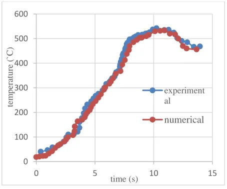
Fig. 2 The thermal/time profile to investigate the thermal changes in point with 6 mm distance from the start point.
In this section, the temperature distribution and thermal history obtained from numerical modelling have been compared with the empirical results of Parviz Asadi. The parameters defined in this model, including dimensions, material properties, the thermal and contact conditions, were the same as Parviz Asadi et al. [27]. To investigate the thermal aspects of this process, it is essential to determine the thermal history of some points and the temperature distribution during Friction Stir Processing. Thermal history was curved for the point that is in the distance 6 mm from the start point. This comparison is shown in “Fig. 2” and indicates a proper agreement between the experimental measurements and the modelling results. These results are used to investigate the microstructure characterization of the process affected zone.
Also, the temperature contours along the transverse direction are shown in “Fig. 3”. These contours are presented in the transverse direction after 10 mm tool translation. As shown in “Fig. 3”, the maximum temperature is 494ºC. Around the pin, the temperature distributes asymmetrically. The maximum temperature in the advancing side (AS) is 494ºC, while the maximum temperature in the retreating side (RS) is about 470ºC. The reason for this issue can be explained that the plastic deformation in the advancing side is more than that in the retreating side. This observation is reported with other researchers [19-20]. The dissipating of heat from the work piece to the backing plate causes the contour with the “V” shape.
Fig. 3 The temperature contours along the transverse direction after 10 mm tool translation.
As shown in “Fig. 4ˮ, in the longitudinal direction, the maximum temperature was observed in the contact region of the edge of the shoulder and the work piece. In other words, the maximum temperature was observed at the work piece/shoulder interface and behind the pin. The maximum heat generation and heat radiation dissipation occur in this region just behind the shoulder edge.
0 100 200 300 400 500 600
0 5 10 15
tem
p
era
tu
re
(`
C)
time (s)
experiment al
© 2019 IAU, Majlesi Branch
Fig. 4 The temperature contours along the longitudinal direction after 10 mm tool translation.
Figure 5 shows the temperature distribution at 15 representative time points 1.5s, 4.5s, 6.3s, 6.4s, 6.6s, 7s, 8.3s, 11.6s, and 13.5s in the first pass and “Fig. 6ˮ shows the temperature distribution at 2s, 5.3s, 6.6s, 7.3s, 7.8s, and 11s in the second pass.
Fig. 5 The temperature distributions at 1.5s, 4.5s, 6.3s, 6.4s, 6.6s, 7s, 8.3s, 11.6s and 13.5s in the first pass.
It is noteworthy that, during the first pass, plunge phase occurs from 0 to 8 s and traverse phase happens from 8 s to 18 s and during the second pass, plunge phase occurs from 19.64 to 28.64s and traverse phase occurs 28.64to 38.64s. In “Figs. 5 and 6”, in every cell, the top row picture provides the cross-section view along the progressive path, while the bottom row picture gives the view from the top. As it is seen, when only the pin was in contact with the surface of the specimen, the maximum temperature in the work piece occurred somewhere adjacent to the edge of the pin bottom surface. After 6.4 seconds, in every pass, the tool shoulder contacts the work piece; thereafter, the region with maximum temperature moved towards the corner between the pin and shoulder surface. At 7.8s in every pass, the full contact between tool and work piece was established, in this time, the maximum temperature was in the shoulder-work piece interface. A high-temperature gradient with “V” shape appeared in the work piece beneath the tool, demonstrating high heat
flux between the interface layer and the work piece’s material outside the shoulder radius.
Fig. 6 The temperature distributions at 2s, 5.3s, 6.6s, 7.3s, 7.8s and 11s in the second pass.
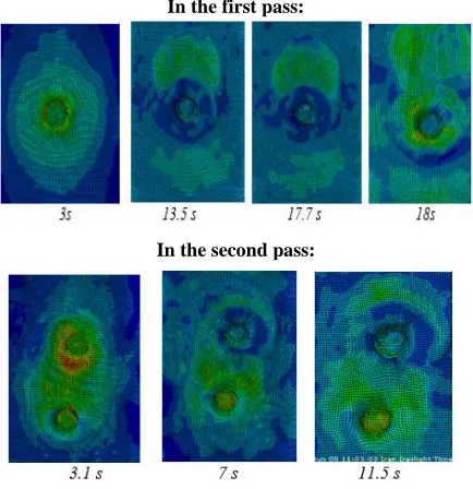
Moreover, “Fig. 7ˮ shows the residual stress distribution in the longitudinal direction at time points 3s, 13.5s, 17.7s, and 18s in the first pass and 3.1s, 7s, and 11.5 s in the second pass. It is observed that the start-position and end-position of the process have different stress distributions as compared with the mid-position of the process. At the end-position of the process, the tool during the lift-up leaves the keyhole region in a compressive stress state, as shown in “Fig. 7ˮ. As shown in “Figs. 5, 6 and 7”, the temperature and stress distributions have the asymmetric shape.
In the first pass:
In the second pass:
© 2019 IAU, Majlesi Branch
8 CONCLUSIONS
In this paper, a 3D thermo-mechanical model, has been used to study the mechanical effect of the rotating tool during stirring and the thermal influences caused by frictional contact. This model is developed to investigate the effect of FSP on the Mg-alloy. The experimental results have been used to validate the proposed model. In this research, the Jonson Cook models have been used for defining the material behaviour and the failure criterion. The following conclusions can be drawn:
1. The numerical results show that after complete contact of the shoulder and work piece, the maximum temperature is found at the work piece/shoulder interface and behind the pin.
2. It was clear that the material behaviour models have the significant effect on the results of the simulation. The determining of constants is essential for precise simulation of the process. In this paper, the material model constants were extracted from previous studies. 3. The result shows that the selection of the most suitable material models, constants, heat transfer coefficient, friction coefficient and calibrating the simulation parameters is essential for a reliable modelling of the process.
4. In this study, the model with sufficient constants can successfully investigate the thermal history, stress and temperature distributions.
5. During FSP temperature, and stress distributions around the pin are asymmetric.
6. The numerical results are shown that the maximum stress in the AS region is observed.
7. The investigations indicate that the simulation results are well-validated with the experimental results. Therefore, the FE model presented in this research can be used to study and simulate the temperature and stress field accurately during FSP on Different materials and for different and suitable conditions.
9 ACKNOWLEDGMENTS
This research was supported by Shahid Rajaee Teacher Training University, Tehran, Iran and this manuscript has not been published and is not under consideration for publication elsewhere.
REFERENCES
[1]Abaqus User Manual, Version 6.3, 2002 (Hibbitt, Karlsson & Sorensen, Pawtucket, Rhode Island).
[2]de Dear, R., Brager, G., Thermal Comfort in Naturally Ventilated Buildings: Revisions to ASHRAE Standard 55, Energy and Buildings, Vol. 34, No. 6, 2002, pp. 549–561.
[3]Tutunchilar, S., Haghpanahi, M., Besharati Givi, M. K., and et al, Simulation of Material Flow in Friction Stir Processing of a Cast Al-Si alloy, Mater Des, Vol. 40, 2012, pp. 415 -426.
[4]Rahul, J., Surjya, K., and Pal, S., Finite Element Simulation of Pin Shape Influence On Material Flow Forces in Friction Stir Welding, International Journal of Advanced Manufacturing Technology, Vol. 38, 2017, pp. 285–295.
[5]Assidi, M., Fourment, L., Guerdoux, S., and Nelson, T., Friction Model for Friction Stir Welding Process Simulation: Calibrations from Welding Experiments, International Journal of Machine Tools and Manufacture, Vol. 50, 2010, pp. 143 – 155.
[6]Chen, C., Kovacevic, R., Finite Element Modelling of Friction Stir Welding—Thermal and Thermomechanical Analysis, International Journal of Machine Tools and Manufacture, Vol. 43, 2003, pp. 1319- 1326.
[7]Schmidt, H., Hattel, J., and Wert, J., An Analytical Model for The Heat Generation in Friction Stir Welding, Modelling and Simulation in Materials Science and Engineering, Vol. 12, 2003, pp. 143.
[8]Darras, B. M., A Model to Predict the Resulting Grain Size of Friction-Stir-Processed Az31 Magnesium Alloy, Journal of Materials Engineering and Performance, Vol. 21, 2012, pp. 1243-1248.
[9]Aljoaba, S., Dillon, O., Khraisheh, M., and Jawahir, I., Modelling the Effects of Coolant Application in Friction Stir Processing On Material Microstructure Using 3d Cfd Analysis, Journal of Materials Engineering and Performance, Vol. 21, 2012, pp. 1141-1150.
[10] Yu, Z., Zhang, W., Choo, H., and Feng, Z., Transient Heat and Material Flow Modelling of Friction Stir Processing of Magnesium Alloy Using Threaded Tool, Metallurgical and Materials Transactions A, Vol. 43, 2012, pp. 724-737.
[11] Albakri, A., Mansoor, B., Nassar, H., and Khraisheh, M., Thermo-Mechanical and Metallurgical Aspects in Friction Stir Processing of Az31 Mg Alloy—A Numerical and Experimental Investigation, Journal of Materials Processing Technology, Vol. 213, 2013, pp. 279-290.
[12] Asadi, P., Mahdavinejad, R., and Tutunchilar, S., Simulation and experimental investigation of FSP of AZ91 magnesium alloy Materials Science and Engineering: A 528, 2001, pp. 6469-6477.
[13] Frigaard, Grong, and Middling, O. T., A Process Model for Friction Stir Welding of Age Hardening Aluminium Alloys, Metal Mater Trans, 2001, Vol. 32, pp. 1189–200.
[14] Khandkar, M. Z. H., Khan, J. A., Reynolds, A. P., and Sutton, M. A., Predicting Residual Thermal Stresses in Friction Stir Welded Metals, J Mater Process Technol, Vol. 174, 2006, pp. 195–203.
© 2019 IAU, Majlesi Branch 2008, pp. 769–779.
[16] Ulysse, P., Three-Dimensional Modelling of the Friction-Stir-Welding Process, International Journal of Machine Tools and Manufacture, Vol. 42, 2002, pp. 1549– 1557.
[17] Shercliff, H. R., Colegrove, P. A., Modelling of Friction Stir Welding. in: Cerjak h, Editor. Mathematical Modelling of Weld Phenomena, London: Maney, Vol. 6, 2002, pp. 927–974.
[18] Tutunchilar, S., Haghpanahi, M., Besharati Givi, M. K., Asadi, P., and Bahemmat, P., Simulation of Material Flow in Friction Stir Processing of a Cast Al-Si Alloy, Mater Des, Vol. 40, 2012, 415–426.
[19] Chiumenti, M., Cervera, M., Agelet de Saracibar, C., Dialami, N., Numerical Modelling of Friction Stir Welding Process, Computer Methods in Applied Mechanics and Engineering, Vol. 254, 2013, pp. 353–369.
[20] Dialami, N., Chiumenti, M., Cervera, M., Agelet De Saracibar, C., and Ponthot, J. P., Material Flow Visualization in Friction Stir Welding Via Particle Tracing, International Journal of Material Forming, Vol. 8, 2015, pp. 167–181.
[21] Al-Badour, F., Merah, N., Shuaib, A., and Bazoune, A., Thermomechanical Finite Element Model of Friction Stir Welding of Dissimilar Alloys, International Journal of Advanced Manufacturing Technology, Vol. 72, No. 5–8, 2014, pp. 607–617.
[22] Cao, J. Y., Wang, M., Kong, L., Yin, Y. H., and Guo, L. J., Numerical Modelling and Experimental Investigation of Material Flow in Friction Spot Welding of
Al 6061-T6, International Journal of Advanced Manufacturing Technology, Vol. 89, No. 5–8, 2017, pp. 2129–2139.
[23] Ajri, A., Shin, Y. C., Investigation on the Effects of Process Parameters On Defect Formation in Friction Stir Welded Samples Via Predictive Numerical Modelling and Experiments, Journal of Manufacturing Science and Engineering, Vol. 139, No. 11, 2017, pp. 111009.
[24] Ansari, M. A., Samanta, A., Abdi Behnagh, R., and Ding, H., An Efficient Coupled Eulerian-Lagrangian Finite Element Model, 2018.
[25] Xiao, J., Raza Ahmad, I., and D. W. Shu, Dynamic Behaviour and Constitutive Modelling of Magnesium Alloys Az91d and Az31b Under High Strain Rate Compressive Loading, Modern Physics Letters B, Vol. 28, No. 8, 2014, pp. 1450063 (9 pages).
[26] Bazhenov, V. E., Petrova, A. V., Koltygin, A. V., and Tselovalnik Yu, V., Determination of Heat Transfer Coefficient Between Az91 Magnesium Alloy Casting and No-Bake Mold, Tsvetnye Metally, 2017.
[27] Asadi, P., Besharati Givi, M., and Akbari, M., Microstructural Simulation of Friction Stir Welding Using a Cellular Automaton Method: A Microstructure Prediction of Az91 Magnesium Alloy, M. International Journal of Machine Tools and Manufacture, Vol. 10, 2015, pp. 20.
![Table 7 The Johnson-Cook constants to define the behavior of AZ91. [25]](https://thumb-us.123doks.com/thumbv2/123dok_us/8964566.1873934/4.618.70.296.111.332/table-johnson-cook-constants-define-behavior-az.webp)