IJMF, Iranian Journal of Materials Forming, Vol. 1, No. 2, pp 14-22 Printed in The Islamic Republic of Iran, 2014
© Shiraz University
The Relationship between Constant Friction Factor and Coefficient of Friction in Metal Forming Using Finite Element Analysis
SH. Molaei, M. Shahbaz, R. Ebrahimi*
Department of Materials Science and Engineering, School of Engineering, Shiraz University, Shiraz, Iran
Abstract: Frictional shear stress is usually determined by utilizing the coefficient of friction or the constant friction factor models. The present study deals with finite element analysis of double cup extrusion process to determine the relationship between constant friction factor (m) and coefficient of friction (µ), since the metal flow in this process is very sensitive to frictional conditions. Therefore, the Finite Element-Code Deform 2D is used which is capable of utilizing both µ and m. According to this analysis, a new equation between constant friction factor (m) and coefficient of friction (µ) is suggested. Moreover, in order to evaluate the suggested equation and to compare it with the previous equations, finite element analysis of barrel-compression test is carried out. Finite element results indicate that the new equation can accurately predict the relation between m and its equivalent μ value. The importance of converting these factors to each other is specially highlighted to introduce the frictional conditions in some professional and commercial finite element software.
Keywords: Metal forming, Friction coefficient, Constant friction factor, Finite element analysis
1. Introduction
Friction is one of the most important factors in metal forming processes, which has an effect on material flow behavior. Mechanical properties of product, die life, internal structure, deforming force and energy requirements are dominated by flow pattern. Beside the detrimental effects of friction such as defect creation through deformation inhomogeneity, wearing off die, etc., friction can also be used beneficially for manipulating the material flow to achieve the desired product with a minimum effort in metal forming processes such as rolling, conform-extrusion and extrusion-forging processes. Therefore, for satisfying the requirements of die design and achieving the sound components, estimation of the frictional condition and its magnitude is an important concern in all metal working processes.
The constant friction model
mk
[1, 2] and coefficient of friction
p
[1, 3] are the important friction models in metal forming analysis, specially in Finite Element Analysis (FEA), where p,k, μ and m are the normal pressure, shear yield stress, coefficient of friction and the constant friction
factor, respectively. In an attempt to obtain quantitative data on friction in metal forming processing, the number of studies has already been made based on these models, using actual metal forming operations or simulative laboratory tests [4]. Double Cup Extrusion (DCE) process [5], upset forging process [6-8] and ring test [9] are mostly used for this purpose.
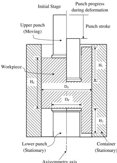
DCE process is a combination of forward and backward extrusion in which the upper punch moves downwards, while the lower punch and the container are stationary. Thus, frictional condition is different at upper and lower portions. This makes a difference between the height of extruded upper and lower cups in a manner that the ratio between these two heights is controlled by the frictional condition [10, 11]. Figure 1 shows the axisymmetric schematic of DCE test in both initial stage and punch progress during deformation.
Received by the editors April 27, 2014; Revised July 25, 2014 and Accepted July 27, 2014.
Fig. 1. Axisymmetric schematic of DCE test in both initial stage and during deformation.
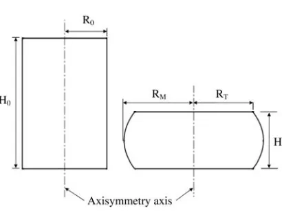
Ebrahimi and Najafizadeh developed a new method named Barrel Compression (BC) test to determine the constant friction factor, which involves only the physical measurement of the billet shape changes [12]. In other words, in BC Test there is no need for mechanical properties of the material and the forming loads, whereas the measurement of these parameters presents a major difficulty due to the cumbersome nature of the experiments, especially those at high temperatures and high strain rates. In this test, the effect of frictional condition is determined through measuring the degree of barreling, as [12]:
H H R
R b
4 (1)
where
H H R
R 0
0
T
M R
R R
and
H H
H
0
where b, H, H0, R0, RM and RT are barreling parameter, height of cylinder after deformation, initial height
SH. Molaei et al.
16
Fig. 2. 2D representation of BC test.
In addition to practical techniques, several numbers of analytical methods such as slab method, slip-line method, upper bound technique, etc., are improved for quantitative analysis of frictional condition. However, the finite element method has been regarded as the most powerful method of analysis in comparison with the above mentioned methods [14]. Development of plastic FEA assists in calculating the local stress, strain, temperature distribution and other practical parameters in metal forming processes and accuracy of the FEA depends on the input data such as material properties and tool-workpiece interface conditions. For this purpose, some professional FE-Codes such as Abaqus, Ansys, Deform, etc., were improved which operate in constant friction factor and/or coefficient of friction. On the other hand, depending on the laboratory equipment or accessories, the measurement of the friction may be based on the constant friction factor, whereas in analysis or commercial FE-Codes, it may be necessary to express the friction through the coefficient of friction. Consequently, it is important to establish a reasonable relationship between these two parameters.
A theoretical relationship between friction factor, m, and coefficient of friction, µ, was driven using slip line method, as [15]:
1 2
27 m
m
(2)By its nature,0m1, where m = 0 describes one extreme of frictionless condition and m = 1 represents
the opposite extreme named sticking friction. Similarly, based on the ring test, an approximate empirical relationship between these two parameters has been suggested as [16]:
3 2
m
(3)Equation (2) indicates that μ = 0 at m = 0 and μ leads to infinite at m = 1, whereas Eq. (3) cannot predict the latter. However, Eq. (3) has the advantages of simplicity in practical range values of friction used in metal forming processes.
In this study, a modified equation is presented in order to relate the constant friction factor and coefficient of friction using FEA of DCE process. For further evaluation of the suggested equation, FEA of BC test was carried out as well.
2. Finite element analysis (FEA)
Diameter of punch, Dp (mm) 14
Punch velocity, Vp (mm/s) 10
3. Simulation results and discussion
Previous investigations on DCE process have shown that the ratio between the height of extruded upper cup and the height of extruded lower cup (H1/H2) is very sensitive to the reduction ratio, r = Dp2/D02, in
the range of 0.25 to 0.50 [19]. In r = 0.25, friction operates at both punch-workpiece and container-workpiece interfaces in the forward extrusion, while in the backward extrusion, friction operates only at the punch-workpiece interface, since there is no relative velocity between container and billet. Hence, the ratio of the cup heights (H1/H2) increases and the sensitivity to friction enhances [10]. Therefore, in this
study the punch diameter was selected based on the r value of 0.25.
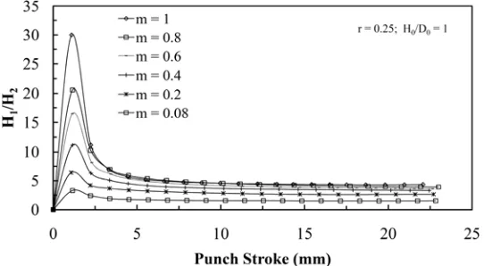
For r=0.25, the ratio of H1/H2 and punch stroke trajectory for the various amounts of constant friction
factor in the range of 0.08m1were studied using point tracking in FE-Code Deform-2D (Fig. 3). As
shown in Fig. 3, there is a similar trend for all selected m values, so that the ratio of H1/H2 after the same
punch stroke reaches constant value. A similar trend was found in a study by Buschhausen et al. [20]. The
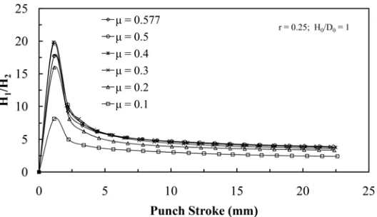
same procedure was also perceived for the various amount of coefficient of friction varying in the range of 0.1-0.577, for r = 0.25 (Fig. 4). Thus, based on the obtained results (Figs. 3 and 4) the punch stroke of 11 mm was selected for all the ongoing analysis.
Using the data in Figs. 3 and 4, with the constant punch stroke of 11mm, the effect of various m- and μ-values on the ratio of H1/H2 was investigated (Fig. 5). As seen in Fig. 5, by increasing the severity of
frictional condition, the ratio of H1/H2 also increases. A similar trend is reported by other researchers as
well [20, 21].
SH. Molaei et al.
18
Fig. 4. Variations of H1/H2 vs. punch stroke for various values of µ.
Fig. 5. Effect of m and µ on H1/H2 ratio.
Data for µ and m in the same ratio of cup heights based on the depicted results in Fig. 5 were plotted in Fig. 6. Based on the features mentioned in Eq. (2), a similar form was used as the suggested equation for the data in Fig. 6. The numerical constants of this equation were obtained using regression method, as:
0.11 9 . 01 72 .
2 m
m
(4)Fig. 6. Diagram of constant friction factor (m)-values vs. equivalent coefficient of friction (μ)-values from Eq. (4), at the same cup heights ratio.
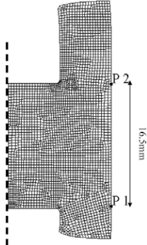
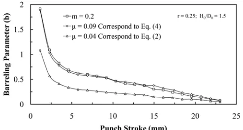
The axisymmetric simulation of DCE process in punch stroke of 11 mm is exhibited in Fig. 8. To compare the Eqs. 2 and 4 to each other the normal pressure variation between two points on die surface (P1 and P2) were studied by utilizing state variable option in FE-Code DEFORM-2D. Figure 9 displays the pressure distribution between two points of p1 and p2 by considering frictional condition of m=0.2 and μ equivalents from Eqs. 2 and 4. According to Fig. 9, the normal pressure obtained for m = 0.2 and μ =
0.09, which was calculated from Eq. (4) was more accordant than μ = 0.04, which was obtained from Eq.
(2). Therefore, this agreement confirms the accuracy of FEA data in developing new equation.
Fig. 8. Axisymmetric FEA simulation of double cup extrusion process for r = 0.25, m = 0.2 and punch stroke of 11mm.
Fig. 9. Variation of normal pressure on die surface between two points p1 and p2.
SH. Molaei et al.
20
shows the axisymmetric schematic of BC test, which was used for FEA. Using geometrical dimensions
(H, H0, R0, RM and RT) during deformation in finite element analysis, barreling parameter is calculated
from Eq. (1) for each instance. The results for barreling parameter versus punch stroke of these m- and µ-values are shown in Figs. 11 and 12. As shown in these figures, there is good agreement between the degree of barreling for frictional condition caused by m value and corresponding µ value obtained from Eq. (4), rather than Eq. (2). Consequently, it can be considered as additional evidence to confirm the accuracy of Eq. (4).
Fig. 10. Axisymmetric schematic of barrel compression test with its boundary condition used in FEA.
Fig. 11. Variation of barreling parameter vs. punch stroke in BC test.
5. References
[1] J. A. Schey, Tribology in Metalworking: Friction, Lubrication and Wear, American Society for Metals, The United States, (1983).
[2] E. Siebel, Resistance and deformation and the flow material during rolling, Stahl und Eisen, 50 (1930) 1769– 1775.
[3] Th. Von Karman, on the theory of rolling, Zeitschrift für Angewandte Mathematik und Mechanik, 5 (1925) 139– 141.
[4] X. Tan, Comparisons of friction models in bulk metal forming, Tribology International, 35 (2002) 385–393. [5] R. Geiger, Metal Flow in Combined Can Extrusion, Reports from the Institute for Forming Technology of the
University Stuttgart Nr. 36, Girardet Essen Germany, (1976).
[6] K. Manisekar and R. Narayanasamy, Phenomenon of barreling in square billets of aluminium during cold upset forging, International Journal Advanced Manufacturing Technology, 21 (2003) 84–90.
[7] S. Malayappan and R. Narayanasamy, An experimental analysis of upset forging of aluminium cylindrical billets considering the dissimilar frictional conditions at flat die surfaces, International Journal Advanced Manufacturing Technology, 23 (2004) 636–643.
[8] S. Malayappan and G. Esakkimuthu, Barreling of aluminium solid cylinders during cold upsetting with differential frictional conditions at the faces, International Journal Advanced Manufacturing Technology, 29 (2006) 41–48.
[9] M. Kunogi, Reports of the Scientific Research Institute, Tokyo, 30 (1954) 63.
[10]N. Bay, The state of the art in cold forging lubrication, Journal of Materials Processing Technology, 46 (1994) 19–40.
[11]L. Wang, J. Zhou, J. Duszczyk and L. Katgerman, Friction in aluminium extrusion—Part 1: A review of friction testing techniques for aluminium extrusion, Tribology International, 56 (2012) 89–98.
[12]R. Ebrahimi and A. Najafizadeh, A new method for evaluation of friction in bulk metal forming, Journal of Materials Processing Technology, 152 (2004) 136–143.
[13]K. Manisekar and R. Narayanasamy, Effect of friction on barreling in square and rectangular billets of aluminum during cold upset forging, Materials & Design, 28 (2007) 592–598.
[14]Sh. Koayashi, Soo-IK Oh and T. Altan, Metal Forming and the Finite-Element Method, Oxford Series on Advanced Manufacturing, (1989).
[15]N. Bay, Friction stress and normal stress in bulk metal forming processes, Journal of Mechanical Working Technology, 14 (1987) 203–223.
[16]K. P. Rao and K. Sivaram, A review of ring-compression testing and applicability of the calibration curves, Journal of Materials Processing Technology, 37 (1993) 295–318.
SH. Molaei et al.
22
[18]N. Pardis and R. Ebrahimi, Deformation behavior in simple shear extrusion (SSE) as a new severe plastic deformation technique, Materials Science and Engineering A, 527 (2009) 355–360.
[19]M. L. Ghobrial, J. Y. Lee, T. Altan, N. Bay and B. G. Hansen, Factors affecting the double cup extrusion test for evaluation of friction in cold and warm forging, CIRP Annals - Manufacturing Technology, 42 (1993) 347-351. [20]A. Buschhausen, K. Weinmann, J. Y. Lee and T. Altan, Evaluation of lubrication and friction in cold forging
using a double backward extrusion process, Journal of Materials Processing Technology, 33 (1992) 95–108. [21] T. Schrader, M. Shirgaokar and T. Altan, A critical evaluation of the double cup extrusion test for selection of