Linear Numerical Stress Analysis of Concrete Specimens
under Different Direct Tension Test Setups
H. Dabbagh
∗, A. Nosoudi, H. Mohammad Doost
Civil Engineering Department, Kurdistan University, Sanandaj, Iran.
Article info
Article history:
Received 2016.11.25 Received in revised form 2017.01.08
Accepted 2017.02.19
Keywords:
Direct tension Tensile strength
Tensile stress distribution Finite element analysis ABAQUS
Abstract
Tensile strength is one of the basic and important mechanical properties of concrete. The measurement of the tensile strength of concrete is not easy. This is because this property of concrete is dependent on the different test setups that must be used. Indirect methods have been used hitherto to measure tensile strength of concrete. These methods though widely accepted, do not provide the true tensile strength of concrete in comparison with direct methods. According to this, the present study focuses on the analytical and experimental investigation of the prismatic concrete specimens under direct tension test setups. In this paper, different test setups were studied to produce a more uniform tensile stress distribution and minimize stress concentration at both ends of the concrete specimens with normal compressive strength. ABAQUS software was employed to carry out the fi-nite element analysis of the concrete specimens under direct tension test setups.
1. Introduction
Investigation in the tensile properties of concrete has considerably increased in recent years. This is because tensile strength of concrete represents an important characteristic for the design and analysis of concrete structures. According to this,the study of the tensile properties of concrete, both experimentally and numer-ically was developed by many researchers [1-10]. In or-der to determine the tensile strength of concrete, test-ing methods can be classified as (a) direct methods, and (b) indirect methods. The indirect tension test methods are widely used for studying the tensile prop-erties of concrete due to their simplicity. The flexural strength test and splitting tensile strength test which include indirect testing methods can be conducted in accordance with the American Standard Test Method, ASTM C78 and ASTM C293 [11,12] and ASTM C496 [13], respectively. Flexural testing is used for determin-ing the flexural strength of concrete by two different methods. Such tests are conducted by applying a cen-tral load (ASTM C78) or with two load points (ASTM
C293) on the thirds of the support span of the prismatic concrete specimens. Rocco et al. [14] analyzed the ef-fect of specimen size and load bearing strip width on the determined splitting tensile strength in this test; it was found that the splitting tensile strength decreases with increase inspecimen size. On the other hand, wider load bearing strips lead to an increase of the value of the splitting tensile strength. Subsequently, the experimental investigations were analyzed numer-ically using the Fictitious Crack Model implemented in a FE-code [15]. The calculations showed the same result as the experimental tests represented.
These indirect methods though widely accepted, do not provide the true tensile strength of concrete. This means that these test methods give the higher value of tensile strength than the uniaxial tensile strength but the direct tension test provides results which are more reliable [16-18]. Swaddiwudhipong et al. [19] de-termined the tensile strain capacity of concrete from direct tension test. Seven mixes of concrete were de-signed to study the effects of age, compressive strength, and mineral admixture on the tensile strain capacity; ∗Corresponding author: H. Dabbagh (Associate Professor)
E-mail address: [email protected]
it was shown that the tensile strain capacity of con-crete was a relatively independent parameter. Alhus-sainy et al. [20] proposed a new procedure to de-termine the stress-strain behaviorof Self-Compacting Concrete (SCC) under direct uniaxial tension. Special steel claws were designed, built and installed at both ends of SCC specimens. The test results showed that there was no slippage or fracture at the ends of any of the specimens. Wu et al. [21] performed a new experi-mental method for testing the dynamic tensile behav-ior of concrete at high strain rates. The experimen-tal results indicated that the dynamic tensile strength of concrete was rate sensitive. Lu and Li [22] exam-ined experimental methods for determining the tensile strength of concrete-like materials over a wide range of strain-rates. A micro-mechanism model was developed to demonstrate that micro-crack inertia was one of the mechanisms responses for the increase of dynamic ten-sile strength with strain-rate observed in the dynamic tensile tests on concrete-like materials.
Fahimifar and Malekpour [23] used the direct ten-sion test apparatus and a servo-control testing ma-chine to determine the direct tensile strength of the rock specimens. A finite element analysis was con-ducte dusing ABAQUS software to investigate the ef-fect of both length-to-diameter ratio (geometrical ra-tio) and the boundary condition on the Brazilian test results. The results showed that the splitting tensile strength measured in the Brazilian test decreases with increasing geometrical ratio. Several methods have been proposed for direct tension test, such as using friction grip and epoxy, to attach the loading machine and concrete specimen. Gonnerman and Shuman [24] conducted direct tension tests of concrete cylinders us-ing bolted steel strap grips with friction surfaces to hold and pull the ends of the specimen. Saito [25] and Gopalaratnam and Shah [26] performed direct sion tests for prismatic concrete specimens with ten-sile loads using the friction grip at the ends of the samples. Nianxiang and Wenyan [27] did another di-rect tension test method, which applies tension load through embedded steel studs in concrete at the both ends of the specimens. All these above methods rep-resent a non-uniform stress distribution for concrete specimens as shown in Fig. 1a and 1b. This is be-cause that secondary stress is induced at the ends of the concrete specimens. Accordingly, Phillips and Bin-sheng [28] presented an experimental investigation on the enlarged concrete specimens using friction grip to avoid end effect, but the tensile stresses developed in the specimen are not uniformly distributed, even in the same cross-section, as displayed in Fig. 1c. However, to produce a more uniform tensile stress distribution at the ends of the concrete specimens, the most reli-able method under pure uniaxial tension is required to be tested. Because of this reason, RILEM and the U.S. Bureau of Reclamation [29,30] presented other
di-rect tension test setups for concrete specimens. One of these direct tension test methods is to use a single glued steel end plate which is centrally pulled at both ends of the specimen as depicted in Fig. 2a [16,29]. Furthermore, RILEM [29] recommended the testing method for direct tension of cylindrical specimens as well as prismatic specimens without any details about dimensions of the specimen and the end plates. In ad-dition to these referred methods, the U.S. Bureau of Reclamation [30] recommends the use of double glued steel plates at both ends of the specimen. The outer plate is connected to a loading machine and the inner plate is bonded with the concrete specimen with epoxy, while the outer plate is connected to the inner plate by a number of bolts showing acceptable results as illus-trated in Fig. 2b. In view of this literature review,the present study focuses on the analytical and experimen-tal investigation of the prismatic concrete specimens under direct tension test setups.
Fig. 1. Stress distribution at both ends of the concrete specimens under direct tension test: (a) with friction grips at both ends [25,26], (b) with studs embedded in concrete at both ends [27], (c) with friction grips and enlarged ends [28].
men-tioned in the previous explanations. A pilot investi-gation was conducted on a small scale with the num-ber of 16 prismatic concrete specimens. Experimental investigation was carried out based on the most reli-able test setup with uniform stress distribution results under pure uniaxial tension. This study mostly con-centrates on specific objectives, including determining suitable test setup from different tests introduced and an examination of different thickness of the outer plate as well as inner plate of the concrete specimens which are carried out based on this direct test to provide a more uniform tensile stress distribution.
Fig. 2. Stress distribution at both ends of the concrete specimens under direct tension test: (a) with single glued steel plates at both ends [16,29], (b) with double glued steel plates and a number of bolts in concrete at both ends [30].
2. Research Significance
The major difficulty in conducting direct tensile tests on the prismatic concrete specimens is to achieve a uniform tensile stress across a section of the concrete without inducing secondary stresses. This means that the direct tensile test setup creates stress concentra-tion at the ends of the concrete specimens that cannot be ignored on the results interpretation. The primary significance of this study is to determine the most reli-able direct tension test among the existing test setups based on finite element analysis results.
3. Finite Element Analysis
Three-dimensional finite element analysis was con-ducted with ABAQUS [31] software. Different direct tension test setups were considered as proposed by oth-ers [25-30] illustrated in Figs. 1 and 2. The concrete specimens were assigned a linear elastic property prior
to analysis. A 25.7 kN tension load was applied gradu-ally to the prismatic concrete specimens. According to the low tensile loading, the ranges of stress within steel as well as concrete were in elastic zone. So, because of this reason linear finite element analysis was performed to investigate the stress distribution along the square concrete specimens among different direct tension test setups, as mentioned previously [25-30]. The loading and boundary conditions were applied in a way that is similar to the actual test setup [25-30]. Regarding to the symmetry of the specimens and loading, an upper half of the specimens length were modeled. The finite element mesh used for all these methods are shown in Figs. 3 and 4. An eight-node 3-D solid element (C3D8R) was used to model the steel and the concrete. The epoxy adhesive was simulated by an eight-node 3-D cohesive element (COH33-D8).
Fig. 3. Finite element mesh for stress distribution analysis of the concrete specimens: (a) with friction grips, (b) with studs embedded in concrete, (c) en-larged end specimen with friction grips.
Details of the material properties of concrete spec-imens used for linear elastic finite element analysis are summarized in Table 1.
Table 1
The material properties of concrete specimens.
Materials Modulus of elasticity (MPa)
Poissons ratio
Concrete (C30)
27400 0.2
Steel 200000 0.3
Epoxy 1000 0.3
4. Results of the Finite Element
Analy-sis
The tensile stress distribution of the linear FE analy-sis at the end interface of the concrete specimen (A-A cross-section as depicted in Figs. 1 and 2) for all these proposed direct tension methods as noted previously, are shown below, see Figs. 5-9.
Fig. 5. The tensile stress distribution at the end in-terface of the concrete specimen with friction grips.
Fig. 6. The tensile stress distribution at the end in-terface of the concrete specimen with studs embedded in concrete.
Fig. 7. The tensile stress distribution at the end in-terface of the concrete specimen with friction grips and enlarged end.
Fig. 8. The tensile stress distribution at the end in-terface of the concrete specimen with single glued steel plates.
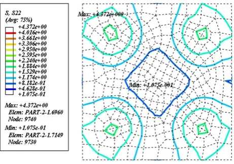
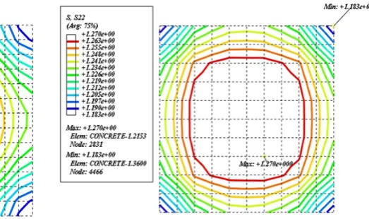
Fig. 9. The tensile stress distribution at the end inter-face of the concrete specimen with double glued steel plates and a number of bolts.
1 and 2) for prismatic concrete specimen using friction grips at the ends, the tensile stress varies from 0.5813 to 2.611MPa and the variation of stress distribution over the entire sectional area is within±175% of the average tensile stress for this test [25-26]. For concrete speci-men with steelstuds, the tensile stresses among steel studs and also end edge of these studs which were em-bedded in concrete vary from 0.1075 to 1.174MPa and 1.174 to 4.372MP are spectively. This means that the variations of stress distribution over the entire sectional area are within±496% and±136% of the average ten-sile stress for this testing method [27] as mentioned previously. From the results, it is obvious that these direct tension methods represent a non-uniform stress distribution for concrete specimens. Also for enlarged end specimen with friction grips the tensile stress varies from 1.837 to 2.006MPa and the variation of stress dis-tribution over the entire sectional area is within ±5% of the average tensile stress for this testing method [28] as noted previously.
Furthermore, for the numerical results of the spec-imen with single glued steel plates the tensile stress across the section varies from 1.038 to 1.494MPa and also for specimen using double glued steel plates with a number of bolts, the tensile stress across the section varies from 1.128 to 1.285MPa as seen in Figs. 8 and 9. According to these results, the variations of stress distribution over the entire sectional area are within ±22% and ±7% of the average tensile stress for these testing methods [16,29-30] that were mentioned respec-tively. From these linear FE analysis results, it is obvi-ous that the enlarged end specimen with friction grips and concrete specimen using double glued steel plates with a number of bolts have the minimum variation of stress distribution over the entire sectional area under pure uniaxial tension. According to insignificant dif-ference in stress distribution variation between these direct tensile tests and due to the simplicity of pris-matic concrete specimen manufacturing, it can be con-cluded that the concrete specimen using double glued steel plates with a number of bolts is the most reliable method under pure uniaxial tension that represents a more uniform tensile stress distribution at both ends of the concrete specimens, as displayed in Fig. 9.
5. Experimental Implementation
According to the determination of the suitable test setup from different proposed methods based on the numerical results of the linear FE analysis for the tensile stress distribution as noted previously,a dou-ble plate system with epoxy adhesive which the inner and outer plates were connected to each other by eight number of bolts, was adopted for the direct tension test setup as shown in Figs. 10-12. Experimental tests were performed at the Concrete Research Laboratory
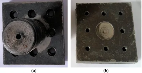
of the University of Kurdistan. In the present pilot study, this modified direct tension test setup was used for prismatic concrete specimens with the square cross-section of 100×100×360mm. The double end plates assembly at each ends of the specimen. The inner plate has the same sectional size as the specimen and a thick-ness of 30mm whereas the outer plate consists of a 100×100×15mm square plate and a 25mm diameter pulling rod attached to the center of the plate. The inner plate was glued to the specimen end while the outer plate was connected to the inner plate by eight M8 bolts. Tension load was applied to the pulling rod of the outer plate and transmitted to the inner plate through the bolts. The epoxy adhesive used was con-trolled to be approximately 1.0mm thick. After the time needed for the epoxy to develop full strength was passed, the outer plates were bolted to the inner plates. The mix proportion of these concrete specimens for the related experiment is shown in Table 2. For the main testing program, one batch of concrete mixtures was cast for testing. The compressive strength of the tested concrete specimens at the age of 28 days ranged from 29.2 to 31.33MPa.
Fig. 10. Steel plates used in the direct tension test setup: (a) outer steel plate, (b) inner steel plate.
Table 2
Mix proportion of concrete specimens.
Cement content (kg/m3)
Water-to-cement ratio
Fine-to-total aggregates ratio
Total amount of aggregates (kg/m3)
Water-reducing admixtures (%)
465 0.31 0.48 1122 0.3
Fig. 12. Setup for direct tension test.
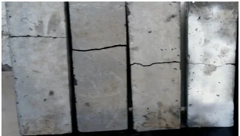
Fig. 13. Prismatic concrete specimens tested.
6. Test Results on Fracture Location
To consider the influence of fracture location on mea-sured direct tensile strength, after each direct tension test, the fracture location of the tested specimen was marked and recorded as the distance of the fracture surface from the lower end of the specimen. The ten-sile strength of the tested concrete specimens ranged from 2.57 to 3.74MPa. The direct tensile strength was normalized to the average tensile strength of theseconcrete specimens. The normalized direct tensile strength versus fracture location using pilot testing re-sults is shown below, see Fig. 14.
Fig. 14. Influence of Fracture Location on Measured Direct Tensile Strength.
As seen in Fig. 14, the normalized fracture loca-tion is distributed approximately from 0.4 to 0.8 along the length of the specimen. This experimental result, which is based on fracture location, shows that the cracking location is mostly concentrated at the top half of the vertically tested prismatic concrete specimens with square sections because of the weight effect of the concrete specimens. Otherwise, in the cases where the specimen weight is ignored such as horizontally tested concrete specimens, the fracture location in the direct tension test is expected to be uniformly distributed along the specimen. This means that cracking can oc-cur at any location along the specimen. Furthermore, according to the normalized fracture location variation from 0.4 to 0.8, the normalized direct tensile strengths are very close to 1.0. From these results, it can be con-cluded that the fracture location has little effect on the measured tensile strength of concrete specimens.
7. Parametric Studies Based on Finite
Element Analysis
Addition-ally, this parametric study based on finite element anal-ysis investigated the optimal thickness of the outer as well as the inner steel plates of the concrete specimens. According to this, eight different levels for thicknesses of both outer and inner platesof the prismatic concrete specimens were considered.
7.1. Effect of Outer Steel Plate Thickness
To evaluate the effect of outer steel plate thickness on the uniformity of stress distribution of the prismatic specimens under this modified direct tension test, the finite element analysis was performed for eight levels. Ranges of the outer steel plate thickness were consid-ered from 10 to 45mm. The analysis results of the pris-matic concrete specimens that were utilized to study the effect of different outer steel plate thicknesses are displayed in Figs. 15-23.
Fig. 15. The tensile stress distribution at the end in-terface of the concrete specimen with outer steel plate thickness of 10mm.
Fig. 16. The tensile stress distribution at the end in-terface of the concrete specimen with outer steel plate thickness of 15mm.
Fig. 17. The tensile stress distribution at the end in-terface of the concrete specimen with outer steel plate thickness of 20mm.
Fig. 18. The tensile stress distribution at the end in-terface of the concrete specimen with outer steel plate thickness of 25mm.
Fig. 20. The tensile stress distribution at the end in-terface of the concrete specimen with outer steel plate thickness of 35mm.
Fig. 21. The tensile stress distribution at the end in-terface of the concrete specimen with outer steel plate thickness of 40mm.
Fig. 22. The tensile stress distribution at the end in-terface of the concrete specimen with outer steel plate thickness of 45mm.
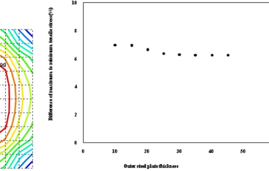
Fig. 23. Effect of outer steel plate thickness on the uniformity of stress distribution of the prismatic con-crete specimens.
According to above numerical results for the ten-sile stress distribution as shown in Figs. 15-23, it can be concluded that increased outer steel plate thickness caused decreased variations of stress distributions. It is obvious that the outer steel plate thickness has not sig-nificant effect on the uniformity of stress distribution of the prismatic specimens using double glued steel plates with a number of bolts under direct tension test setup in comparison with the inner steel plate thickness. In addition to these results, at the end interface of the specimens (A-A cross-section as depicted in Figs. 1 and 2) with double glued steel plates, the increase of outer plate thickness from 10 to 45mm, generated the variation of stress distribution over the entire sectional area from about ±7% to ±6% of the average tensile stress for this testing method that was mentioned re-spectively.
7.2. Effect of Inner Steel Plate Thickness
As noted previously, eight different levels for thick-nesses were used to demonstrate the effect of inner steel
plate thickness on the uniformity of stress distribution of the prismatic specimens.
Fig. 24. The tensile stress distribution at the end in-terface of the concrete specimen with inner steel plate thickness of 10mm.
45mm. The finite element analysis results of the pris-matic concrete specimens that were used to study the effect of different inner steel plate thicknesses are de-picted in Figs. 24-32.
Fig. 25. The tensile stress distribution at the end in-terface of the concrete specimen with inner steel plate thickness of 15mm.
Fig. 26. The tensile stress distribution at the end in-terface of the concrete specimen with inner steel plate thickness of 20mm.
Fig. 27. The tensile stress distribution at the end in-terface of the concrete specimen with inner steel plate thickness of 25mm.
Fig. 28. The tensile stress distribution at the end in-terface of the concrete specimen with inner steel plate thickness of 30mm.
Fig. 29. The tensile stress distribution at the end in-terface of the concrete specimen with inner steel plate thickness of 35mm.
Fig. 31. The tensile stress distribution at the end in-terface of the concrete specimen with inner steel plate thickness of 45mm.
Fig. 32. Effect of inner steel plate thickness on the uniformity of stress distribution of the prismatic con-crete specimens.
Considering above, from the finite element analy-sis results for the tensile stress distribution as shown in Figs. 24-32, it can be evaluated that increased in-ner steel plate thickness caused decreased variation of stress distribution. The inner steel plate thickness has significant effect on the uniformity of stress distribu-tion of the prismatic specimens using double glued steel plates with a number of bolts in comparison with the outer steel plate thickness. In addition to these results, at the end interface of the specimens (A-A cross-section as depicted in Figs. 1 and 2) with double glued steel plates, the increase of inner plate thickness from 10 to 45mm, generated the variation of stress distribution over the entire sectional area from about±8% to±3% of the average tensile stress for this testing method that was mentioned respectively.
8. Conclusions
In this paper, the linear elastic finite element analy-sis was conducted on the prismatic concrete specimens under different direct tension test setups. According to this, a pilot investigation was carried out based on the most reliable test setup under pure uniaxial tension which finite element analysis showed an acceptable re-sult of uniform stress distribution. In the present study, the influence of different thicknesses of the outer plate as well as inner plate of the concrete specimens were considered to provide a more uniform tensile stress dis-tribution. The following conclusions can be drawn from this study:
1. Direct tension tests of the prismatic concrete specimens with friction grips and steel studs embedded in concrete; represent a non-uniform stress distribution for concrete specimens.
2. Direct tension test of the concrete specimen using double glued steel plates with a number of bolts is the most reliable method under pure uniaxial tension that represents a more uniform tensile stress distribution at both ends of the specimens.
3. The cracking location is mostly concentrated at the top half of the vertically tested prismatic con-crete specimens with square sections because of the weight effect of the concrete specimens under pure uniaxial tension.
4. For concrete specimens using double glued steel plates with a number of bolts, while the thick-nesses of both outer and inner steel plates are in-creased, the variations of stress distributions are decreased.
5. The outer steel plate thickness has not significant effect on the uniformity of stress distribution of the prismatic specimens using double glued steel plates with a number of bolts under direct ten-sion test in comparison with the inner steel plate thickness.
6. The inner steel plate thickness has significant ef-fect on the uniformity of stress distribution of the prismatic specimens using double glued steel plates with a number of bolts under direct ten-sion test in comparison with the outer steel plate thickness.
Acknowledgements
References
[1] J.M. Raphael, Tensile strength of concrete, Aci. J., 81(2) (1984) 158-165.
[2] M.P. Luong, Tensile and shear strengths of con-crete and rock, Eng. Fract. Mech., 35(1-3) (1990) 127-135.
[3] C. Rocco, G.V. Guinea, J. Planas, M. Elices, Re-view of the splitting-test standards from a fracture mechanics point of view, Cement. Concrete. Res., 31(1) (2001) 73-82.
[4] H. Schuler, C. Mayrhofer, K. Thoma, Spall exper-iments for the measurement of the tensile strength and fracture energy of concrete at high strain rates, Int. J. Impact. Eng., 32(10) (2006) 1635-1650.
[5] D. Yan, G. Lin, Dynamic properties of concrete in direct tension, Cement. Concrete. Res., 36(7) (2006) 1371-1378.
[6] R.S. Olivito, F.A. Zuccarello, An experimental study on the tensile strength of steel fiber reinforced concrete. Compos. Part. B-Eng., 41(3) (2010) 246-255.
[7] Y. Tian, S. Shi, K. Jia, S. Hu, Mechanical and dy-namic properties of high strength concrete modified with lightweight aggregates presaturated polymer emulsion. Const. Build. Mater., 93 (2015) 1151-1156.
[8] M.W. Ibrahim, A.F. Hamzah, N. Jamaluddin, P.J. Ramadhansyah, A.M. Fadzil, Split tensile strength on self-compacting concrete containing coal bottom ash. Proc. Soc. Behv., 195 (2015) 2280-2289.
[9] R.V. Silva, J. De-Brito, R.K. Dhir, Tensile strength behaviour of recycled aggregate concrete. Const. Build. Mater., 83 (2015) 108-118.
[10] N.N. Gerges, C.A. Issa, S. Fawaz, Effect of con-struction joints on the splitting tensile strength of concrete. Case Studies in Construction Materials, 3 (2015) 83-91.
[11] ASTM, Standard test method for flexural strength of concrete (using simple beam with third-point loading), Am. Soc. Test. Mater. C., (2002) 78-102.
[12] ASTM, Standard test method for flexural strength of concrete (Using sample beam with center-point loading), Annual book of ASTM standards, Am. Soc. Test. Mater. C., (2003) 293-302.
[13] ASTM, Standard Test Method for Splitting Ten-sile Strength of Cylindrical Concrete Specimens, C. (2004) 496/C 496M-04.
[14] C. Rocco, G.V. Guinea, J. Planas, M. Elices, Size effect and boundary conditions in the Brazil-ian test: experimental verification. Mater. Struct., 32(3) (1999) 210-217.
[15] C. Rocco, G.V. Guinea, J. Planas, M. Elices, Size effect and boundary conditions in the Brazil-ian test: theoretical analysis. Mater. Struct., 32(6) (1999) 437-444.
[16] W. Zheng, A.KH. Kwan, P.K.K. Lee, Direct ten-sion test of concrete, Materials, 98(1) (2001) 63-71.
[17] V. Kadlecek, Z. Spetla, Direct tensile strength of concrete, Materials, 2(4) (1967) 749-767.
[18] F. Min, Z. Yao, T. Jiang, Experimental and Nu-merical Study on Tensile Strength of Concrete un-der Different Strain Rates. Scientific. World. J., 2014 (2014) 11173531.
[19] S. Swaddiwudhipong, H.R. Lu, T.H. Wee, Direct tension test and tensile strain capacity of concrete at early age. Cement. Concrete. Res., 33(12) (2003) 2077-2084.
[20] F. Alhussainy, H.A. Hasan, S. Rogic, M.N. Sheikh, M.N. Hadi, Direct tensile testing of self-compacting concrete, Const. Build. Mater., 112 (2016) 903-906.
[21] H. Wu, Q. Zhang, F. Huang, Q. Jin, Experimental and numerical investigation on the dynamic tensile strength of concrete, Int. J. Impact. Eng., 32(1) (2005) 605-617.
[22] Y.B. Lu, Q.M. Li, About the dynamic uniaxial tensile strength of concrete-like materials, Int. J. Impact. Eng., 38(4) (2011) 171-180.
[23] A. Fahimifar, M. Malekpour, Experimental and numerical analysis of indirect and direct tensile strength using fracture mechanics concepts, B. Eng. Geol. Environ., 71(2) (2012) 269-283.
[24] H.F. Gonnerman, E.C. Shuman, Compression, flexure and tension tests of plain concrete, Aci. J., 28(2) (1928) 527-564.
[25] M. Saito, Direct tensile fatigue of concrete by the use of friction grips, Aci. J., 80(5) (1983) 431-438.
[26] V.S. Gopalaratnam, S.P. Shah, Softening response of plain concrete in direct tension, Aci. J., 82(3) (1985) 310-323.
[27] X. Nianxiang, L. Wenyan, Determining tensile properties of mass concrete by direct tensile test, Materials, 86(3) (1989) 214-219.
[29] RILEM TC, Direct Tension of Concrete Speci-mens 1975 TC14-CPC, RILEM Technical Recom-mendations for the Testing and Use of Construction Materials, (1994) 23-24.
[30] U.S. Bureau of Reclamation, Procedure for Direct Tensile Strength, Static Modulus of Elasticity, and
Poissons Ratio of Cylindrical Concrete Specimens in Tension (USBR 4914-92) Concrete Manual, Part 2, 9th Edition, U.S. Bureau of Reclamation, Den-ver, (1992) 726-731.
![Fig. 1. Stress distribution at both ends of the concretespecimens under direct tension test: (a) with frictiongrips at both ends [25,26], (b) with studs embedded inconcrete at both ends [27], (c) with friction grips andenlarged ends [28].](https://thumb-us.123doks.com/thumbv2/123dok_us/8955211.1864579/2.595.296.528.328.556/distribution-concretespecimens-tension-frictiongrips-embedded-inconcrete-friction-andenlarged.webp)
![Fig. 2. Stress distribution at both ends of the concretespecimens under direct tension test: (a) with singleglued steel plates at both ends [16,29], (b) with doubleglued steel plates and a number of bolts in concrete atboth ends [30].](https://thumb-us.123doks.com/thumbv2/123dok_us/8955211.1864579/3.595.103.265.240.443/stress-distribution-concretespecimens-tension-singleglued-plates-doubleglued-concrete.webp)