110
Copyright © 2017. Vandana Publications. All Rights Reserved.
Volume-7, Issue-6, November-December 2017
International Journal of Engineering and Management Research
Page Number: 110-114
Design and Simulation of Electrothermally Actuated Silicon
Microgripper
Ayesha Parveen1, Chandan Kumar Roy2
1,2Assistant Professor, Department of ECE, Malla Reddy College of Engineering, Hyderabad, TS, INDIA
ABSTRACT
Microgrippers find their importance in the field micro assembly and nano assembly in semiconductor electronics. The crucial features to be examined throughout the design of the microgrippers are large displacement, low temperature and low power. By increasing the length of cold arm, extended arm and the flexure, the displacement of the device can be surpassed. A microgripper based on Electro-Thermal Actuators (ETA) that can produce larger displacement is presented. This microgripper is of open
type in which arms have an initial open gap of 14µm. The maximum displacement of each arm is 64µm for the applied voltage of 24V. COMSOL MULTIPHYSICS v4.3b Software is used as a simulation tool. This design of microgripper is utilized for the movement of optical components and for driving gears of motors.
Keywords-- ETA, Microgrippers, COMSOL
MULTIPHYSICS, Stress, Displacement, Temperature
I.
INTRODUCTION
The evolution of miniaturization technology has pronounced the development of compact micro tools. Thethree major considerations for makingmicrotools are: (1) Design the device in shape and size
(2) The device material and mechanical properties (3) Actuation mechanisms of the device
The microgrippers are utilized for a variety of applications, such as in security and defense, medicine, remote surveillance, and distributed networks [1]. Microgrippers with a controlled grasping force and accuracy are in demand[10].Also, the microgripper be obliged for large opening displacement at low temperature and low-power consumption.
The microgripper can be governed by either electro-static or electro-thermal actuation. Thermal actuator provides larger forces and is also easier to control in contrast to the electro-static actuator.Electro-thermal microactuators are a promising solution for large and linear displacement, lowpowerMEMS actuators. Hence, ETA is the best driving mechanism for micro grippers. Due to the presence of temperature at the gripper points, it is not suitable to use electro-thermal actuator for the biological applications. The electro-thermal actuator is also called as a “Heatuator” [3]. ETA
takes an advantage of its shape to create “bi-metallic” effect by the use of a single material.
The electro-static actuation based microgrippers, that can pick and place nano wires are demonstrated[5]. Microgrippersare made with different materials, such as polymer[7, 9] ceramic[11], nickel[4] and with different geometries. Microgrippers with chevron-type structures using nickel material have been reported[4]. The closed microcages, with highly compressively stressed diamond such as carbon and an electroplated Ni bimorph structure have been reported[4, 11]. The actuation range and piezoresistive sensitivity of an ETA microgripper established on a three-beam actuator/sensor structure using gold have been reported[8].
The electro thermally actuated silicon microgripper have not been reported much. In this paper, we proposed a microgripper based on electro-thermal actuators with silicon as a material that is highly reliable at elevated temperatures. The proposed microgripper achieves the maximum displacement of 64µmwhen the applied voltage is 24V.We discuss, the performances of ETA-based silicon microgripper, which is extremely well grounded at higher/elevated temperatures (>1414°C).
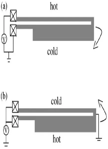
The clue to obtain higher deflection is to increasethe length of extended armsand cold arms. The basic structure of an ETA is shown in Figure 1(a). The ETA consists of a thin long arm (called a hot arm) and a
111
Copyright © 2017. Vandana Publications. All Rights Reserved.
from one electrode to the other. The thin arm gets hotterquickly (higher current density), as the resistance of the thin arm is greater than the resistance of the broad arm. Therefore, the thin arm will bend towards the broad arm to achieve thermo-elastic equilibrium as shown in Figure 1(a). The device with the two arms connected in parallel is shown in Figure 1(b). When the device is connected in parallel, the broad arm will bend towards the narrow arm as the resistance of the broad arm, in this case is smaller and draws more current.
Figure 1 (a) Series arrangement of basic electro- thermal actuator; (b) parallel arrangement
II.
PROPOSED SYSEM
2.1 Device Design
Wecan achieve maximum displacementof the basic ETA by extending the arms, with lateral movement
and the structure as shown in Figure 2. The total length of the device is taken as 1020μm from the anchors. When the device is connected in series, the resistance of the broad arm is in a series with resistance of the thin arm (the resistance of the thin arm is more than the resistance of the broad arm). Hence, the current in the structure is decided by the resistance of the thin arm. Consequently, a thinner hot arm leads to lower current and, hence, requires lower power for the same applied voltage. Also, the deflection force will be lowerif the gap between the two arms i.e. the hot and cold arm is larger. Therefore, smaller the gap and narrower beams are, deflection force will be larger [9]. Hence, in our design, we have selected the values as follows: the widths of the flexures and hot arms are 10μm, and the gap between the arms, i.e. hot and cold arm is 12μm. Total length of the device is 1020μm from the anchors, the widths of the flexures and hot arms are 10μm. The device is designed with a hot arm length of 420μm, a cold arm length of 420μm, and the flexure of 100μm, spacing between the hot arms (extended arms) is 14μm and the length of the extended arm is 600μm.
Figure 2: Structure of the proposed ETA microgripper with dimensions
Table 1 Material Properties of Silicon
PROPERTIES VALUE
Young’s modulus 170 Gpa
Thermal conductivity 130 W∕Mk
Poisson’s ratio 0.28
Electrical resistivity 1.82 × 10⁻⁴ Ωm Heat capacity at constant
pressure
700 J∕kgK
Coefficient of thermal expansion
2.6 × 10⁻⁶∕K
2.2 Finite Element Simulation
The performance of the ETA-based
112
Copyright © 2017. Vandana Publications. All Rights Reserved.
profiles on the hot arm and the stress at the flexures andconnectors for various voltages.
The boundary conditions are utilized such thatthe ends of theactuators at the anchors are mechanically fixed, and all other boundaries are free to move for the lateral movement. The DC voltage is selectively applied at the ends of the arm of the actuator. Resistivity of the material is temperature dependentand is given by the following equation:
ρ= ρ0 [1+αR(T-T0)] (1) where
ρ0 is the resistivity at a reference temperature, αRis the temperature coefficient of resistivity, T0 is the reference temperature.
The heat diffusion equation is given by
∇2T+q/k=1/α(∂T/ ∂t) (2) where
α is the thermal diffusivity T is the temperature distribution
k is the thermal conductivity of the material ρ is the density
c is the specific heat capacity q is the volumetric heat loss
The heat transfer due to convection (and/or conduction) as a function of temperature is given by q (t) = h ( T-T0 ) (3)
where
h is the heat transfer coefficient of the material T is the temperature distribution
T0 is the reference temperature.
2.3 Performance Measures
In order to analyze the behavior of the above structure using COMSOL MULTIPHYSICS, we have applied the parametric sweep for the voltage varying from 0V to 24.5V. Some of the performance measures that are used to evaluate the performance of the device are:
Temperature – For the various applied voltage, we check the corresponding temperature distribution in the device.
Current density-The current density distribution in the device is noted down for the corresponding various applied voltage. The current density profile should be uniformly distributed.
Stress and displacement of the arms- The stress distribution in the device is determined for the various applied voltage. The occurrence of maximum stress allocation in the device is noted. Hence, the simulation has been carried out for the voltage of up to 24V.The results are discussed in the next successive subsections.
III.
RESULTS AND DISCUSSION
3.1 Current Density
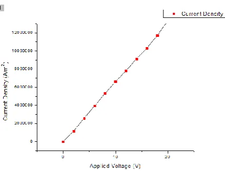
Figure 3 exhibits the snapshot of the maximum current density of the device for an applied voltage of 24V. This shows that, the current flow is maximum in the narrow arm and moderately less in wide arm. The maximum current density of the structure for 24V is
9.9725 x 10⁷ A/m2. For the voltage range of 0-24V, maximum current density of the device is marked against the applied voltage as demonstrated in the Figure 4. Current density increases linearly with the applied voltage.
Figure 3 Current Density Distribution of the device for an applied voltage of 24V
Figure4 Current Density Vs Applied Voltage
3.2 Temperature
113
Copyright © 2017. Vandana Publications. All Rights Reserved.
Figure 5 Temperature across the device for an appliedvoltage of 24V
Figure 6 Applied Voltage Vs Temperature
3.3 Stress and Displacement
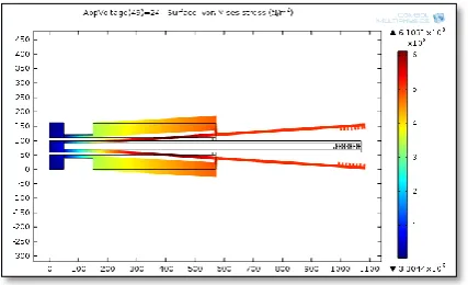
The stress distribution on the device for an applied voltage of 24V is illustrated in Figure 7. The stress is low and uniform in the most parts of the device and the maximum stress occurs at the flexure. As the applied voltage increases, the stress and the displacement of the arm increase. For the applied voltage of 24V, the maximum stress at the connectors is 60MPa, which is low compared with the yield stress of silicon.
Figure 7 Stress distribution of device for an applied voltage of 24V
Figure 8 exhibits the increase in the displacement of the upper arm measured with respect to its original position corresponding to the increase in
applied voltage. We observe that the device shows maximum displacement of 64μm at 24V. The profile is well matching with the parabolic fit.
Figure 8 Applied Voltage Vs Displacement
IV.
CONCLUSION
A novel model of electro-thermal based silicon microgripper is designed and simulated using COMSOL. The microgripper capable of producing a large displacement at a reasonably low applied voltage is presented. This design of microgripperis used for movement of optical components and for driving gears of motors. The design of a silicon microgripper has been analyzed, and the simulation results, using COMSOL MULTIPHYSICS software v4.3b was conferred. Simulation results show that the temperature shows up 1470 K (1327°C) at 24 V, and this temperature is less than the melting point of silicon. The experimental results show the fidelity of the devices at high temperatures. Hence, the design of silicon microgripper presented in this article has the advantage of low-power dissipation, and large displacement.
REFERENCES
114
Copyright © 2017. Vandana Publications. All Rights Reserved.
[5] K. Molhave et al.,“Towards pick-and-place assemblyof nanostructures,” J. Nanosci. Nanotech.4(3), 279–282 (2004)
[6] L. Sujatha, N.Vigneswaranb, S. Mohamed Yacinc, “Design and Analysis of Electrostatic Micro Tweezers with Optimized Hinges for Biological Applications Using CoventorWare”, international conference on design and manufacturing, IConDM 2013.
[7] N. La Lafitte et al., “Real-time sensing of molecule binding on DNA with silicon nanotweezers,” in 15th Int. Conf. Miniaturized Systems for Chemistry and Life Sciences, Seattle, Washington, The Printing House Inc., Stoughton, WI (2011).
[8] Nilesh D Mankame and G K Ananthasuresh, Comprehensive thermal modelling and characterization of an Electro-thermal compliant microactuator, J.Micromech.Microeng. Vol. 11 452– 462 (2001) [9] R. Voicu et al., “Design study for an electro-thermally actuator for micromanipulation,” Romania. J. Inf. Sci.Technol. 12(3), 402–409 (2009).
[10] Saravanan Mani, Selvakumar Varatharajan
Subramani, Siddhartha Goutham Murali,
SujathaL,“Performance of silicon-on-insulator multiuser MEMS processes-based electrothermally actuated
silicon microgrippers”, journal of
Micro/Nanolithography, MEMS, and MOEMS (2013). [11] X. Ye and Z. J. Zhang, “Piezoelectric-ceramic-based microgrippers in micromanipulation,” in Piezoelectric Ceramics, E. Suaste Gomez, Ed., pp. 253– 268, InTech, Shanghai, China (2010).
[12] Y Choi, J Ross, B Wester and M G Alle, “Mechanically driven microtweezers with integrated microelectrodes”,journal of micromechanics and microengineering, 25 April 2008.